In accordance with the “Rules for the technical operation of consumer electrical installations,” a single-line power supply diagram is one of the types of executive documentation that must be available to organizations and individuals operating electrical networks and equipment without fail. In this article by the editors of HomeMyHome.ru we will talk in detail about what such a scheme is, what it should include, as well as the rules for its design in accordance with all regulatory documents.
Single-line diagram of power supply for a country house
What is a single-line power supply diagram and why is it needed?
A single-line power supply diagram is a technical document that displays all elements of the facility’s electrical network, indicating their characteristics and parameters, as well as the installed and calculated power of the facility as a whole. The term “single-line” means that all electrical connections existing at the facility, regardless of their phase, are displayed on the diagram as one line. The rules for the design of single-line diagrams are regulated by GOST 2.702-2011 “Unified System of Design Documentation (ESKD). Rules for the execution of electrical circuits." The main purpose of such as-built documentation is to be informative and provide a visual perception of the configuration of the facility’s electrical network, which is necessary for making decisions during the operation of the energy sector.
An example of designing a single-line power supply diagram for an industrial enterprise
Types of single-line electrical diagrams
Depending on at what stage of the work on creating the electrical network of the facility a single-line diagram is drawn up, its type and direct purpose depend. At the stage of developing design documentation, a design single-line diagram is drawn up, which serves as the main document for calculating the parameters of the power supply system. It is this document that is necessary for subsequent approvals with the authorities issuing technical conditions for connecting the construction project to existing electrical networks, which are the electrical grid organizations at the location of the electrical energy consumer facility.
For your information! The procedure for obtaining technical conditions for connecting to electrical networks is regulated by a number of documents. Among them: Decree of the Government of the Russian Federation No. 861 of December 27, 2004 “On approval of the Rules for non-discriminatory access to services for the transmission of electrical energy and the provision of these,” “Rules for non-discriminatory access to the services of the administrator of the wholesale market trading system and the provision of these.” All regulatory documents must be taken into account when developing documentation.
Design diagram of an apartment panel of a country house
At the stage of operation of the facility, single-line executive diagrams are drawn up, which display all the changes made to the configuration of the electrical network during its use. This may be due to the modernization of the equipment used or its replacement, the addition of new capacities or changes in the configuration of trunk and group lines. At large facilities, where the power supply system is divided into several levels, single-line diagrams are drawn up for each group of consumers: “facility as a whole - workshop - section”, etc. Initially, a drawing is made showing the substations (SS) and the configuration of the networks connecting them, then a diagram of the TS or main switchboard (main distribution board) and then - each power or lighting panel available at the facility.
For your information! At facilities of various forms of ownership, the person responsible for the energy sector is responsible for maintaining technical documentation and its compliance with the requirements (PTEEP Chapter 1.2 “Responsibilities, responsibility of consumers for compliance with the rules”).
Executive diagram of a 2-transformer substation
Based on single-line diagrams, other electrical diagrams of the power supply system are developed: structural and functional, fundamental and installation.
Principles for designing a single-line power supply diagram
When developing and executing as-built documentation, it is necessary to comply with the requirements for similar documents reflected in the regulatory literature, as well as PTEEP and PUE (“Rules for the Construction of Electrical Installations”).
What should a single-line power supply diagram include?
Single-line power supply diagrams should reflect the following information, namely:
- the boundary of the area of responsibility of the organization supplying electrical energy and its consumer;
For your information! The boundary of the area of responsibility is displayed in the Electricity Supply Agreement for a specific facility.
Displaying the zone of balance sheet ownership on the power supply diagram of the facility
- input distribution devices (IDUs) or main switchboards, as well as transformer substations on the consumer’s balance sheet with display of ATS (automatic transfer switching) devices, if any;
Important! If there is an autonomous power source in the power supply system, it must be reflected on a single-line diagram.
- electrical energy metering devices indicating the transformation ratio of current transformers when using meters operating on a secondary current of 5 Amperes;
- information about all distribution cabinets available at the facility for both power equipment and lighting systems;
- lengths of main electrical lines, indicating the brand of cables, wires and methods of laying them;
- technical parameters and operating status of all automatic shutdown devices, which include circuit breakers, RCDs and fuses;
- data on all electrical loads connected to the equipment displayed on the diagram, indicating their power, current and cos ϕ.
Option for designing a single-line power supply diagram for an administrative building
Design stages
The presence of a single-line power supply diagram is a prerequisite for obtaining permission to connect the construction site to the networks of the power supply organization, therefore, before starting its development, it is necessary to request technical conditions.
In this regard, all work on designing a power supply circuit can be divided into several stages:
- Request and receipt of technical specifications;
- Development of a single-line power supply diagram based on the received documents;
- Coordination of the developed documentation with the organization that issued the technical specifications.
Option for registration of technical specifications for power supply
Design rules, GOST requirements
When designing a single-line power supply diagram, it is necessary to comply with the requirements of GOSTs regulating this process, namely:
- GOST 2.709-89 “Unified system of design documentation (ESKD). Conventional designations of wires and contact connections of electrical elements, equipment and sections of circuits in electrical circuits";
- GOST 2.755-87 “Unified system of design documentation (ESKD). Conventional graphic symbols in electrical diagrams. Switching and contact connection devices";
- GOST 2.721-74 “Unified system of design documentation (ESKD). Conditional graphic designations in schemes. Designations for general use (with Amendments No. 1, 2, 3, 4)";
- GOST 2.710-81 “Unified system of design documentation (ESKD). Alphanumeric designations in electrical circuits (with Change No. 1).”
An option for designing a single-line power supply diagram in accordance with these GOSTs is shown in the following figure.
Calculated single-line diagram of power supply for a residential building
Conventions used in drawing up single-line diagrams
All elements of the power supply system are displayed on the diagram in the form of graphic images, which are regulated by the regulatory literature specified in the previous section of the article. Electrical boxes and cabinets for various purposes are shown as follows.
Electrical installation products (sockets and switches), depending on the design and type of execution, are displayed like this
Electric lighting devices are depicted as follows
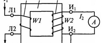
Power transformers and current transformers are depicted as follows
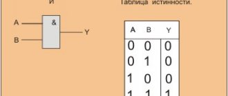
Electrical measuring instruments look like this on power supply diagrams, in accordance with GOST The intersection of electrical lines and the connection points of electrical wiring, as well as grounding look like this Switching devices (circuit breakers and starters, short circuiters and separators, as well as other devices) are shown like this
In order to find out how to correctly draw up as-built documentation, you need to study all the requirements of GOSTs or use a special computer program that will take into account all these requirements automatically when using it
Methods of transmitting electricity
There are two ways to transfer electricity:
- Direct transmission method.
- Converting electricity into another form of energy.
In the first case, electricity is transmitted through conductors, which are a wire or a conductive medium. This transmission method is used in overhead and cable power lines. Converting electricity into another form of energy opens up the prospect of wireless supply to consumers. This will eliminate the need for power lines and, accordingly, the costs associated with their installation and maintenance. Below are promising wireless technologies that are being improved.
Technologies for wireless transmission of electricity
Unfortunately, at the moment, the possibilities of transporting electricity wirelessly are very limited, so it is too early to talk about an effective alternative to the direct transmission method. Research work in this direction allows us to hope that a solution will be found in the near future.
Scheme of electricity transmission from power plant to consumer
The figure below shows typical circuits, of which the first two are open-loop, the rest are closed-loop. The difference between them is that open-loop configurations are not redundant, that is, they do not have backup lines that can be used when the electrical load increases critically.
Example of the most common power line configurations
Designations:
- Radial diagram, at one end of the line there is a power plant producing energy, at the other there is a consumer or distribution device.
- The main version of the radial circuit, the difference from the previous version is the presence of branches between the initial and final transmission points.
- Main circuit with power supply at both ends of the power line.
- Ring type configuration.
- Trunk with a backup line (double trunk).
- Complex configuration option. Similar schemes are used when connecting critical consumers.
Now let's look in more detail at the radial circuit for transmitting generated electricity via AC and DC power lines.
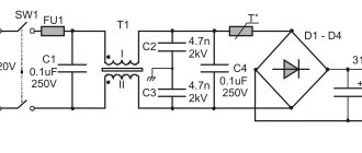
Rice. 6. Schemes for transmitting electricity to consumers when using power lines with alternating (A) and direct (V) current
Designations:
- A generator where electricity with a sinusoidal characteristic is generated.
- Substation with step-up three-phase transformer.
- A substation with a transformer that reduces the voltage of three-phase alternating current.
- An outlet for transmitting electrical energy to a distribution device.
- A rectifier, that is, a device that converts three-phase alternating current into direct current.
- The inverter unit, its task is to form a sinusoidal voltage from a constant voltage.
As can be seen from diagram (A), electricity is supplied from an energy source to a step-up transformer, then, using overhead power lines, electricity is transported over considerable distances. At the end point, the line is connected to a step-down transformer and from it goes to the distributor.
The method of transmitting electricity in the form of direct current (B in Fig. 6) differs from the previous scheme by the presence of two converter blocks (5 and 6).
Closing the topic of this section, for clarity, we present a simplified version of the city network diagram.
A clear example of a power supply block diagram
Designations:
- A power plant where electricity is produced.
- A substation that increases voltage to ensure high efficiency in transmitting electricity over long distances.
- High voltage power lines (35.0-750.0 kV).
- Substation with step-down functions (output 6.0-10.0 kV).
- Electricity distribution point.
- Power cable lines.
- The central substation at an industrial facility serves to reduce the voltage to 0.40 kV.
- Radial or trunk cable lines.
- Introductory panel in the workshop room.
- District distribution substation.
- Cable radial or trunk line.
- Substation that reduces voltage to 0.40 kV.
- Input panel of a residential building for connecting the internal electrical network.
Transmission of electricity over long distances
The main problem associated with this task is the increase in losses with increasing length of power lines. As mentioned above, to reduce energy costs for transmitting electricity, the current is reduced by increasing the voltage. Unfortunately, this solution gives rise to new problems, one of which is corona discharges.
From the point of view of economic feasibility, losses in overhead lines should not exceed 10%. Below is a table showing the maximum length of lines that meet the profitability conditions.
Table 1. Maximum length of power lines taking into account profitability (no more than 10% losses)
| Overhead voltage (kV) | Length (km) |
| 0,40 | 1,0 |
| 10,0 | 25,0 |
| 35,0 | 100,0 |
| 110,0 | 300,0 |
| 220,0 | 700,0 |
| 500,0 | 2300,0 |
| 1150,0* | 4500,0* |
* - at the moment, the ultra-high-voltage overhead line has been switched to operating at half the rated voltage (500.0 kV).
Programs for registration of as-built documentation
Currently, in order to design a developed single-line diagram in accordance with the requirements of GOST, it is enough just to have a personal computer and special software that allows you to do this work. There are several types of computer programs designed for these purposes:
- "Compass-Electric" – a free program, quite easy to use, popular among engineers and technical workers working in the services of the chief power engineer of enterprises of various profiles.
Drawing up an electrical circuit using Compass-Electric - Microsoft Visio is a free program that, as a rule, people use when drawing up a power supply diagram for a private house or apartment on a one-time basis.
- “1-2-3 scheme” is a free program that is popular among students and aspiring specialists in this field of technology.
- “Eagle” - the program is implemented in free and paid packages, differing in their technical capabilities.
- “DipTrace” is a program used for drawing electrical circuits and drawing printed circuit boards used in the manufacture of electronic devices.
- "AutoCAD Electrician" is one of the most famous and widespread programs used by both professional designers and ordinary users with sufficient experience in working with computer technology.
Work on drawing up a single-line diagram of a switchboard in the AutoCAD Electrician program
Analysis of electrical wiring diagrams
Let's look at several typical schemes that are used during construction or major repairs. All options are united by the presence of a protective group: dividing the electrical wiring into circuits, each of which is connected to a separate circuit breaker.
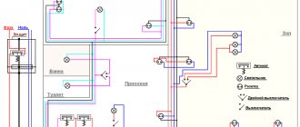
Option #1 – general plan for the whole house
This is not a wiring diagram, but a listing of all electrical devices that are planned to be located in the house. Using it, you can calculate how many automatic machines and RCDs you will need, and calculate the total number of power lines leading to the switchboard.
Here you should indicate the type of power supply network in order to select the correct cable. For a 3-phase network, use a 5-wire cable, for a 1-phase network, use a 3-wire cable.
The organization that supplies electricity to the house is responsible for some of the devices. This is an electric meter and input protection device, which is usually installed on the outer wall of the house or on a pole supplying the cable (+)
The electrical panel is located in a separate room inside the house, in the hallway, or in the nearby garage. Voltage stabilizers and a backup generator are also installed there, which supplies the house with electricity during periods when the centralized line is disconnected.
For ease of maintenance of a two- or three-story mansion, an electrical panel is also installed on each floor. All distribution boards are connected to an input cable - copper wire with a cross-section of 15-35 mm².
There is no need to skimp on protection devices: it is recommended to install an RCD on each socket circuit, circuit breakers on the light lines for each room, as well as for air conditioners, heating boilers, underfloor heating systems, etc.
If you plan to place several lamps and sockets in a separate room, then you need to mount a distribution box at the entrance. It connects the input cable to the lighting line and socket group.
Option #2 – sample wiring diagram
To draw a wiring diagram, you need to take a house plan and mark on it where electrical devices will be installed.
This document becomes the basis for drawing up an estimate - it is easy to use it to count not only the number of switches, sockets and additional materials, but also to calculate the footage of wires.
Wiring diagram of the electrical network of a one-story house. To make it easier to navigate the electrical lines leading from the electrical panel to the rooms, the contours are marked in different colors
The point of entry of the power line into the house and the installation location of the electrical panel must be indicated. Then, on separate lines, distribution boxes, electrical installations, and lighting fixtures should be noted.
High power devices also need to be labeled as they are powered by individual lines.
If outbuildings are connected to the building - a bathhouse, a garage, a workshop - this should also be reflected in the diagram, since it is part of the electrical wiring in a particular private house.
There are no special symbols for hand-drawn diagrams; the main thing is that the home owner and installers understand what lies behind each symbol. However, it is better to use generally accepted symbols for electrical circuits in order to later understand the project yourself.
Option #3 – technical solution for a small house
All plans and diagrams are similar, since they are built on the same principle, but they may differ in the number of installed sockets and lighting circuits, and, consequently, in the number of protective devices connected to them.
A sample diagram for a one-story house, inside of which there are 3 rooms, a corridor, a kitchen, and a bathroom. The power lines are assembled so that one of them connects the corridor and the room, the second - 2 rooms
An input switch is installed in front of the network, which, if necessary, can be used to de-energize the entire house and turn off the electricity meter. Then comes the counter, and after that comes the protective groups.
For powerful units, such as a heating boiler or a washing machine, 25-40 A machines are installed. The wire cross-section should also be increased to 3.5-5 mm².
Using such a diagram, it is not possible to calculate the footage of wires, but the number of sockets, distribution boxes, switches, RCDs, and automatic circuit breakers is easy to calculate.
Option #4 – electrical circuit for the basement/garage
Often, the basement of a private house becomes a utility room where a washing machine is installed and a dryer is equipped, a cellar for storing crops, or even a warm garage. It is much more convenient when such a room is fully equipped with sockets and lamps.
The diagram shows the wiring of the electrical network with an electricity meter. If the garage is located in the basement or in an extension, a separate meter is not needed
If you do not take into account the meter, the electrical panel will remain with input circuit breakers, a grounding bus, a 20 A RCD, three circuit breakers: on the lighting line, for sockets and for the compressor. Additional powerful equipment also requires automatic protection.
Option #5 – principles of kitchen wiring
The electrical circuit for a kitchen in a private house is practically no different from a similar circuit for a city apartment.
Its peculiarity is a large number of connected electrical appliances, therefore, it will be necessary to allocate several power lines with separate circuit breakers.
The main difficulty is placing the socket blocks so that they are close to the devices and at the same time freely accessible for possible repairs or switching of devices (+)
When drawing up a vertically oriented diagram, it is necessary to display on paper a furniture set with the arrangement of all equipment.
Socketless connections, for example, at an oven, are made under the countertop, near the wall, while sockets for a toaster, electric kettle, multicooker, and food processor are better placed above the work table.
Small household appliances are easier to unplug if the electrical installation device is at hand. Sockets installed near the sink must have a degree of protection of IP44 or higher.