Electrical network repair is work related to electricity. There is always a danger of injury to an employee by electric current of various voltages. How do you know if current is flowing through a wire or cable? A voltage indicator (VI) will help determine which wire is energized. Disabling the area under the potential difference does not mean that it is absent on the current-carrying parts. Only with the help of such devices can you be sure that it is not there.
Voltage indicator
Device and principle of operation
The main structural elements included in any indicator are:
- one or two metal tips, the tip of which directly touches the exposed live part to determine the presence or absence of voltage;
- light, sound or digital indicator that gives a signal in the presence of electricity;
- a housing made of insulating material that contains a neon light bulb, an LED or an LED matrix, and may also contain an electronic board and a quenching resistor.
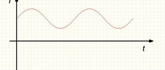
The operating principle and design of the indicators depend on what kind of current will flow: active or capacitive. The first type of UN involves working with both alternating and direct currents up to 1000 V. The second is designed to work only with alternating currents.
Attention! An incandescent lamp with leads attached to it to monitor the voltage on the wires is not an indicator. Its use is strictly prohibited.
Structurally, indicators can have two housings with tips connected to each other by a conductor. In this case, the length of such a conductor should not be more than 1 m; the places where it enters the housings (handles) are framed with thickening and have shock-absorbing inserts.
Double pole indicators
The principle of operation of indicators of this type is based on comparing the potentials in 2 current-carrying parts of the equipment being tested: zero and phase. Unlike single-pole indicators, these devices are equipped with two probes. A person does not come into contact with the controlled voltage and is separated from its influence by a layer of insulation. The indicator includes a signal lamp and 2 resistors: a shunt and a current-limiting one. The connection between the probes is made with a rubberized flexible wire.
You might be interested in: Formula for calculating the capacitance of a capacitor depending on the area of the plates
Of the old models of bipolar voltage indicators up to 1000 V, MIN 1 and UNN-10 with an operating potential range of 70–660 volts are still used. The signal lamp of these devices lights up at 60–65 V. Using the indicated products, the circuit is checked for integrity. Simple versions include indicators of the PIN-90, UN-500, UNNU-1 series - they only detect the presence of voltage. More advanced models ELIN-1, IPM also indicate the potential value and polarity.
LEDs of all colors, neon bulbs and digital indicators are used as a signal. There are also combined indicators - sound is added to the glow, which increases the safety of handling the device. The most famous digital two-pole voltage indicator is the multimeter. It is able to determine the magnitude of AC and DC potential, strength and frequency. The device is often used to solve everyday problems.
Types of indicators for determining voltage
The conductive parts of the installations with which electrical personnel have to work are divided according to the value of the supply voltage. A distinction is made between circuits with voltages up to 1000 V and over 1000 V. Due to the fact that the use of a voltage indicator involves touching a bare wire with its working electrode, indicators are divided into voltage indicators up to 1000 V and those designed for voltages above 1000 V.
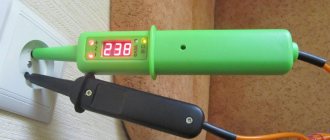
Checking the voltage at the outlet
In addition, UN are divided according to the following characteristics:
- number of poles (with one or two contact electrodes);
- type of current (direct or alternating);
- type of indicator (neon, LED, digital, acoustic).
In the line of modern indicators, there are samples with non-contact testing for the presence of high voltage. UN makes it possible to check the presence of Uphase (Uph) on high-voltage lines (HVL) and current bus assemblies of closed (closed switchgear) and open (ORU) switchgears with Uph from 1 kV and higher.
Information. A non-contact UN produces an intermittent optical or acoustic signal when its testing part approaches an element located under Uph. Its own power supply allows not only to issue indication signals, but also to monitor the serviceability of the UN.
Single pole pointer
Low voltage indicators (LVL) with one pole have a neon light bulb located in the housing. It has an ignition threshold of up to 90 V and a series-connected resistance, one end of which is connected to the contact pad on the indicator body. To determine the presence of Uph, you need to touch the bare wire with the tip of the pointer, and with your finger - the contact pad on the body. As a result, the capacitive circuit is closed through the human body to the ground. When there is voltage, the indicator lights up.
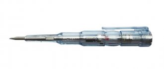
Single-pole indicators can be made in the form of a screwdriver with a transparent body, inside of which a light bulb glows. Examples of such probes are INO-70, UNN-90 and others.
Carefully. Single-pole indicators are designed to test the absence or presence of AC voltage only. Before use, it is necessary to know the value of the maximum permissible potential difference. This information is printed on the device body.
Single-pole indicator in the form of a screwdriver Vira 100-500V 390220
Two-pole voltage indicator
Pin 90 voltage indicators refer to voltage indicators that have two poles connected to a section that conducts electric current. Pin 90, as a model representing such testers, allows you to work in the range of values from 50 V to 1000 V. They can determine the presence of a “phase” by the glow of the lamp, touching one electrode to the test area, the other to the neutral or grounding conductor. In the absence of such, the presence of phase voltage can be determined by touching one contact tip to the “phase”, and the other by touching with a finger. In three-phase AC networks, you can check both phase (220 V) and line voltage (380 V).
Important! Before working with the UN, it is necessary to visually inspect the housings for the absence of mechanical damage, and the flexible conductor for the integrity of the insulation. Before work, you need to make sure that the indicator is working properly by touching an area that is known to be energized.
Double-pole indicator Pin 90M
High voltage indicators (HVN) over 1 kV
On 6-10 kV power lines, a voltage indicator UVN 10 is used. This device allows you to monitor Uph, both on overhead lines and in ground-based high-voltage installations. It belongs to the group of basic protective equipment for working in power plants, since with its help you have to touch live parts of installations.
The device includes: a working part, an insulating section and a handle. In the working part there is an electrical circuit that converts the electrical signal into light and sound form. The circuit is located in the area of the shader (reflector), which is designed to enhance optical and acoustic indications. This is achieved through its directed action.
Basic requirements for the design of UVN:
- indication signals must have a continuous or intermittent operating mode and be clearly recognizable;
- the insulating part must be located strictly between the handle and the working part;
- if the insulating part consists of several links (collapsible) or telescopic, then the fastening between the links should ensure the strength of the entire structure, sliding fixation against spontaneous movement;
- the pointer must have a mass that allows one person to operate it;
- The rubber or plastic cover of the shade must contain a mirror reflector.
Such indicators must have a design that allows testing the voltage on a 6 kV or 10 kV overhead line without grounding their working parts.
UVN-10 appearance
Universal pointers
The instruction diagram of such devices describes them as a portable tester that allows for sound and light indication during testing. It is used to determine:
- phase;
- zero;
- absence or presence of voltage (from 12 to 500 V DC and up to 380 V AC).
With the help of such UN, you can perform a “continuity test” of the circuit integrity and find out the order of alternation or coincidence of phases. The power source in the universal probe is a capacitor with a large capacitance value. It can be equipped with a line of LEDs or a liquid crystal display.
One of the representatives of universal UN models is “contact 55 em”. It has the following parameters:
- operating voltage range – 24-380 V DC or AC;
- electrical insulation strength – 1 kV;
- current through the pointer at 380 V – up to 10 mA;
- Rmax of the external circuit during continuity is not less than 500 kOhm.
Such a device can operate without recharging for 24 hours, charging time is no more than 30 seconds.
Universal UN Contact 55 EM external device
The presence or absence of voltage is monitored by light and sound indication. The ability to mount a second probe on the body of the first allows you to easily test the power outage at the outlet.
Contact 55EM in action
General information about indicators
Potential detection devices on current-carrying network elements operate on various principles related to the properties of electricity. Low voltage indicators are manufactured in accordance with the action of a certain quality indicator. There are standards that define the requirements for control devices.
Operating principle
Inside every object there are electrical charges: cations, anions, electrons. Their number determines the magnitude of the positive or negative potential. The difference in the values of this indicator is the voltage, the formation of which in a closed circuit causes the movement of charges - electric current. This property is used when creating devices for detecting potential:
- a resistance is installed in the path of the particles, reducing their concentration to a minimum safe for humans;
- the remainder of the electricity is converted into magnetic, light, sound energy;
- Based on the intensity of the received signal, one judges the presence or absence of potential on the conductor.
A contact or two terminals of the device are connected to the network elements and the presence or absence of current is verified. The available voltage will be indicated by the sound of the built-in microspeaker, an LED light or the arrow of a measuring device.
Product classification
Knowledge of the range of industrially produced devices will help you select the most suitable low voltage indicator for your conditions. The division of modifications occurs according to different criteria. Manufacturers offer designs in the following categories:
- Depending on the type of current being measured - for operation in DC or AC voltage circuits.
- According to the number of operational contacts - single- and double-pole. The latter are universal; they are used to determine the potential in any circuit. The principle of their operation is based on the passage of active electrons. The first type of indicators has a different device - single-pole ones: they use the properties of capacitive current, and use devices only in alternating networks.
- In connection with live parts - contact and non-contact, allowing you to detect voltage indirectly without touching the network element. An example of the latter type of devices are Chinese-made indicators: MS-8 and 58. They consist of an LED, radio components and are powered by miniature batteries, the non-contact measurement range is 70–600 V, polarity detection is 1.5–36 V. For inexperienced craftsmen, such an indicator It’s better not to use it: it reacts to all surrounding objects.
- Depending on the type of indicator - digital and LED.
There are differences in devices in terms of measurement range and appearance. The voltage allowed for operation is marked on the device body. Using a 220 Volt indicator on a 0.4 kV network is dangerous to life.
Manufacturing requirements
Voltage indicators up to 1000 V are subject to certain conditions that are mandatory for device manufacturers. The full list of requirements is set out in the state standard. The most important conditions are the following:
- light and sound signals are clearly recognized, the interval between pulses lasts no more than a second, the load on the indicator is up to 50 V;
- the single-pole pointer is enclosed in 1 housing, on which there is an electrode tip, and on the handle there is a contact for the operator’s finger;
- Bipolar devices have 2 separate shells connected by a meter-long wire and each equipped with a working electrode with an open tip of up to 7 mm.
This will be interesting to you The design and use of a resistor in an electrical circuit
Voltage indicators can combine other functions - searching for a phase conductor, checking the integrity of the network, establishing polarity. The condition for expanding the capabilities of the device is maintaining the safety of use for its main purpose. Before starting work, the indicator is checked with a potential of 2 kV, turned on for a minute.
In some cases, preference is given to bipolar voltage indicators, and the safest is considered to be non-contact - it reads information through a magnetic field. When checking for potential, the connection between the pointer and the current-carrying element is maintained for at least 5 seconds.
Design and method of application
The product instructions describe the design features and operating rules. Standard recommendations may have some discrepancy with individual developments. However, the basic requirements are met for all models:
- ferrule;
- dielectric housing;
- display device.
Voltage tester
When working, it is necessary to touch the area under test, taking into account what voltage may be there and whether it falls within the operating range of the indicator.
Important! If there is no assumption at what voltage the de-energized section may be under, the lack of potential is checked first by the UVN, then by the UNN.
High voltage device (more than 1 kV)
Such devices can be either single-pole or double-pole: UVN - 10, UVN - 80 and similar models. For example, you can consider a high voltage indicator UVN 10.
With its help, the phasing of power transformers in power plants and cables designed to operate on alternating current with a frequency of f = 50 - 60 Hz and U = 6 - 10 kV is carried out.
There are several versions of this device, which have:
- pulse light indication with self-control (UVNU -10 SZ);
- the same parameters plus a power source (UVNU - 10 SZ IP);
- phase indicator, light-pulse indication plus phasing tube, no IP (UVNU - 30 SZ TF);
- the same parameters as the previous model, plus IP (UVNU - 10 SZ IP TF);
- UN with IP contact-non-contact (UVNU – 10 SZ IP KB);
- phase indication, power supply, phasing tube, two-pole (UVNU – 10 SZ IP KB TF).
Despite the abundance of indicators designed for different voltages and types of current, they all must undergo periodic testing in special laboratories.
Pointer tests
Laboratory tests are carried out by organizations that have a special license for this. To carry out the test, a circuit is assembled, which includes a high or low voltage indicator.
The UNN is tested for the insulation condition and the indication voltage value. They also check its operation at increased voltage, while measuring the current. The voltage, gradually increased from zero, is brought to exceed the operating voltage by 10% and is maintained for 1 minute.
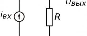
Electrical installation diagram for testing the insulation of the housing and wires of the ULV up to 1000 V
The UVN is tested starting from the working part, applying voltage to the tip and screw connection. If the indicator voltage is higher than 35 kV, the working part is not checked, only the condition of the insulating part and the handle is tested.
Scheme of the testing facility for UVN
The results obtained are documented in a protocol and entered into a journal. A product approved for use is equipped with a tag with a stamp indicating the date of the next verification.
Voltage gauges and indicators are used to ensure the safety of operating personnel during work; they can also be fraught with danger. Storage, correct use and daily visual inspection must be ensured by those directly using the indicator. It is prohibited to use the device if the inspection period has expired, or if it has been subjected to mechanical damage as a result of a fall or impact.
Reading time for the article is approximately 2 minutes. Portable voltage indicator PIN-90. Passport 3 PE 344.013 PS
1. PURPOSE Voltage indicator PIN-90 is designed to check the presence or absence of voltage between non-insulated live parts, as well as between them and grounded parts in electrical installations of alternating and direct current at a rated voltage of 65 to 750 V in mine conditions hazardous due to gas or dust . Climatic operating conditions of use: Air temperature, °C -50+45 Relative humidity, % 100 (+ 35 °C) The indicator can also be used in explosion-proof media. Atmospheric pressure, kPa 60—106
TECHNICAL CHARACTERISTICS Indication voltage range: direct current, V 75–750 Temporary current with a frequency of 50 Hz V 65–750 Lamp ignition voltage at a frequency of 50 Hz V, no more than 60
Insulation strength test voltage kV 3 Maximum current passing through the indicator, mA, no more than 1.0
Operating mode – repeated short-term Duration of current flow, s. no more than 10 C. Overall dimensions, mm Ф25Х156 Weight, kg. no more than 0.3
3. DELIVERY SET Voltage indicator PIN-90 — 1 pc. Passport - 1 copy. Case - 1 pc.
4. DEVICE AND PRINCIPLE OF OPERATION The portable voltage indicator consists of the following parts: - the main body, consisting of a plastic handle with an outer metal tip (part of the elements of the electrical system 9 are mounted inside the body: - an auxiliary body, consisting of - a plastic handle with an outer metal tip, a limiting resistance is built into the housing, filled with a compound: - a connecting wire 800 mm long. The operating principle of the indicator is based on the glow of the lamp when active current flows. The indicator housing is made of moisture-resistant plastic and is protected from external influences of dust and moisture penetration.
5. INDICATION OF SAFETY MEASURES AND MAINTENANCE During operation, the indicator must be held on plastic housings so that the operator’s fingers do not protrude beyond the limiting stops on them and do not allow one tip to touch two live parts that are at different potentials.
Before commissioning and during operation, the voltage indicator must be tested within the time limits and according to the standards provided for by the “Rules for the use and testing of protective equipment used in electrical installations”, as well as the “Rules for the manufacture of explosion-proof and mining electrical equipment when used in explosive environments.
6. PREPARATION OF THE INDICATOR FOR OPERATION AND OPERATING PROCEDURE Before using the indicator, carry out a visual inspection of it.
If external damage to the housing or damage to the insulation of the connecting wire is detected, use of the indicator is prohibited.
When two tips simultaneously touch two electrical circuits that are under different potentials, the neon lamp should glow.
7. ACCEPTANCE CERTIFICATE The portable voltage indicator PIN-90 complies with TU25-0432,030-84 and is recognized as suitable for use.
Date of issue_____________. Quality Control Controller __________.
8. MANUFACTURER'S WARRANTY The manufacturer guarantees that the indicator meets the requirements of the specifications or the consumer's compliance with the conditions of operation, storage, and transportation. The warranty period is 24 months from the date the indicator was put into operation.
9. INFORMATION ABOUT COMPLAINTS
Date of inspection. Where and how checked. Result. Signature.
10. PACKAGING AND STORAGE INFORMATION
Packaging of indicators, marking of packaging containers and documentation placed in a box comply with GOST 9181-74.
Indicators are stored in warehouses on racks and cases at ambient temperatures from + 1 °C to + 40 °C and relative humidity up to 80% at a temperature of + 25 °C.
,185