Distinctive features of the operation of power systems are:
- Rapidity;
- Interconnectedness;
- Coordination of procedures for the production, distribution and consumption of electrical energy.
To control all processes in the power system, special automatic control tools are used. All used automation devices, according to their purpose and scope of application, are divided into two classes:
- Local and system technological automation;
- Local and system emergency automation.
The purpose of system technological automation is to ensure the normal operation of the equipment, namely:
- Starting turbine-generator units and putting synchronous generators into operation;
- Automatic regulation of voltage and reactive power on power plant buses;
- Automatic frequency regulation and ensuring the power plant’s given load mode;
- Optimal distribution of electrical load between blocks;
- Voltage regulation in the distribution network;
- Regulation of frequency and power flow.
System emergency automation is designed to prevent and most effectively eliminate the consequences of accidents, namely:
- Protection of electrical equipment from short circuits and non-standard operating methods;
- Automatic switching on after the fault has been eliminated;
- Independent activation of backup equipment;
- Automatic frequency unloading;
- Automatic elimination of asynchronous mode;
- Self-preventing stability failures.
The main role among emergency equipment devices is played by relay protection, which evaluates the behavior of the electrical supply system and its components in modes of large negative influences and sharp jumps in electrical characteristics.
Negative reactions can be caused by a number of factors, namely:
- Breakdown or short circuit of insulating elements of power lines due to lightning influences or when they are contaminated;
- Breakage of wires or lightning protection grounding due to ice freezing or large fluctuations;
- Mechanical deformation of supports, damage to insulators, jamming of wires;
- Incompetent actions of operational personnel;
- Factory defective equipment.
The main objectives of relay protection are:
- Independent detection of a faulty element and its subsequent isolation. The protective system provides a signal to trip the switches of this component, creating acceptable operating conditions for the untouched part of the energy system;
- Independently detect unusual operating conditions and use measures to correct them. Deviation from the usual mode is primarily caused by various overloads, the shutdown of which is not necessary. Having unloaded the equipment, the protection communicates this error signal to the operating personnel.
Lzsh: operating principle, application for relay protection and circuits
Logical bus protection is currently included in almost any microprocessor relay protection terminal. Its task is to turn off a short circuit on the switchgear buses in the minimum possible time, limited only by the own response time of the electronic part of the terminal. Typically this is from 0.1 to 0.15 s.
Why is LZSh the most effective protection for this part of the reactor plant? Let's consider possible options for eliminating short circuits on tires.
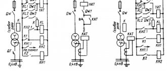
The first option is to use differential protection. To implement it, additional windings of current transformers will be required at all connections of the section.
They need to be connected to a differential relay, the task of which is to add up the currents entering the buses from the power feeders and the currents at the outgoing connections at the moment of a short circuit.
If the unbalance current exceeds the set value, the relay gives a shutdown command.
The system turns out to be very complex, but with complexity its reliability decreases.
In addition, current transformers with additional windings are more expensive. Restrictions are imposed on testing relay protection and automation connections: if a test current is accidentally supplied to it, the protection will operate falsely.
The option of using incomplete differential bus protection is also not very effective.
It differs from the previous one in that current transformers are used only for supply lines and powerful consumers. But its use, among other things, is very limited.
The next opportunity to protect buses is overcurrent protection of supply lines. In principle, this is done in the vast majority of cases. But this type of protection has a significant drawback. To detune the MTZ from short circuits at outgoing connections, its time delay must be greater than that of the MTZ of consumers. In practice this is 1 – 3 seconds.
As the short-circuit current increases, every second of its action becomes fatal for electrical equipment. The longer the arc burns, the more destruction it causes.
Behavior of LZSh during external short circuit
In the event of an external short circuit, the overcurrent protection of the connection at which it occurred is triggered. Naturally, the shutdown will occur after the time delay specified for the given fault current has expired. The blocking signal will be sent to the terminals of the feeders supplying the section.
LZSH will launch on these terminals. The appearance of a blocking signal will cause the LZSh at the supply line terminals to stop and shutdown will not occur.
In case of failure of the overcurrent protection of the outgoing line, the short circuit will be eliminated by the overcurrent protection of the supply feeder or breaker failure. LZSH is not responsible for refusal.
What does LZSH consist of?
Bus logic protection elements are not concentrated in one place. This is a system that combines protection terminals for supply and outgoing lines.
Outgoing lines, when launching their own protections (usually MTZ), generate a blocking signal LZSh. For this purpose, one discrete output is allocated to each of them. Signals from all outgoing lines of the section are sent to the discrete inputs of the power feeder terminals. For transmission, a power and control bus system is used, which is part of any modern switchgear. This is where the entire constructive part ends. All that remains is to set the correct LZH settings on all terminals and set the assignment of discrete inputs and outputs.
The terminals of the section switches receive the LZSh blocking signal from the connections of both sections that they connect. For this purpose, different digital inputs are used.
LZSH organization schemes
Behavior of LZSh during external short circuit
In the event of an external short circuit, the overcurrent protection of the connection at which it occurred is triggered. Naturally, the shutdown will occur after the time delay specified for the given fault current has expired.
But, if there is a LZH, the terminal will perform one more task: it will issue a signal to block it.
It will arrive at the terminals of the feeders feeding the section.
On these terminals, if the MTZ is triggered, the LZSh will start. It is in them that it is configured to turn off; on outgoing elements it is not needed, their task is only to transmit a signal that the short circuit is in their coverage area, and they are ready to eliminate it.
The appearance of a blocking signal will cause the LZSh at the supply line terminals to stop and shutdown will not occur.
In case of failure of the overcurrent protection of the outgoing line, the short circuit will be eliminated by the overcurrent protection of the supply feeder or breaker failure. LZSH is not responsible for refusal.
Operation of LZSh during short circuit on tires
If a short circuit occurs on the switchgear buses, no blocking signal will be received from the outgoing lines, since the short circuit current does not pass through them.
The launch of the overcurrent protection of the supply bus lines in the absence of a blocking signal will lead to an instantaneous action of the LZSh to disconnect the connections.
Moreover, all switches through which power is currently supplied will turn off independently of each other. If, in addition to the input, a sectional switch is turned on, then the LZSh will work on it as well.
The protection is called logical precisely because its work is associated with the analysis of the location of the short circuit in the system: if not a single terminal of the outgoing line sees the short circuit, then it is on the buses.
The area covered by the protection is limited to the installation sites of current transformers of all connections of the section. In this way, it is similar to differential bus protection, implemented in a classical way. When the LZSh is triggered, an ATS prohibition signal is generated for the damaged section.
Reliability of LZSh
Unlike other protections, LZSh rarely trips when checking relay protection and automation equipment by electrical laboratory personnel.
When working on outgoing connections, the blocking signal, although it arrives at the inputs of the power line terminals, does no harm.
Reliability of LZSh
LZSh, from the point of view of performance testing, differs from other types of protection. It rarely works when tested by employees of measurement laboratories. This is explained by the fact that the LPS is assigned a less significant role; accordingly, it has a longer response time and simply does not have time to get ahead of other types of protection.
Most often, logical bus protection fails due to a short circuit of the current transformer or its turn short circuit. Fortunately, this happens quite rarely. In this case, the transformer is simply not able to correctly measure the current flowing through the bus it controls. Therefore, the LZSh protection blocking signal cannot be generated, which leads to its unintentional activation.
Important! Before disconnecting the wires from the current transformer, its terminals must be shorted together. Otherwise, a high-voltage potential may be induced in the CT winding, which is dangerous to the life of operating personnel and can lead to equipment damage.
LPS is a relatively simple and effective system for ensuring uninterrupted operation of the power system. Its use significantly reduces the negative consequences of emergency situations, and also significantly reduces the risk of their occurrence.
What is relay protection and why is it needed?
You are here: In accordance with the requirements of the rules of technical operation of electrical installations (abbreviated PTE), power equipment of electrical networks, substations and power plants themselves must be protected from short-circuit currents and failures of normal operation. Special devices are used as protective equipment, the main element of which is a relay.
Actually, that’s why they are called that – relay protection and electrical automation devices (RPA). Today, there are many devices that can quickly prevent an accident in the serviced section of the power grid or, in extreme cases, warn personnel about a violation of the operating mode.
In this article we will look at the purpose of relay protection, as well as its types and design.
What is it for?
First of all, we’ll tell you why you need to use relay protection. The fact is that there is such a danger as the occurrence of a short-circuit current in the circuit. As a result of a short circuit, conductive parts, insulators and the equipment itself are very quickly destroyed, which entails not only the occurrence of an accident, but also an industrial accident.
In addition to a short circuit, overvoltage, current leakage, gas release due to decomposition of oil inside the transformer, etc. may occur.
In order to promptly detect danger and prevent it, special relays are used that signal (if equipment failure does not pose a threat) or instantly turn off the power in the faulty area. This is the main purpose of relay protection and automation.
Basic requirements for protective devices
So, in relation to relay protection and automation the following requirements are imposed:
In simple words, the purpose of relay protection and the requirements for it are that the devices must monitor the operation of electrical equipment, respond in a timely manner to changes in the operating mode, instantly disconnect the damaged section of the network and alert personnel about an accident.
Relay classification
When considering this topic, one cannot help but dwell on the types of relay protection. Relay classification is presented as follows:
As for the types of relay protection systems themselves, there are many of them. Let’s immediately look at what types of relays there are and what they are used for.
Separately, I would also like to consider the types of electrical automation, the purpose of which, unlike relay protection, is, on the contrary, to turn the power back on. So, in modern relay and automation systems they use the following type of automation:
In addition, there are the following types of automation:
So we looked at the purpose and areas of application of relay protection. The last thing I would like to talk about is what the relay protection consists of.
Relay protection and automation design
The relay protection device is a circuit consisting of the following parts:
Finally, we recommend that you watch a useful video on the topic:
Relay protection and automation in the energy sector for beginners
That's all we wanted to tell you about the purpose of relay protection and the requirements for it. We hope you now know what relay protection and automation is, what its scope is and what it consists of.
It will be useful to read:
Relay protection and automation in the energy sector for beginners
Other related articles
What types of time relays are there?
Operating principle of differential protection
The action of this protection is based on comparing the currents that enter and exit the area in need of protection. For such a comparison of current values, current transformers are used, since only through them is it possible to measure large current values. This is best seen in the simplest diagram below.
In the diagram, the current transformers are designated TA1 and TA2. Their secondary circuits are connected to the KA current relay. Thus, it turns out that the winding of the main protection relay receives the difference in current values from the two transformers, and during normal operating processes it will be equal to zero, which means the KA relay will remain unplugged. However, if an interphase short circuit (short circuit) occurs in the circuit that is being protected, then the relay winding will receive a value equal to the sum of several currents, this will set in motion the moving part of the electromechanical relay, which, in turn, will close the contacts and will give a signal to disconnect the equipment from the source of electrical energy. However, this is all in theory, but in practice a certain small unbalance current will always flow through the relay coil, which must be taken into account when calculating the coil.
Here are several reasons for this negative phenomenon:
- CTs (current transformers) can have characteristics that differ significantly from each other. To reduce these indicators, more precise transformers are used, manufactured in pairs specifically for this type of protection;
- Due to the magnetizing current arising in the winding of the protected transformer at the moment it is turned on from the idle mode to the operating mode with a load present. In order to avoid false operation of the KA relay, it is necessary to select a relay operation current greater than the highest value of the magnetizing current that the protected object, in this case a transformer, can produce;
- Due to different connections of windings (star-delta and vice versa). To do this, you need to select the number of turns of current transformers involved in differential protection in such a way that they compensate for these unfavorable values.
The unbalance current in differential protection that occurs during operation is a negative phenomenon that must be combated and which must be taken into account when calculating this protective electrical equipment.
Logical bus protection (LBP)
Today, logical busbar protection is an integral part of the relay protection and automation system for 6-35 kV switchgears.
Its spread was facilitated by the transition from electromechanical element base to microprocessor relay protection units. Just 15-20 years ago you would hardly have seen LZH in a project. The standard response time of a 6-10 kV overcurrent input is 1-2 seconds, versus 0.1-0.15 seconds for LZSh. The speed gain is obvious.
LZSh should be used with caution at substations with large 6-10 kV motors, which can feed an external short circuit with a current level sufficient to start the protection of connections and switchgear inputs. This can lead to false operation of the LPS with non-selective shutdown of the 6-10 kV section or blocking of the LPS in the event of a false start of connection protections.
Recently, in order to reduce the cost of projects, LZSh began to be used in ring networks with multilateral power supply (6-35 kV buses of substations, distribution centers, gas turbine power plants, etc.). For this purpose, the triggering elements of the protections are directed. This option must be comprehensively considered taking into account the reliability of the relay protection system and, in the case of particularly critical objects, preference should be given to differential busbar protection!
LZSH structure
LZS is distributed protection. It is not located in one specific terminal, but is distributed among the protections of inputs, CBs and outgoing connections (lines, transformers, motors, BSK, etc.).
Since the protection of 6-35 kV busbars is carried out by input and sectional switches, it is in the input and CB terminals that a breaking current stage (LCS) is implemented, operating with a minimum time delay (0.1-0.15 s).
The starting protection elements of downstream connections provide information about whether there is a short circuit at the connection, and if so, they close the output contacts of their terminal to transmit a signal to the input and CB terminals. This output signal is called “LZSh Block”.
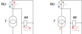
Short circuit at the connection (outside the LZSh coverage area)
It is worth noting that despite the name, LZSh protects not only the buses themselves, but also the switch area. As with differential busbar protection, its coverage area is determined by the installation locations of current transformers.
That's all about the Basics of LZSH! Next time we’ll talk about possible schemes for implementing logical bus protection in real projects.
Selection of LZSh operation settings
Logical bus protection is designed to quickly disconnect substation bus sections when short circuit currents flow through them.
The operation of the LZSh is based on the logic of blocking upstream switches. In our case, we use the following blocking logic:
1. R&A of outgoing lines from the bus section block their input and sectional switch.
2. The section switch blocks the operation of both inputs.
With this approach to the blocking logic, the LZSh settings at the inputs and sectional switch are set to the same in both current and time.
The sensitivity coefficient of the LZSh in relation to the minimum short circuit current at a 6 kV SS should be 2.
Operating current of LZSh Input = 1350 A
LZSh settings for 35/6 kV substation:
Operating current LZSh SMV = 1400 A
Actuation current of LZSh Input No. 1 = 1400 A
Actuation current of LZSh Input No. 2 = 1400 A
The LZSh response time is assumed to be 0.1 s in order to ensure the passage of blocking signals.
8. CALCULATION OF EMERGENCY AUTOMATION SETTINGS
Calculation of response parameters of automatic reclosure starting and control elements
Let's calculate double automatic reclosure on feeder No. 6.
According to the PUE clause 3.3.6, on lines with one-sided supply, it is possible to use 2-fold automatic reclosure if the technological process allows it.
Since only transformer substations are powered from the overhead line of our substation, the use of double automatic reclosure is permissible.
Let's calculate the response time of the first cycle:
Deionization time for 6 kV networks t
d = 0.1 s, the switch readiness time and the switch on time for microprocessor protection
SIPROTEC 4
are respectively equal to
t
gv = 0.3 s and
t
vv = 0.05 s, the drive readiness time
t
gp = 0.15 s.
Let us take the reserve time to be equal to
trep=0.75 s.
We calculate the AR time settings using formulas (26), (27), (28): s;
With; With. We select the largest of the settings, i.e. t
1 AR=1 s.
We will accelerate the protection after automatic reclosure, so that in the event of an unresolved short circuit, we do not create an even more unfavorable situation in the system, as well as to reduce the influence of the established short circuit current on the equipment. According to recommendations from the literature, we take t
ac=0.1 s.
We will select the response time of the second cycle according to the recommendations of the PUE:
With.
Automatic reclosing of 6 kV bushings will be performed in a single-shot version in accordance with PUE clause 3.3.2 and clause 3.3.6.
The calculation of automatic reclosure for other feeders is carried out similarly; the results are summarized in Appendix 7.
Calculation of response parameters of ATS triggering elements
Let's calculate the ATS for a sectional switch on cell 12.
Bus logic protection circuits
In this article we will talk about schemes for implementing logical busbar protection (hereinafter referred to as LPS) in 6(10) kV switchgear at direct operating current. The LZSh circuit can be constructed according to the scheme of parallel and serial connection of contacts of outgoing lines.
Let's consider a logical bus protection circuit with a series connection of contacts (Fig. 2). The block diagram of the 6(10) kV switchgear is shown in Fig. 1.
Fig. 2 – LZSh circuits according to the serial connection diagram
The principle of operation of the LZSh in a serial connection circuit is quite simple. If a short circuit occurs on the outgoing lines, their MTZ is triggered, thereby blocking the operation of the LZSh. In the event of a short circuit on the busbars, the MTZ of the outgoing lines do not start, the contacts are closed and the LZSH starts to operate. At this time, the input (sectional) switch is turned off with a minimum time delay.
This scheme has a number of disadvantages, namely: • with a large number of series-connected contacts, the reliability of the LZSh operation decreases; if one of the wires breaks, the LZSh fails. • it becomes more difficult to take out the outgoing line for repair; you have to put a jumper together where the LZSh contact is used, in order to avoid breaking the LZSh circuit.
Let us now consider the logical bus protection circuit with parallel connection of contacts (Fig. 3).
Fig. 3 – LZSh circuits according to a parallel connection diagram
This circuit is more reliable and has no disadvantages when connected in series. The principle of its operation is the same as with a serial connection.
The need for arc protection is caused by the imperfection of current
Despite the requirements of paragraphs of the PUE clause 3.3.31, clause 3.3.42 on the use of automatic reclosure of busbars and automatic transfer switches after the elimination of short circuits inside the switchgear compartments, today design organizations and operating enterprises reasonably doubt the need to fulfill these requirements and prefer blocking the automatic reclosure of busbars and automatic transfer switches during when the switchgear arc protection is triggered. This decision is justified by the negative experience of operating organizations in using automatic reclosure of medium-voltage busbars. Is this approach justified? Do existing protection solutions ensure that arc faults are disconnected within a time period during which no critical damage occurs inside the switchgear? Current step protections cannot be used as high-speed protection against arc faults due to the large time delays at the supply connections (usually more than 0.5 s). In order to reduce the operating time of current protection at supply connections, logical bus protection (LBP) is used, the operating principle of which is based on the transmission of blocking signals from protection devices for outgoing connections. However, in this case, the protection response time exceeds the permissible value. The LZH time delay is usually at least 100ms.
LZSH has a number of disadvantages:
- no tripping during a short circuit in the “dead zone” of the cable connection compartment of the switchgear input cell;
- possible failures of LZSh associated with excessive blocking of protection in the event of feeding the short circuit from powerful synchronous electric motors (in order to eliminate this drawback, it is possible to use a more complex protection circuit using voltage circuits and controlling the direction of power on outgoing lines);
- possible failures of LZSh in networks with low-resistance resistive grounding of the neutral, in which the ground fault current during a short circuit to the switchgear frame may be less than the current protection setting.
Logical bus protection
Before the development of microprocessor technology, various relay systems were used to protect substations with voltages above 1000 volts. They consumed a huge amount of energy for their own needs, were difficult to set up and were not reliable. Today, this task is performed by logical bus protection systems built on electronic components.
Protection and automatic input
Relay protection and automation
Relay protection and automation is a system designed to protect a substation from emergency operation. It is a complex complex of electrical and electronic devices. Relay protection and automation continuously monitor the state of the network and, if necessary, make various switches in it.
Any RZiA has selectivity (selectivity). Those. it turns off exactly that section of the power system where an abnormal or emergency operation has occurred.
Accordingly, some consumers remain without voltage, and not all at once. This is especially necessary in cases where shutdown implies a violation of technical regulations.
processes of enterprises accompanied by the risk of emergency situations or financial losses.
Relay protection is also characterized by its speed. This property refers to the time spent disconnecting the damaged section of the line. Speed is closely related to selectivity. The setting for the permissible time for an emergency to occur is taken into account in the settings of the relay protection and automation terminal, and it determines on which section the line will be separated from the general system.
Additional Information. The speed of protection is its most important characteristic. For proper tuning you need a golden mean. If the time delays are chosen so that they are too short or long, then the system will disconnect lines that do not need it, i.e. False positives will occur.
What does LZSH consist of?
Answering the question “What is LZSh protection?”, we can say that it includes a complex set of hardware and software designed to disconnect the line during abnormal operation. All of them can be divided into 3 categories:
Simplified, it all works as follows. Some emergency situation occurs on the substation buses, for example, a short circuit. Current transformers register a critical excess of this parameter.
From them the signal is transmitted to a microprocessor terminal, which processes it. This takes into account the short circuit current, its duration and a number of other characteristics.
Then the terminal sends a signal to the actuator - a vacuum switch, which disconnects the section of the line affected by the short circuit.
LZSH organization schemes
Most logical bus protection systems are implemented in a serial or parallel circuit. Each of them has its own advantages and disadvantages, but the principle of operation of the LZSh is similar in both cases.
In a series circuit, the individual contacts follow each other. While all of them are closed, a signal is sent to the LZSh blocking input, preventing the protection from triggering. If at least one contact of the relay terminal opens, the overall circuit will be broken.
Sequential LZSh circuit
In the case of a parallel circuit, the contacts are initially in the normally open position. For the LZS to operate, it is also necessary that one of them changes its state, i.e. closed up.
Behavior of LZSh during external short circuit
Overcurrent protection
The operating principle of logical bus protection is based on cutting off the line when a short circuit current occurs in it. In this case, it is assumed that the short circuit occurred somewhere outside the substation.
While the line is in normal operating mode, the LZSh contacts generate a blocking signal. It prevents the protection from tripping, so the system is energized. As soon as a short circuit or serious overcurrent occurs, the LZSh contacts open. The protection is turned on.
The calculation of the line shutdown time directly depends on the intensity of the short circuit and the settings made by the installer in the relay protection and automation terminal.
Additional Information. Intermittent short circuits are possible on overhead power lines. They can be caused by overlapping wires due to wind. In this case, the short circuit is short-term; after it disappears, the line is put back into operation by an automatic reclosure device (AR).
Operation of LZSh during short circuit on tires
Another purpose of using LZSh is to cut off the voltage when a short circuit occurs on the busbars. In this case, we are talking about a short circuit that occurs directly on the territory of a switchgear or substation. This situation has a peculiarity.
The short circuit occurs in the immediate vicinity of the transformer. The tire resistance up to the short circuit point has a minimum value. The fault current will be extremely high, up to tens of thousands of amperes.
The RZiA terminal, registering such a large value, will assemble a chain of LZSh faster than if the accident had formed somewhere far from the substation. If for some reason this protection cascade does not work, then the power will be turned off by the one that is higher in the chain.
In this case, the entire section will be out of work. The response will be non-selective, which is undesirable.
LZSH organization schemes
Arc protection
Most logical bus protection systems are implemented in a serial or parallel circuit. Each of them has its own advantages and disadvantages, but the principle of operation of the LZSh is similar in both cases.
In a series circuit, the individual contacts follow each other. While all of them are closed, a signal is sent to the LZSh blocking input, preventing the protection from triggering. If at least one contact of the relay terminal opens, the overall circuit will be broken.
Sequential LZSh circuit
In the case of a parallel circuit, the contacts are initially in the normally open position. For the LZS to operate, it is also necessary that one of them changes its state, i.e. closed up.
Parallel LZSh circuit
Relay protection. Types and device. Operation and features
According to the rules for the operation of electrical installations, power devices of electrical networks and power plants must be provided with protection against operational failures and short circuit currents. The means of protection are special devices made on the basis of relays, which justifies their name relay protection and automation (RPA). Currently, there are many different devices that can quickly block an emergency in the electrical network, or give a warning signal about the occurrence of an emergency mode.
Relay protection most often works in conjunction with automation, and their design is interconnected with specific types of network emergency modes:
Types of relay protection
Relays are classified according to certain criteria:
Relay protection and automation come in various types:
Some types of automation are designed to supply electricity, as opposed to relay protection:
Relay protection. Device
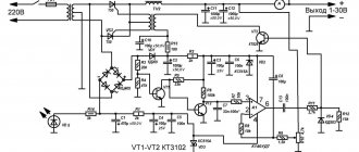
Electromechanical relay protection designs are constantly being modernized and improved. Innovative technological developments and projects are being introduced. The latest energy systems combine static, induction, electromagnetic devices with microprocessor and semiconductor elements.
However, the basic meaning and operating procedure of relay protection for all new devices remains unchanged. The relay protection structure diagram is shown in the figure.
1 — Electrical signal 2 — Electrical process monitoring block 3 — Logic and analysis block 4 — Execution block
5 - Signal block
Observation unit
The main function of this unit is to monitor the electrical processes occurring in the electrical system by measuring devices such as voltage and current transformers.
Output signals on the block can be sent directly to the logic block to compare parameters with user-configured deviation values, called setpoints. Also, the signals from the surveillance unit can first be converted into digital form and then transmitted further.
Logic block
In this block, the received signals are compared with the limiting setpoint values. Even a slight coincidence of these parameters leads to a command to trigger the protection.
Executive block
This block is always in a state ready to operate when a command is received from the logic block. When triggered, the electrical installation circuit is switched according to a planned algorithm, which is based on the principle of preventing electrical equipment malfunctions and electric shock to workers.
Signal block
In the electrical system, all processes occur very quickly, so a person is not able to perceive them. To save events occurring in the system, special signaling devices are used. Which work by sound and visual notification, and also save all occurring events in the device’s memory.
All types of devices, after they are triggered, are manually reset by the operator. This allows you to reliably save information about the operation of automation and relay protection.
Work principles
Relay protection may have disturbances in its performance, which are expressed by the following factors:
To eliminate failures during the operation of relay protection, special requirements are developed for it during design, installation, configuration with commissioning, and maintenance:
Reliability principle
This principle is defined:
Each of these factors has its own assessment.
Maintenance and operation of relay protection has three options for reliability when triggered:
The reliability of protection devices is:
Sensitivity principle
This principle makes it possible to determine the types of expected design damage and abnormal modes of the energy system in the working protection zone.
Kch = Iкз min/Iсз
To determine its numerical value, the Kch coefficient is used. The coefficient is calculated by the ratio of the smallest short-circuit current of the working area to the magnitude of the operating current. Relay protection operates in normal mode when:
Iсз https://electrosam.ru/glavnaja/jelektrooborudovanie/rozetki-vykljuchateli/releinaia-zashchita/
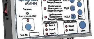
Differential protection of transformers RZL-05.T2, RZL-05.T3
Wide range of protection and automation functions
Digital Oscilloscope Event Log
Integration into SCADA systems
Operating temperature -40°C. +55°C
Possibility of programming logic (on request)
Purpose
Microprocessor relay protection and automation devices of the RZL-05.T are designed to perform the functions of the main protection of a two-winding ( RZL-05.T2 ) or three-winding (or two-winding with a split winding) ( RZL-05.T3 ) transformer or autotransformer with a higher voltage of 35- 110 kV.
The devices are intended for installation in relay compartments of KSO, KRU, KRUN, as well as on panels, in control cabinets of power plants and substations of 35-110 kV.
Download detailed description of RZL-05.T
Functions
- Two stages of longitudinal differential protection - differential current cut-off (DTO) and sensitive differential current protection (DTZ) with braking from through current and detuning from magnetizing current surges (with blocking at the second, third and fifth harmonics during a magnetizing current surge). The DTO works without any blocking and has no braking. For the DTZ stage, braking is performed from all phase current channels.
- Monitoring the health of current circuits (CTC). For timely detection of faults in differential protection current circuits, for example, due to insulation failure or incorrect connection of current circuits, an unbalance alarm is provided in the differential protection arms.
- 5 stages of maximum current protection, incl. current cut-off (TO) and transformer overload protection (TOP) with independent and dependent time-current characteristics, with blocking against magnetizing current surge, with selection of operation in the direction of power. It is possible to implement a combined start based on current and minimum voltage (voltmeter blocking) for MTZ stages.
- Logical busbar protection (LBP) for quick shutdown of the LV HV circuit breaker when a fault occurs on the busbars.
- 3 stages of protection against ground faults in transformer HV circuits based on the measured and calculated zero-sequence current 3I0 of the HV side.
- Protection against open-phase mode (OPF) for negative sequence current.
- External (gas) protection of the transformer. The gas protection of the transformer is triggered by signals from the assigned discrete inputs and acts on the trip relay or alarm.
- Arc protection (AgP) with VOD sensors with the ability to control current.
- Breaker failure redundancy (CBF).
- Freely programmable logic (FPL), which allows you to freely program all discrete inputs, outputs and LEDs of the device.
- Non-volatile event log (256 events).
- Emergency oscilloscope. When the protection is triggered, the device records instantaneous values of input analog (user-selectable) and discrete signals (input, output, signs of protection operation).
- Temperature control inside the device.
- Monitoring the status of the device's discrete inputs.
Braking characteristic of differential protection
The response characteristic (braking characteristic) determines the ratio of differential (Idiff) and braking (Irest) currents. Broken line A-B-C-D
divides the plane into two parts - the area of operation and non-action.
Everything that lies above the broken line is a trigger area
.