Purpose and scope of RCD
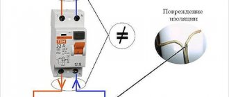
The RCD is designed to compare the amount of electric current flowing in the phase and neutral wires. During normal operation of electrical appliances, this value is the same and the counter currents in the RCD windings compensate each other. As soon as an emergency situation occurs - the insulation is broken somewhere with the subsequent flow of charged particles to the ground, bypassing zero, the differential currents will differ and the protection will turn off the power.
In practice, this can be represented as follows: if the electrical wiring breaks down on the body of a washing machine or water heater, their body will be at potential. As soon as the potential begins to flow from the body to the ground, the protection will react and the person will not be harmed. It is most important to connect an RCD to a circuit of powerful appliances in the kitchen or bathroom, because of the release of condensation on their surface and metal body, which is a potential conductor.
But this does not mean that other equipment does not require similar devices for protective shutdown: the same lamps, sockets and other connected loads can also pose a threat to humans. Therefore, it is also important to connect them to the RCD on the panel, both common for all electrical wiring, and separately for any devices or their groups. Features of the use of electronic and electromechanical RCDs directly depend on the power supply circuit and the location of their installation.
Connection diagrams for RCDs in a single-phase network
Most household consumers are powered by a single-phase circuit, where one phase and neutral conductor is used to supply them with electricity.
Depending on the individual characteristics of the network, single-phase power supply can be provided according to the following scheme:
- with a solidly grounded neutral (TT), in which the fourth wire acts as a return line and is additionally grounded;
- with combined neutral and protective conductor (TN-C);
- with separated zero and protective grounding (TN-S or TN-CS; when connecting devices indoors, you will not find any difference between these systems).
It should be noted that in the TN-C system, in accordance with the requirements of clause 1.7.80 of the PUE, the use of differential circuit breakers is not allowed, except for the protection of individual devices with the obligatory combination of zero and ground from the device to the RCD. In any situation, when connecting an RCD, the characteristics of the supply network should be taken into account.
Without grounding
Since not all consumers can boast of having a third wire in their wiring, residents of such premises have to make do with what they have. The simplest circuit for connecting an RCD is to install a protective element after the input circuit breaker and the electric meter. After the RCD, it is important to connect circuit breakers for different loads with the corresponding shutdown current. Please note that the operating principle of RCDs does not provide for disconnecting current overloads and short circuits, so they must be installed together with circuit breakers.
Rice. 1: Connecting an RCD in a single-phase two-wire system
This option is relevant for apartments with a small number of connected devices. Since if there is a short circuit in any of them, shutting down will not bring any noticeable inconvenience, and finding the damage will not take much time.
But, in cases where a sufficiently branched power supply circuit is used, several RCDs with different operating current values can be used.
Rice. 2: connecting an RCD in a branched single-phase two-wire system
In this connection option, several protective elements are installed, which are selected according to the rated current and operation current. As general protection, an incoming 300 mA fire protection RCD is connected here, followed by a neutral and phase cable to the next 30 mA device, one for sockets, and the second for lighting; a pair of 10 mA units are installed for the bathroom and nursery. The lower the response rating is used, the more sensitive the protection will be - such RCDs will operate at a significantly lower leakage current, which is especially important for two-wire circuits. However, it is also not worth installing sensitive automation on all elements, since it has a high percentage of false positives.
With grounding
If there is a grounding conductor in a single-phase system, the use of an RCD is more appropriate. In such a scheme, connecting the protective wire to the device body creates a path for current leakage if the insulation of the wires is broken. Therefore, the protection will operate immediately in the event of damage, and not in the event of electric shock to a person.
Rice. 3: Connecting an RCD in a single-phase three-wire system
Look at the figure; the connection in a three-wire system is made in the same way as a two-wire system, since only a neutral and phase conductor are required for the device to operate. The grounding device is connected only to the protected objects through a separate grounding bus. Zero can also be connected to a common zero bus; from the zero contacts it is routed by wires to the corresponding devices connected to the network.
As in a two-wire single-phase circuit, with a large number of consumers (air conditioner, washing machine, computer, refrigerator and other amenities of civilization), an extremely unpleasant option is the freezing of all of the above electronic circuits with loss of data or disruption of their functionality. Therefore, several RCDs can be installed for individual devices or entire groups. Of course, connecting them will result in additional costs, but will make finding damage a more convenient procedure.
Technical characteristics of RCD
Decoding of the main parameters of the RCD, which include:
- Type of protected electrical wiring: single-phase or three-phase. This characteristic determines the number of poles (two, four).
- Rated voltage value:
- 220 – 240 V for 2-pole devices;
- 80 – 400 V for 4-pole.
- Current load (nominal). This characteristic corresponds to that of automatic switches (hereinafter AB), but has a different purpose.
- Rated value of the disconnecting electric current with typical values: 10, 30, 100, 300 mA.
Approved residual current symbols:
- AC – sinusoidal alternating current. Its gradual increase and sudden occurrence are acceptable.
- A – the ability to observe the leakage of rectified electric current is added to the previous characteristic (AC).
- S – marking on selective devices that have a large (relative to others) response delay.
- G – identical to the previous type (S), but has a shorter delay.
You might be interested in this Power regulator
Specifications
Important information! The value of the rated electric current parameter determines the permissible value of the latter for the RCD. When selecting him, you need to take into account this point: he must be a level higher in comparison with AB on this line.
Connecting an RCD in a two-phase network
Two-phase power refers to non-standard connections, where a converted old-style 127 V transformer was reconnected into a triangle for modern 220 V consumers, which are powered by linear voltage from it.
Rice. 4: Connecting an RCD in a two-phase system
To connect a residual current device to a two-phase circuit, it is necessary to disconnect both wires at the input to the panel, since each of them is under potential. Then each of the phases is connected to the corresponding phase terminals and neutral terminals, further observing their polarity. Unlike a single-phase system, circuit breakers at the output of the RCD must be installed for each line, or they can be replaced with one two-pole one.
Principle of operation
To understand how the protective structure performs its safety functions, you need to understand the operating principle of the RCD and the connection diagram. It has been established that the current from the network passes through the phase conductor through the load and then returns through the neutral wire. The operation of the device is based on this pattern.
You may be interested in: Correct selection of RCD
Important! The operating principle of the RCD is based on comparing the values of the electric current at the output and input of the object, which is protected.
If Iin = Iout, then the device does not respond. As soon as Iin > Iout, the protective structure senses the leak and reacts as a result.
Operating principle of RCD
In other words, the currents passing through the phase and neutral wires must be the same (for a single-phase network). When the network is three-phase, then the value in the neutral is equal to the sum of the electric currents flowing in the phases. The inequality of electric currents indicates a leak, to which the device reacts.
Connecting an RCD in a three-phase network
Protection of devices powered by three phases at once is carried out according to a similar principle, with the difference that the RCD is selected for four outputs. An example of connection is shown in the figure below:
Rice. 5: Connecting an RCD in a three-phase system
As you can see, in this case, the protective device is also connected after the electric meter and the introductory packet. Individual circuit breakers that respond to phase short circuits are already connected behind it, and, if necessary, more sensitive RCDs are connected to create selective operation for certain groups of consumers.
Since installing a separate device for each phase is too expensive, group RCDs are used in three-phase circuits, which work with all elements of the line at once.
RCD trip current
An important function of the RCD is instantaneous operation when leakage currents occur and disconnecting consumers from the network. Therefore, one of its main technical characteristics is the operating current. It is this indicator that determines the performance of the protective device. Maintaining the RCD in good condition involves monthly checking to ensure that the response parameters comply with the established standards.
Methods for checking the operation of an RCD:
- Check upon purchase using a AA battery and a piece of wire. The RCD lever is cocked, and the battery is connected between the ground input and the phase output. If normal, the device should work instantly.
- Using the TEST button, simulating current leakage when pressed. A working device should turn off immediately.
There are other ways to check using light bulbs, resistors, and measuring instruments. The results obtained make it possible to correctly adjust the device, thereby increasing safety when working with electrical equipment and other devices.
Basic mistakes when connecting an RCD
When connecting an RCD, many people make common mistakes that can have very serious consequences for a person. To avoid them, follow these rules:
- the input terminals of the residual current device must be connected only after the corresponding circuit breaker; direct connection to the network is unacceptable;
- observe the correspondence of neutral and phase contacts, their designation is specifically indicated on the housing;
- when installing wiring, carefully follow the diagram, especially for objects with branching, a large number of connected objects and several RCDs for them;
- if there is no grounding conductor in an apartment or house, then it should never be replaced with a wire thrown over heating radiators or water pipes; grounding must be made in accordance with the rules;
- pay attention to the performance characteristics of the purchased devices (rated operating current and shutdown current) and their compliance with the network parameters, for example, if a current of 50A can flow in the line, then the device should be selected at least 63A.
To protect yourself during connection, follow basic electrical safety rules.
Device diagram
First of all, let us present a schematic diagram of the device, indicating its main elements.
RCD diagram
Designation:
- A – Relay that controls the contact group.
- B – Differential CT (current transformer).
- C – Phase winding on the DTT.
- D – Zero winding on the DTT.
- E – Contact group.
- F – Load resistance.
- G – Button that starts testing the device.
- 1 – Phase input.
- 2 – Phase output.
- N – Neutral wire contacts.
Safety regulations
If you decide to connect the RCD yourself, the success and safety of the work performed will depend on your compliance with the safety rules:
- Before starting installation operations, be sure to remove the voltage from the area (after disconnecting it would be a good idea to check the presence of potential with an indicator);
- Take care of the marking of the wires - this will make it much more convenient to connect the device so as not to confuse the leads;
- Be sure to use factory terminals and clamps, and never allow twisting, soldering or other connections with poor contact;
- After installation, check the reliability of the connections and the presence of sufficient insulation on all current-carrying elements;
- When commissioning, be sure to check the functionality by pressing the test button;
- When you first apply voltage to a newly installed device, it may fly apart due to manufacturing defects or installation defects, so it is better not to stand nearby or take measures to protect your eyes.
Before applying voltage after completing installation, be sure to ensure that no one in your household or colleagues touches live elements.