Parametric stabilizer
Its operating principle is based on the properties of semiconductor devices. The current-voltage characteristic of a semiconductor - a zener diode is shown in the graph.
During turn-on, the zener diode's properties are similar to those of a simple silicon-based diode. If the zener diode is turned on in the opposite direction, the electric current will initially increase slowly, but when a certain voltage value is reached, breakdown occurs. This is a mode where a small voltage increase creates a large zener diode current. The breakdown voltage is called stabilization voltage. To avoid failure of the zener diode, the current flow is limited by resistance. When the zener diode current fluctuates from the lowest to the highest value, the voltage does not change.
The diagram shows a voltage divider, which consists of a ballast resistor and a zener diode. A load is connected in parallel to it. When the supply voltage changes, the resistor current also changes. The zener diode takes over the changes: the current changes, but the voltage remains constant. When you change the load resistor, the current will change, but the voltage will remain constant.
Transistor and Zener diode circuit
Connecting a key element to a simple zener diode device allows you to increase the load current with minimal difficulty. The use of a field-effect transistor instead of a bipolar one makes it possible to reduce power dissipation and reduce the drop at semiconductor junctions, thus increasing the efficiency of the design.
Which voltage stabilizer to choose depends on the requirements for the load current value, stabilization coefficient, and design dimensions.
This largely depends on personal preference. Compensation and parametric devices are easy to understand, easy to assemble and configure. Pulse devices are more technically complex. Although there are many off-the-shelf switching regulator ICs available, lack of a clear understanding of their operation can make troubleshooting difficult. A design selected with a certain current reserve can stand under load for an unlimited time.
Compensation stabilizer
The device discussed earlier is very simple in design, but makes it possible to connect power to the device with a current that does not exceed the maximum current of the zener diode. As a result, voltage stabilizing devices are used, which are called compensation devices. They consist of two types: parallel and serial.
The device is named according to the method of connection to the adjustment element. Compensating stabilizers of the sequential type are usually used. His diagram:
The control element is a transistor connected in series with the load. The output voltage is equal to the difference between the values of the zener diode and the emitter, which is several fractions of a volt, therefore it is considered that the output voltage is equal to the stabilizing voltage.
The considered devices of both types have disadvantages: it is impossible to obtain the exact value of the output voltage and make adjustments during operation. If it is necessary to create the possibility of regulation, then a compensatory type stabilizer is manufactured according to the following scheme:
In this device, regulation is carried out by a transistor. The main voltage is supplied by a zener diode. If the output voltage increases, the base of the transistor becomes negative in contrast to the emitter, the transistor will open by a larger amount and the current will increase. As a result, the negative voltage at the collector will become lower, as well as at the transistor. The second transistor will close, its resistance will increase, and the terminal voltage will increase. This leads to a decrease in the output voltage and a return to its previous value.
When the output voltage decreases, similar processes occur. You can adjust the exact output voltage using a tuning resistor.
Voltage stabilizer using a transistor
If you need to provide a more or less significant load current and reduce its effect on stability, you need to enhance the output current of the stabilizer using a transistor connected according to the emitter follower circuit (Fig. 2).
Rice. 2. Circuit of a parametric voltage stabilizer using one transistor.
The maximum load current of this stabilizer is determined by the formula:
In = (Ist – Ist.min)*h21e.
where Ist. – average stabilization current of the zener diode used, h21e – current transfer coefficient of the base of transistor VT1.
For example, if we use a KS212Zh zener diode (average stabilization current = (0.013-0.0001)/2 = 0.00645A), a KT815A transistor with h21 e - 40), we can get no more current from the stabilizer according to the circuit in Fig. 2: ( 0.006645-0.0001)40 = 0.254 A.
In addition, when calculating the output voltage, you need to take into account that it will be 0.65V lower than the stabilization voltage of the zener diode, because the silicon transistor drops about 0.6-0.7V (approximately take 0.65V).
Let's try to calculate the stabilizer according to the diagram in Figure 2.
Let's take the following initial data:
- Input voltage Uin = 15V,
- output voltage Uout = 12V,
- maximum current through the load In = 0.5A.
The question arises, what to choose - a zener diode with a large average current or a transistor with a large h21e?
If we have a KT815A transistor with h21e = 40, then, following the formula In = (Ist -Ist.min)h21e, we will need a zener diode with a difference between the average current and the minimum current of 0.0125A. In terms of voltage, it should be 0.65V greater than the output voltage, that is, 12.65V. Let's try to find it from the reference book.
Here, for example, is a KS512A zener diode, its stabilization voltage is 12V, the minimum current is 1 mA, the maximum current is 67 mA. That is, the average current is 0.033A. In general it is suitable, but the output voltage will not be 12V, but 11.35V.
We need 12V. It remains to either look for a 12.65V zener diode, or compensate for the lack of voltage with a silicon diode, connecting it in series with the zener diode as shown in Figure 3.
Fig.3. Schematic diagram of a parametric voltage stabilizer, supplemented with a diode.
Stabilizers on microcircuits
Such devices in the integrated version have increased characteristics of parameters and properties that differ from similar semiconductor devices. They also have increased reliability, small dimensions and weight, as well as low cost.
Series regulator
- 1 – voltage source;
- 2 – Adjustment element;
- 3 – amplifier;
- 4 – main voltage source;
- 5 – output voltage detector;
- 6 – load resistance.
The adjustment element acts as a variable resistance connected in series with the load. When the voltage fluctuates, the resistance of the adjustment element changes so that compensation for such fluctuations occurs. The control element is influenced by feedback, which contains a control element, a main voltage source and a voltage meter. This meter is a potentiometer from which part of the output voltage comes.
The feedback adjusts the output voltage used for the load, the output voltage of the potentiometer becomes equal to the main voltage. Voltage fluctuations from the main one creates some voltage drop at the regulation. As a result, the output voltage can be adjusted within certain limits by the measuring element. If the stabilizer is planned to be manufactured for a certain voltage value, then the measuring element is created inside the microcircuit with temperature compensation. If there is a large output voltage range, the measuring element is performed behind the microcircuit.
Parallel stabilizer
- 1 – voltage source;
- 2 – regulating element;
- 3 – amplifier;
- 4 – main voltage source;
- 5 – measuring element;
- 6 – load resistance.
If we compare the circuits of stabilizers, then a device of a sequential type has increased efficiency at partial load. A parallel type device consumes constant power from the source and supplies it to the control element and the load. Parallel stabilizers are recommended for use with constant loads at full load. The parallel stabilizer does not create a danger in the event of a short circuit, the sequential type does not create a danger during idle. At a constant load, both devices create high efficiency.
RESANTA ASN-50000-EM
An electromechanical voltage stabilizer (EMS) is a device that is necessary to have in every home. It is especially needed where the power supply “suffers” from dips and surges in the voltage level in the network. Modern electrical and electronic household appliances are sensitive to the slightest changes in current characteristics. EMC successfully copes with these power supply deficiencies.
More homemade products: How to re-glue the protective glass on your phone - photos with steps
What is better: to make a voltage stabilizer with your own hands or is it better to purchase a ready-made device? Everyone decides for themselves.
, R2off
,
R1on
and
R1off
. The 5th bit of port C is used in the program to send a clock pulse to the oscilloscope so that the results of the experiment can be viewed.
This information interested me, I remembered that in the cinematograph “Ukraine” there was also continuous voltage switching - there, during the switching period, a wirewound resistor was connected between adjacent contacts of the switch. I started looking on the Internet for anything useful about this. I was not able to familiarize myself with invention No. 2356082.
Stabilizer on a chip with 3 pins
Innovative variants of sequential stabilizer circuits are made on a 3-pin microcircuit. Due to the fact that there are only three outputs, they are easier to use in practical applications, since they displace other types of stabilizers in the range of 0.1-3 amperes.
- Uin – raw input voltage;
- U out – output voltage.
You may not use containers C1 and C2, but they allow you to optimize the properties of the stabilizer. Capacity C1 is used to create system stability, capacitance C2 is needed for the reason that a sudden increase in load cannot be tracked by the stabilizer. In this case, the current is supported by capacitance C2. In practice, 7900 series microcircuits from Motorola are often used, which stabilize a positive voltage value, and 7900 – a value with a minus sign.
The microcircuit looks like:
To increase reliability and create cooling, the stabilizer is mounted on a radiator.
Which stabilizer to use in a car
Nowadays, car enthusiasts often modernize the lighting equipment of their cars, using LEDs or LED strips for these purposes (read how to connect an LED strip to a car). It is known that the voltage of a car’s on-board network can vary greatly depending on the operating mode of the engine and generator
Therefore, in the case of a car, it is especially important to use not a 12-volt stabilizer, but one designed for a specific type of LED
For a car, we can recommend designs based on LM317. You can also use one of the modifications of a linear stabilizer with two transistors, in which a powerful N-channel field-effect transistor is used as a power element. Below are options for such circuits, including the LED driver circuit.
Manufacturing of power transformer
The power supply transformer T1, as mentioned above, is one of the main elements of the voltage stabilizer, so its manufacture should be taken responsibly. But making it yourself is very problematic.
Therefore, for greater simplicity, you can purchase 2 finished products of the TPK-2-2 brand. The output voltage of each converter is 12 V, to obtain 24 V, the transformers must be connected in series. The connection diagram is shown below (Figure 3).
Unfortunately, the T2 transformer cannot be purchased, but only made independently. To do this you will need:
The conclusions of the autotransformer, starting from the bottom, are made from: 150, 164, 180, 196, 218 and 246 turns.
Purpose and principle of operation
What is a voltage converter. This is the name given to an electronic device that changes the magnitude of the input signal. It can be used as a device to increase or decrease its value. The input voltage after conversion can change both its magnitude and frequency. Such devices that change DC voltage (convert it) into an AC output signal are called inverters.
Voltage converters are used both as a stand-alone device that supplies consumers with alternating current energy, and can be included in other products: uninterruptible power supply systems and supplies, devices for increasing direct voltage to the required value.
Inverters are harmonic voltage generators. Using a special control circuit, a DC source is created to periodically switch polarity. As a result, an alternating voltage signal is generated at the output contacts of the device to which the load is connected. Its magnitude (amplitude) and frequency are determined by the elements of the converter circuit.
The control device (controller) sets the source switching frequency and the shape of the output signal, and its amplitude is determined by the elements of the output stage of the circuit. They are designed for the maximum power consumed by the load on the AC circuit.
The controller is also used to regulate the magnitude of the output signal, which is achieved by controlling the duration of the pulses (increasing or decreasing their width). Information about changes in the value of the output signal at the load enters the controller via a feedback circuit, on the basis of which a control signal is generated in it to save the necessary parameters. This technique is called PWM (pulse width modulation) of signals.
In the circuits of power output switches of a 12V voltage converter, powerful composite bipolar transistors, semiconductor thyristors, and field-effect transistors can be used. Controller circuits are implemented on microcircuits, which are ready-to-use devices with the necessary functions (microcontrollers), specially designed for such converters.
The control circuit ensures the sequence of operation of the keys to provide at the inverter output the signal necessary for the normal operation of consumer devices. In addition, the control circuit must ensure symmetry of the half-waves of the output voltage
This is especially important for circuits that use step-up pulse transformers at the output. For them, the appearance of a constant voltage component, which can appear when symmetry is broken, is unacceptable
There are many options for constructing voltage inverter (IN) circuits, but there are 3 main ones:
- IN transformerless bridge;
- transformer IN with neutral wire;
- bridge circuit with transformer.
Each of them finds application in its own area, depending on the power source used in it and the required output power to power consumers. Each of them must have protection and alarm elements.
Protection against undervoltage and overvoltage of the DC source determines the operating range of the inverters “at the input”. Protection against high and low output alternating voltage is necessary for the normal operation of consumer equipment. The operating range is set according to the requirements of the load used. These types of protection are reversible, that is, when the equipment parameters are restored to normal, operation can be restored.
When protection is triggered due to a short circuit in the load or an excessive increase in output current, a thorough analysis of the causes of this event is necessary before continuing to operate the equipment.
The 12V converter is the most suitable for creating a local power network. The availability of a large number of vehicles and 12V DC batteries allows them to be used to meet user demands. Such networks can be created in a variety of places, starting from your own car. They are mobile and do not depend on the parking location.
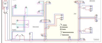
Connection instructions in the panel
First of all, install a three-position switch in the electrical panel, immediately after the input circuit breaker.
- in the first position, when the tongue is raised up, voltage will be supplied to the house directly from the electrical network, without using a stabilizer
What if it breaks down or you need to carry out some revision work. You won’t have to unplug the wires every time and cut off power to the entire apartment.
- in the second position II (the tongue of the machine looks down) - the power supply will go through the stabilizer
- position “0” – all electrical appliances are disconnected, both from the stabilizer and from the external network
Choose a location for installing the voltage stabilizer. You can’t put it anywhere either. There are certain rules that must be followed.
Lay two VVGnG-Ls cables from the panel to this place.
It is advisable to mark each of them and make appropriate inscriptions at both ends:
- stabilizer input
- output from stabilizer
Remove the insulation from the wires and first connect the cable in the electrical panel. Connect the phase from the wire that goes to the input of the stabilizer to the output terminals of the input circuit breaker.
Next, deal with the stabilizer-output cable. Connect the phase conductor (let it be a white wire) to contact No. 2 on the three-position switch.
You connect the neutral and ground from both cables to the appropriate busbars.
Now you need to feed the phase directly from the input machine to the three-position one. You strip the installation wire of the PUGV, terminate the wires with NShVI lugs and lead it from the phase output of the input circuit breaker to terminal No. 4 of the switch.
All that remains to be done in the panel is to power all the machines from terminal No. 1 of the three-position switch.
You perform this operation again with flexible mounting wires.
Thus, according to the diagram, you supplied a phase from the input circuit breaker to the 3-position one, and then distributed the load through its contacts, by connecting through a stabilizer (contact No. 2-No. 1) and directly without it (contact No. 4-No. 1).
In your specific case, these contact numbers may not match the numbers shown here! Be sure to clarify everything in the instructions or in the passport for the machine.
Basic configuration
The main task of the stabilizer is to ensure constant output voltage and suppress ripple. The design of the stabilizer is based on the simplest circuit, but I chose each of its elements so that it ideally fulfills its function:
To maximize input noise suppression, the resistance of the resistor R should be as high as possible, and the internal resistance of the reference voltage source Vref should be as low as possible. And the reference voltage driver will work better if it is powered from a high-resistance source. A stable current source (GST) meets these requirements.
For the high-voltage stabilizer, I used a GST with two transistors, which provides greater current stability when the supply voltage fluctuates.
For low-voltage stabilizers, you can use a similar circuit or just a single diode.
For high-voltage stabilizers, I chose a GST current value of about 5mA. For low-voltage stabilizers, you can choose a lower value.
The TL431 chip requires a minimum of 2 mA for normal operation.
Important note: The two-transistor GST can sometimes be excited if high-frequency transistors are used. Therefore, I chose MJ340/350 transistors which, as my experience shows, work stably
Zener diodes are quite noisy and also have a poor temperature coefficient. The output voltage when using them will vary depending on the ambient temperature, and even more so if your amplifier has active ventilation. In addition, the stability of their internal resistance also leaves much to be desired.
I used a TL431 as a voltage reference instead, as their noise performance is quite decent, they have low output impedance and a fairly wide output voltage range that can be set using a simple divider.
Switching power supply with microcircuit
The diagram of a power supply with a microcircuit from the same company Power Integration is shown in Fig. 6. The device uses a semiconductor voltage limiter - 1.5KE250A.
The converter provides galvanic isolation of the output voltage from the mains voltage. With the ratings and elements indicated in the diagram, the device allows you to connect a load that consumes 20 W at a voltage of 24 V. The efficiency of the converter approaches 90%. Conversion frequency - 100 Hz. The device is protected from short circuits in the load.
Rice. 6. Circuit diagram of a 24V switching power supply on a microcircuit from Power Integration.
The output power of the converter is determined by the type of microcircuit used, the main characteristics of which are given in Table 1.
Table 1. Characteristics of TOP221Y - TOP227Y series microcircuits.
| Chip type | Рmax, W | Protection current, A | Open transistor resistance, Ohm |
| TOP221Y | 7 | 0,25 | 31,2 |
| T0P222Y | 15 | 0,5 | 15,6 |
| T0P223Y | 30 | 1 | 7,8 |
| T0P224Y | 45 | 1,5 | 5,2 |
| T0P225Y | 60 | 2 | 3,9 |
| T0P226Y | 75 | 2,5 | 3,1 |
| T0P227Y | 90 | 3 | 2,6 |
Simple DIY CH
A 12-volt voltage stabilizer for LEDs, backlights of automotive on-board systems is quickly and conveniently performed using microcircuits: LM317, LD1084, L7812, KREN 8B and similar devices. Several diodes, a resistance and the microcircuit itself are the components of such a circuit.
Stabilizer on LM317
Depending on the manufacturing option of the LM317 case, the arrangement of parts on the board is selected.
Making a stabilizer comes down to the following:
- a resistance with a nominal value of 130 Ohms is soldered to the output (Vout);
- a wire supplying voltage for stabilization is connected to the input contact (Vin);
- the adjustment input (Adj) is connected to the second terminal of the resistor.
When connecting LED lights, strips, etc. as a load. no radiator required. Assembly takes 15-20 minutes with a minimum of parts. Using a simple formula, you can calculate the value of resistance R to obtain a certain value of the permissible load current.
Circuit on the LD1084 chip
The use of this microassembly will help maintain the 12 V voltage constant for LED illumination devices connected to the vehicle’s on-board network.
Here, to assemble a homemade CH, the following is included in the circuit binding circuit of the microcircuit:
The device is assembled as follows:
- the voltage removed from the rectifier diode bridge is supplied to the input of LD1084;
- the emitter of the KT818 transistor is connected to the contact that controls the stabilization mode (Adj), the base of which is connected through two single-column resistors to the power supply circuits for the headlights (low and high);
- the output circuit of the microcircuit is connected to resistors R1 and R2, as well as a capacitor.
By the way. Resistor R2 can be taken not as a variable, but as a tuning one, using it to set the output voltage to 12 V.
Stabilizer on diodes and assembly L7812
A similar microcircuit in conjunction with a diode and capacitors can supply LEDs with a stable voltage of 12 V.
The scheme is built according to the principle outlined below:
- The 1N401 Schottky diode passes current from the positive terminal of the battery through itself and supplies it to the input of the microcircuit. In this case, the “+” of the electrolyte (330 μF capacitor) is also connected to the cathode of the diode;
- a load circuit and a “+” capacitor with a capacity of 100 μF are connected to the output of L7812;
- all negative terminals (from the battery and both electrolytic capacitors) are connected to the control input of the microcircuit.
Expert opinion
It-Technology, Electrical power and electronics specialist
Ask questions to the “Specialist for modernization of energy generation systems”
On KRENK, element VD1 is included in the circuit when the values are in the range from 8 to 15 V and are so large that the transistor may fail. Ask, I'm in touch!
Why is current and voltage stabilization necessary?
- The voltage stabilization range from 1.7 to 37 V will ensure stable LED brightness, independent of engine speed;
- Support for output current up to 1.5 A allows you to connect several photo emitters;
- High stability allows fluctuations in output parameters of only 0.1% of the nominal value;
- Has built-in current limiting protection and a shutdown cascade for overheating;
- The microcircuit body is ground, so when fastened with a self-tapping screw to the car body, the number of mounting wires is reduced.