Carrying out complex calculations
For a more detailed and reliable calculation of voltage losses on the line, it is necessary to take into account the reactive and active resistance, which together forms a complex resistance, and power.
To calculate the voltage drop in a cable, use the formula: To calculate the voltage drop in a cable, use the formula:
∆U = (P*r0+Q*x0)*L/ U nom
This formula contains the following values:
- P, Q - active, reactive power.
- r0, x0 - active, reactance.
- U nom - rated voltage.
There are three load connection options:
- from the electrical panel to the end of the line;
- from the electrical panel with uniform distribution along the cable length;
- from the electrical panel to two combined lines with uniform load distribution.
An example of calculating voltage losses: the total power consumption of all volatile installations in a house or apartment is 3.5 kW - the average value for a small number of powerful electrical appliances. If all loads are active (all devices are connected to the network), cosφ = 1 (the angle between the current vector and the voltage vector). Using the formula I = P/(Ucosφ), the current strength is I = 3.5*1000/220 = 15.9 A.
Further calculations: if you use a copper cable with a cross section of 1.5 square meters. mm, resistivity 0.0175 Ohm*mm2, and the length of the two-core cable for wiring is 30 meters.
According to the formula, the voltage loss is:
∆U = I*R/U*100%, where the current is 15.9 A, the resistance is 2 (two wires)*0.0175*30/1.5 = 0.7 Ohm. Then ∆U = 15.9*0.7/220*100% = 5.06%.
The obtained value slightly exceeds the drop of five percent recommended by regulatory documents. In principle, you can leave the diagram for such a connection, but if the main values of the formula are affected by an unaccounted factor, the losses will exceed the permissible value.
What does this mean for the end consumer? Payment for used electricity supplied to the distribution panel at full capacity when actually consuming lower voltage electricity.
Ways to reduce power losses in cables
Losses can be reduced in several ways:
- increasing the cross-sectional area of the cable;
- decreasing the length of the material;
- load reduction.
Often the last two points are more difficult, and therefore you have to do this by increasing the cross-sectional area of the electric cable core. This will help reduce resistance. This option has several costly aspects. Firstly, the cost of using such material for multi-kilometer systems is very significant, and therefore it is necessary to choose a cable of the correct cross-section in order to reduce the threshold of power loss in the cable.
Online calculation of voltage losses allows you to do this in a few seconds, taking into account all additional characteristics. For those who want to double-check the result manually, there is a physical and mathematical formula for calculating voltage losses in a cable. Of course, these are excellent assistants for every electrical network designer.
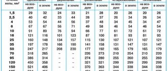
Table for calculating wire cross-section by power
| Cable cross-section, mm2 | Open wiring | Gasket in channels | ||||||||||
| Copper | Aluminum | Copper | Aluminum | |||||||||
| Current | power, kWt | Current | power, kWt | Current | power, kWt | Current | power, kWt | |||||
| A | 220V | 380V | A | 220V | 380V | A | 220V | 380V | A | 220V | 380V | |
| 0,5 | 11 | 2,4 | – | – | – | – | – | – | – | – | – | |
| 0,75 | 15 | 3,3 | – | – | – | – | – | – | – | – | – | |
| 1,0 | 17 | 3,7 | 6,4 | – | – | 14 | 3,0 | 5,3 | – | – | – | |
| 1,5 | 23 | 5,0 | 8,7 | – | – | 15 | 3,3 | 5,7 | – | – | – | |
| 2,0 | 26 | 5,7 | 9,8 | 21 | 4,6 | 7,9 | 19 | 4,1 | 7,2 | 14,0 | 3,0 | 5,3 |
| 2,5 | 30 | 6,6 | 11,0 | 24 | 5,2 | 9,1 | 21 | 4,6 | 7,9 | 16,0 | 3,5 | 6,0 |
| 4,0 | 41 | 9,0 | 15,0 | 32 | 7,0 | 12,0 | 27 | 5,9 | 10,0 | 21,0 | 4,6 | 7,9 |
| 6,0 | 50 | 11,0 | 19,0 | 39 | 8,5 | 14,0 | 34 | 7,4 | 12,0 | 26,0 | 5,7 | 9,8 |
| 10,0 | 80 | 17,0 | 30,0 | 60 | 13,0 | 22,0 | 50 | 11,0 | 19,0 | 38,0 | 8,3 | 14,0 |
| 16,0 | 100 | 22,0 | 38,0 | 75 | 16,0 | 28,0 | 80 | 17,0 | 30,0 | 55,0 | 12,0 | 20,0 |
| 25,0 | 140 | 30,0 | 53,0 | 105 | 23,0 | 39,0 | 100 | 22,0 | 38,0 | 65,0 | 14,0 | 24,0 |
| 35,0 | 170 | 37,0 | 64,0 | 130 | 28,0 | 49,0 | 135 | 29,0 | 51,0 | 75,0 | 16,0 | 28,0 |
How to use an online calculator?
In the finished table you need to enter data according to the selected cable material, system load power, network voltage, cable temperature and method of laying it. Then click the “calculate” button and get the finished result. This calculation of voltage losses in a line can be safely used in work, if you do not take into account the resistance of the cable line under certain conditions:
- When specifying the power factor, cosine phi is equal to one.
- DC network lines.
- AC network with a frequency of 50 Hz made of conductors with cross-sections up to 25.0-95.0.
The results obtained must be used according to each individual case, taking into account all the errors of cable and wire products.
Be sure to fill in all values!
Selection of cable cross-section for voltages up to 1000 V
Selection of cable cross-section for voltages up to 1000 V, regardless of whether it is an electric motor or another load. It comes down to determining long-term permissible currents, that is, a cable cross-section is selected that allows it to withstand long-term design currents for a given section, without causing damage to the cable. The values of permissible continuous currents for cables and wires are indicated in the PUE tables 1.3.4 – 1.3.30, GOST 31996-2012, or use the manufacturer’s catalog data.
Continuously permissible current:
- for electrical receivers:
- for electric motor:
When choosing a cable cross-section, you need to take into account correction factors for ground and air when laying the cable, see PUE tables 1.3.3, 1.3.23, 1.3.26.
The determination of the actual long-term permissible current, taking into account correction factors in accordance with the PUE, is determined by the formula:
Where:
- Id.t. – long-term permissible current for the selected cable cross-section, selected according to GOST 31996-2012 or determined from the manufacturer’s catalogs.
- k1 – correction factor taking into account the temperature of the environment different from the calculated one, selected according to Table 1.3.3 of the Electrical Installation Regulations.
- k2 is a correction factor that takes into account soil resistivity (taking into account geological surveys), selected according to the PUE table 1.3.23.
- k3 – correction factor that takes into account the reduction in current load with the number of operating cables in one trench (in pipes or without pipes), selected according to the PUE table 1.3.26.
In this case, the following condition must be met:
If > Icalc.
Checking the cross-section according to the condition of compliance with the selected device for maximum current protection:
The cross-section of the cable (wire), according to the condition of compliance of the selected device with maximum current protection, is determined by the formula:
Where:
- Idef. – setting current at which the protective device is triggered;
- kdef. – coefficient of multiplicity of the long-term permissible current of the cable (wire) to the operating current of the protective device.
Iprotect value data and kdef. Can be determined from table 8.7 [L5. With. 207].
Checking the section for mechanical strength
The selected cable (wire) cross-section must be no less than that given in the PUE, Table 2.1.1.
Checking the cross section for voltage loss
After you have chosen the cable cross-section for the long-term permissible current, you need to check the cable for permissible voltage losses. That is, the voltage deviation of the pantographs connected to this network did not go beyond the permissible limits.
According to the standards, the following limits of voltage deviations at the terminals of pantographs are allowed [L1. p. 144].
Voltage loss ∆U for a three-phase line is determined by the formulas [L1. from 144]:
1. At the end of the line one load is connected:
2. Several (n) loads are connected along the length of the line:
Where:
- Icalc. – design current, A;
- L – section length, km;
- cosφ – power factor;
- r0 and x0 - the values of active and reactive resistances are determined according to table 2-5 [L2.s 48].
Voltage loss ∆U for a three-phase line can be determined using simplified formulas:
1. At the end of the line one load is connected:
2. Several (n) loads are connected along the length of the line:
Where:
- P – design power, W;
- L – length of the section, m;
- U – voltage, V;
- γ – specific electrical conductivity of the wire, m/Ohm*mm2;
- for copper γ = 57 m/Ohm*mm2;
- for aluminum γ = 31.7 m/Ohm*mm2;
Voltage loss ∆U for direct and single-phase alternating current can be determined using simplified formulas:
1. At the end of the line one load is connected:
2. Several (n) loads are connected along the length of the line:
where: s – cable cross-section, mm2;
Literature:
1. Electrician's reference book. Under the general editorship of V.I. Grigorieva. 2004 2. Design of cable networks and wiring. Khromchenko G.E. 1980 3. GOST 31996-2012 Power cables with plastic insulation for rated voltage 0.66, 1 and 3 kV. 4. Rules for the construction of electrical installations (PUE). Seventh edition. 2008 5. Calculation and design of power supply systems for facilities and installations. Publishing house TPU. Tomsk 2006
All the best! See you again on the Raschet.info website.
Calculation of voltage losses in a cable
In order to ensure the supply of voltage from the distribution device to the end consumer, power lines are used. They can be overhead or cable and have a considerable length.
Like all conductors, they have a resistance that depends on the length and the longer they are, the greater the voltage loss.
In order for the equipment to operate without failures, these losses are normalized. Their total value should not exceed 9%.
The maximum voltage drop at the input is five percent, and to the most remote consumer no more than four percent. In a three-phase network with a three or four wire network, this figure should not exceed 10%.
How to reduce the voltage drop in a cable
Calculation of the inductor
When laying electrical wiring over long distances, the cable cross-section selected for the permissible voltage drop is many times greater than the choice made for heating, which leads to an increase in the cost of power supply. But there are ways to reduce these costs:
- Increase the potential at the beginning of the supply cable. This is only possible when connected to a separate transformer, for example, in a holiday village or microdistrict. If some consumers are disconnected, the potential in the sockets of the rest will be overestimated;
- Installation near the stabilizer load. This requires costs, but guarantees constant network parameters;
- When connecting a 12-36V load through a step-down transformer or power supply, place them near the consumer.
Reference. When the voltage decreases, the current in the network, the voltage drop and the required wire cross-section increase.
Calculation of voltage drop on a wire for direct current
Now, using formula (2), we calculate the voltage drop on the wire:
U = ((ρ l) / S) I , (4)
That is, this is the voltage that will drop on a wire of a given cross-section and length at a certain current.
These are the tabular data for a length of 1 m and a current of 1A:
Table 1. Voltage drop on a 1 m copper wire of different cross-sections and a current of 1A:
| S, mm² | 0,5 | 0,75 | 1 | 1,5 | 2,5 | 4 | 6 | 8 | 10 |
| U, B | 0,0350 | 0,0233 | 0,0175 | 0,0117 | 0,0070 | 0,0044 | 0,0029 | 0,0022 | 0,0018 |
This table is not very informative; it is more convenient to know the voltage drop for different currents and cross sections. Let me remind you that calculations for choosing the wire cross-section for direct current are carried out according to formula (4).
Table 2. Voltage drop for different wire cross-sections (top row) and current (left column). Length = 1 meter
Calculation of voltage drop when feeding consumers with a loop
Calculating the voltage drop when powering consumers using radial circuits is quite simple. One section, one cable section, one length, one load current. We substitute this data into the formula and get the result.
When powering consumers via main circuits (loop), it is more difficult to calculate the voltage drop. In fact, you have to perform several voltage drop calculations for one line: you need to perform a voltage drop calculation for each section. Additional difficulties arise when the power consumption of electrical receivers powered by the main circuit changes. A change in the power of one electrical receiver is reflected in the entire chain.
How common is it in practice to supply power via main circuits and loops? There are many examples that can be given:
- In group networks, these are lighting networks and socket networks.
- In residential buildings, floor panels are powered using main circuits.
- In industrial and commercial buildings, main power supply circuits and panel loop power supply are also often used.
- The busbar is an example of supplying consumers via a trunk circuit.
- Power supply for outdoor road lighting poles.
Let's consider calculating the voltage drop using the example of outdoor lighting. Let's assume that you need to calculate the voltage drop for four outdoor lighting poles, sequentially powered from the ShchNO outdoor lighting panel.
The length of the sections from the shield to the pillar, between the pillars: L1, L2, L3, L4. Current flowing through sections: I1, I2, I3, I4. Voltage drop in sections: dU%1, dU%2, dU%3, dU%4. Current consumed by the lamps on each pole, Ilamp.
The pillars are powered by a loop, respectively:
- I4=Ilamp
- I3=I4+Ilamp
- I2=I3+Ilamp
- I1=I2+Ilamp
The current consumed by the lamp is unknown, but the power of the lamp and its type are known (either from the catalog or according to clause 6.30 of SP 31-110-2003).
The current is determined by the formula:
Formula for calculating total phase current
Iph - total phase current P - active power Uph - phase voltage cosφ - power factor Nph - number of phases (Nph=1 for single-phase load, Nph=3 for single-phase load)
Let me remind you that the linear (phase-to-phase) voltage is √3 times greater than the phase voltage:
When calculating the voltage drop in a three-phase network, the line voltage drop is assumed; in single-phase networks, a single-phase voltage drop is taken into account.
The voltage drop is calculated using the formulas:
Formula for calculating voltage drop in a three-phase circuit
Formula for calculating voltage drop in a single-phase circuit
Iph - total phase current flowing through the section R - section resistance cosφ - power factor
The resistance of the section is calculated using the formula ρ - resistivity of the conductor (copper, aluminum) L - length of the section S - cross-section of the conductor N - number of parallel conductors in the line
Typically, catalogs provide specific resistance values for various conductor cross-sections. If information about the specific resistance of conductors is available, the formulas for calculating the voltage drop take the form:
Formula for calculating voltage drop in a three-phase circuit
Formula for calculating voltage drop in a single-phase circuit
Substituting into the formula the corresponding values of currents, resistivities, length, number of parallel conductors and power factor, we calculate the magnitude of the voltage drop in the section.
Regulatory documents regulate the value of the relative voltage drop (as a percentage of the nominal value), which is calculated using the formula: U - rated network voltage.
The formula for calculating the relative voltage drop is the same for a three-phase and single-phase network. When calculating in a three-phase network, you need to substitute the three-phase drop and rated voltage, when calculating in a single-phase network - single-phase:
Formula for calculating the relative voltage drop in a three-phase network
Formula for calculating the relative voltage drop in a single-phase network
The theory is finished, let's look at how to implement this using DDECAD.
Let's take the following initial data:
- Lamp power 250W, cosφ=0.85.
- The distance between the pillars, from the shield to the first pillar is L1=L2=L3=L4=20m.
- The poles are powered by 3×10 copper cable.
- The branch from the power cable to the lamp is made with a 3×2.5 cable, L=6m.
For each column, we create a calculation table in the DDECAD program.
We fill in the data for the lamp in each calculation table: Connect the calculation table Column 3 to the calculation table Column 3, to Column 2 - Column 3, to Column 1 - Column 2, to SCHO - Column 1:
Next, from the SCHO calculation table, the value of the voltage drop calculated by the program at the end of the first section (Column 1) is transferred to the green cell of the calculation table Column 1:
Values should be transferred by making a reference to the cell of the calculation table of the higher-level panel. In the case of Column 1 and SCHO this is done like this:
- In the calculation table Column 1, the cursor is placed on the green cell in the “∆U” column.
- Click "=".
- Switch to the SCHO calculation table.
- Place the cursor on the cell in the column “∆U∑”, located in the line Column 1.
- Press "Enter".
We get the calculated voltage drop at the end of the second section (Column 2) - 0.37% and the calculated voltage drop across the lamp - 0.27%.
We do the same for all other calculation tables and obtain the calculated values of the voltage drop in all sections. Since we linked the tables (using the program, connecting one table to another, and manually, transferring the voltage drop values), we got a linked system. When you make any changes, everything will be automatically recalculated.
Subscribe and receive notifications of new articles by e-mail
What is voltage drop
When measuring in different parts of a wire through which electric current flows, a change in potential is observed as it moves from the source to the load. The reason for this is the resistance of the wires.
Ohm's law
How is voltage drop measured?
There are three ways to measure fall:
- Two voltmeters. Measurements are taken at the beginning and end of the cable;
- Alternately in different places. The disadvantage of the method is that during transitions the load or network parameters may change, which will affect the readings;
- One device connected in parallel to the cable. The voltage drop in the cable is small, and the connecting wires are long, which leads to errors.
The principle of measuring voltage loss in a cable
What does voltage drop mean?
Drop occurs when load transfer occurs throughout the entire electrical circuit. The action of this load directly depends on the tension parameter in its nodal elements. When the cross-section of the conductor is determined, it is important that its value must be such that during the load it remains within certain limits, which must be maintained for the normal operation of the network.
Mnemonic diagram for Ohm's law
Moreover, the resistance characteristics of the conductors that make up the circuit cannot be neglected. It is, of course, insignificant, but its influence is very significant. The drop occurs when current is transferred. That is why, in order for, for example, a motor or lighting target to operate stably, it is necessary to maintain an optimal level; for this, the electrical circuit wires are carefully calculated.
Important! The limit of the permissible value of the characteristic in question differs from country to country. This cannot be forgotten. If it falls below the values specified in a particular country, wires with a larger cross-section should be used.
Any electrical appliance will work fully if it is supplied with the value for which it is designed. If the wire is taken incorrectly, it will cause large voltage losses and the equipment will operate with reduced parameters. This is especially true for direct current and low voltage. For example, if it is 12 V, then a loss of one or two volts will already be critical.
You might be interested in AC voltage
Ohm's law for a circuit section
What affects the heating of wires?
If the wiring heats up during the operation of household appliances, then you should immediately take all necessary measures to eliminate this problem. There are many factors influencing the heating of wires, but the main ones include the following:
- Insufficient cable cross-sectional area
. To put it in accessible language, we can say this: the thicker the wires of the cable, the more current it can transmit without heating up. The value of this value is indicated in the marking of cable products. You can also measure the cross-section yourself using a caliper (you should make sure that the wire is not live) or by the type of wire. - The material from which the wire is made
. Copper conductors transmit voltage better to the consumer and have lower resistance compared to aluminum conductors. Naturally, they heat up less. - Type lived
. The cable can be single-core (the core consists of one thick rod) or multi-core (the core consists of a large number of small wires). A multi-core cable is more flexible, but is significantly inferior to a single-core cable in terms of the permissible strength of the transmitted current. - Cable laying method
. Tightly laid wires located in the pipe heat up noticeably more than open wiring. - Material and quality of insulation
. Inexpensive wires, as a rule, have low quality insulation, which negatively affects their resistance to high temperatures.
Source
Result of voltage drop
What is the result of this process in a fundamental sense?
Let's see what happens when this characteristic of electrical energy decreases.
In accordance with the regulatory documentation of the PUE, losses during the movement of current from the transformer substation to the most remote area of the electrical load for a populated area should be no more than 9%.
In this case, losses of 4% are allowed from the main input to the electricity consumer, and 5% - from the transformer to the main input.
In three-phase communications, the standard value according to GOST 29322-2014 is 400 V ± 10% during normal operation of the line.
Deviation of this value from the standard can lead to the following results for stationary objects or electrical devices.
- Failures in the operation of electrical installations, improper operation of equipment, its failure, disruption of facility lighting.
- Disconnection of electrical appliances or failures of their correct operation.
- Reduced rotational acceleration of electric motors at start, energy loss, shutdown of devices when heated.
- Incorrect distribution of electrical load from the beginning of the line to the remote end of the wire between consumption objects.
- Work on 50% of room lighting devices.
The normal value for losses under standard operating conditions of a power line is 5%.
This value can be taken for electrical networks at the project stage.
Extended electrical mains are built for high-power currents.
An example of calculating voltage losses in a cable line - SamElectric.ru blog
Main switchboard 2.2. Indications of phase voltages after the first section of the cable line
As you know, the cable cross-section is selected not only by its ability to withstand its maximum current without overheating. Another selection criterion is its length. An important parameter of the power supply system, such as voltage drop, depends on the length. In other words, losses on the cable line.
In household electrical wiring, this problem is practically not taken into account, since it has a significant impact on cable lengths of several tens of meters. Although, I already wrote an article on this topic about voltage drop, but there the main reason for the losses was the high current.
On the Internet this topic is covered very superficially, and when I came across it, it took me a very long time to figure it out. I remembered cosines and sines, found my old calculator)) While I was figuring it out, I wrote this article. As usually happens with me).
In this article I will present calculations and recommendations that I made for a large warehouse complex that was put into operation a year ago.
Why do you need to calculate voltage losses in a cable?
The background is this. The designers were given technical specifications for the power supply project, which indicated the power of the refrigeration systems. While the project was being implemented and money was allocated for its implementation, refrigeration equipment was purchased with a power consumption that was 2 times higher than the original one. In addition, it turned out that the actual distance to the substation will be almost 2 times greater...
In general, expensive German refrigeration equipment refuses to work, everyone knows what to do, but no one wants to pay for it. Last summer, due to low voltage (linear 340-360 V), a compressor worth more than 10 thousand euros burned out. This could no longer be tolerated. I was asked to carry out calculations, monitoring and measurements on the power system, and make recommendations to solve the problem.
Since I wrote this report on behalf of a company that has a license for energy audits, this document will be valid in the upcoming litigation.
As the document progresses, I will provide comments and clarifications in quotes.
An examination was carried out of the quality of electricity supplied from the transformer substation (TS) along the first section (440 m) to main switchboard 2.2 and further along the second sections (50 and 40 m) to the refrigeration units (System 12 and System 14).
Structural diagram of this system:
Diagram of cable lines from transformer substation to load. There is a diesel power plant - a diesel power plant, but is not considered in this case.
The purpose of the survey is to identify the causes of a significant voltage drop on the cable line.
System 12 includes the following consumers:
| Name | Installed power, kW | Max rated current, A |
| Air cooler | 124,6 | 50,5 |
| Air cooler | 78,3 | 27,1 |
| Compressor motors | 100 | 132,7 |
| Fan motors | 13,7 | 29,7 |
| Total | 316,6 | 240 |
System 14 includes the following consumers:
| Name | Installed power, kW | Max rated current, A |
| Air cooler | 234,4 | 81,2 |
| Air cooler | 193,9 | 55,7 |
| Air cooler | 15,2 | 31,3 |
| Compressor motors | 396 | 525,6 |
| Fan motors | 66 | 144,3 |
| Total | 905,5 | 838,1 |
Supply voltage – 380…415 V.
The values of currents, powers and voltages are taken from the passport data of consumers.
- Preliminary calculation of voltage losses in the cable
According to preliminary calculations, when the voltage at the output of the transformer is 415 V at idle (with the load off), at maximum load a drop of 35 V, or 8.43%, is permissible. In this case, at maximum load, the voltage will drop to 380 V, which, according to consumer data sheets, is acceptable.
The transformer substation contains 2 transformers of 600 kW each, which were planned to be used one at a time. But due to the increase in load, they had to be included in parallel.
According to the Code of Rules for the design and construction of SP 31-110-2003, as well as GOST R 50571.15-97, taking into account regulated deviations from the nominal value, the total voltage losses from the busbars of 0.4 kV TP to the most distant load in residential and public buildings should not exceed 9%. Moreover, 5% of them are in the section from the transformer substation to the ASU, and 4% in the section from the ASU to the consumer.
According to GOST 29322-2014, the rated phase voltage in three-phase networks should be 400 V, and under normal operating conditions the supply voltage should not differ from the rated voltage by more than +-10%.
Based on this, a drop of 8.43% is justified and complies with the Rules and GOSTs adopted in the Russian Federation.
- Calculation of voltage drop for the 1st section
During the examination, the following was revealed. From the transformer substation, located at a distance of 440 m, electricity is supplied to Main Switchboard 2.2 via a cable line consisting of four parallel-connected AVBbShv 4x240 cables, with a total cross-section of 960 mm2.
Internals of main switchboard 2.2. At the top is the input from the TP to the input contactor-protective circuit breaker, to the right are the busbars from the automatic transfer switch (reserve - diesel), below is the output circuit breaker, and the outputs to the Systems.
The maximum calculated load current, according to the passport data, is 240 A for System 12 and 838.1 A for System 14. Therefore, the maximum cable line current is 240 + 838.1 = 1078.1 A.
The total installed power, according to the data sheet, is 316.6 kW for System 12, and 905.5 kW for System 14. Therefore, the total installed power of the entire load is 316.6 + 905.5 = 1222.1 kW.
Let's calculate the voltage drop on the cable line of the 1st section from the transformer substation to the main switchboard 2.2 using the formula:
ΔU=√3·I(R·cosφ·L+X·sinφ·L)
Initial data for calculation:
- Maximum current I = 1078.1 A,
- Installed load power 1222.1 kW,
- Specific active resistance of one core R = 0.125 Ohm/km according to the cable manufacturer.
- Specific inductive reactance of one core X = 0.077 Ohm/km according to the cable manufacturer.
- We accept Cosφ = 0.8, then sinφ = 0.6
- Cable core material – aluminum,
- Line length L = 0.44 km.
Substituting the data into the formulas, we find that for one cable the drop will be 239 V, or 57.75%. Then for the existing cable line of the 1st section the voltage drop will be 59.8 V, or 14.43%.
Such a voltage drop in only the 1st section is unacceptable.
This is the basic formula. I did the calculations using a calculator. I checked the received data using the Electrician program (subprogram “Losses”).
In addition, Igor (220blog.ru) helped me a lot, for which I thank him very much!
There is also a good book, I’ll give a link at the end of the article!
Just in case, a table of active and inductive resistances of aluminum and copper cables of different sections:
Table of active and inductive resistances of aluminum and copper cables of different sections
- The result of the survey of the 2nd section (System 12)
After the GRShch2.2 switchboard, the second section of the cable line to System 12, consisting of one AVVG-ng-LS 5×185 cable, 50 m long, goes to the load.
Data for calculation:
- Maximum current 240 A,
- Installed load power 316.6 kW,
- Specific active resistance of one core R = 0.164 Ohm/km according to the cable manufacturer.
- Specific inductive reactance of one core X = 0.077 Ohm/km according to the cable manufacturer.
- Cable core material – aluminum,
- Line length L = 0.05 km.
For an existing cable line, the voltage drop will be 3.67 V, or 0.88%.
- The result of the survey of the 2nd section (System 14)
After the GRShch2.2 switchboard, the second section of the cable line to System 14 goes to the load, consisting of three parallel-connected cables AVVG-ng-LS 5×185 with a length of 40 m.
Data for calculation:
- Maximum current 838.1 A,
- Installed load power 905.5 kW,
- Specific active resistance of one core R = 0.164 Ohm/km according to the cable manufacturer.
- Specific inductive reactance of one core X = 0.077 Ohm/km according to the cable manufacturer.
- Cable core material – aluminum,
- Line length L = 0.04 km.
For one cable, the voltage loss will be 10.2 V, or 2.47%. For the existing cable line of the 2nd section of System 14, the voltage drop will be 3.4 V, or 0.82%.
- Recommendations for upgrading cable lines
For a given maximum current and line length, a different cable line for Section 1 must be selected because the calculated voltage drop for that section is unacceptable. Based on the preliminary calculation data and the voltage drop data in 2 sections, the voltage drop in the 1st section should be no more than 7.55%.
This level of losses will be provided by a cable line consisting of 8 AVBbShv 4x240 cables connected in parallel. That is, add additional cables (4 pieces) to the existing cables (4 pieces).
As a result, the losses on the cable line of section 1 will be 7.2%, or 29.8 V.
The cable lines of 2 sections do not need modernization.
For stable operation of refrigeration equipment, according to its passport data, a voltage with permissible limits of 380 to 415 V is required.
If we take into account the recommendations given, then with an output voltage of the TP of 415 V at maximum load, the voltage loss for System 12 will be 7.2 + 0.88 = 8.08%, or 33.6 V. As a result, at maximum load, the supply voltage of System 12 will be not less than 381.4 V.
For System 14, the losses will be 7.2 + 0.82 = 8.02%, or 33.2 V. As a result, at maximum load, the supply voltage of System 14 will be at least 381.7 V.
- Voltage quality measurement results
The measurements were carried out using a HIOKI 3197 voltage quality analyzer, which allows you to take all voltage parameters online.
The device is designed to plot graphs of various power supply parameters in real time. I have already used HIOKI 3197 in voltage quality analysis for problems with refrigerators. If anyone needs such a device, please contact us!
The measurements were carried out at the connection point of the 2nd section of System 14 in different operating modes of the equipment. The 2nd section of System 12 was not examined because it could not be accessed without turning off the power supply to the TP. But since System 12 is low-power compared to System 14, measurements are sufficient to get an overall picture, the results of which are shown in the graphs below.
Voltage monitoring result
Current monitoring result
Explanations for the graphs.
Peak current consumption (switching on the load at 100% power) occurs at 16:56. In this case, the phase voltage (averaged over phases) is 212 V (linear - 367 V), the current is 836 A.
The transformer is idle (the load is completely turned off) at 17:07. In this case, the phase voltage is 238 V (linear - 412 V), the current is 0 A.
System 12 was turned off when measurements were taken.
Based on the results of the measurements, it can be concluded that the maximum total voltage drop for System 14 is 45 V, or 11%.
These measurements confirm the correctness of the calculations and recommendations made.
Photo of connecting the HIOKI 3197 device to the cable line during the measurement process:
Connecting HIOKI 3197 for real-time voltage measurements
Backup power in the main switchboard 2.2 comes from a diesel power plant (diesel power plant). Switching is done through the ATS (automatic transfer switch) system.
Backup power supply parameters:
- Maximum power of diesel power plant – 600 kW,
- Cable line – 3 cables AVBbShv 4x240, connected in parallel,
- Cable line length – 250 m.
Based on these parameters, we can clearly conclude that the capacity of the diesel power plant and the backup cable line, taking into account the voltage drop, will be enough for no more than half of the maximum load requirements, which is completely unacceptable.
Therefore, it makes no sense to monitor the quality of food through the diesel power station.
For backup power in this case, it is recommended to use a diesel power plant with a power of at least 1220 kW. The cable line must contain 5 AVBbShv 4x240 cables, in which case the voltage drop to the main switchboard 2.2 will be an acceptable value of 6.5%.
Download file
In conclusion - as promised, a good book on calculating voltage loss and voltage loss in a cable. It will be very interesting to everyone who is interested in this article. Nowadays such books are no longer written.
Karpov F. F. How to choose the cross-section of wires and cables, 1973.djvu
I also recommend:
(3 ratings, average: 5.00 out of 5)
samelectric.ru
Calculating the voltage drop
When calculating, be sure to take into account the active and reactive resistance, which make up the complex (total) resistance of the circuit, as well as power.
The formula for calculating this indicator on a section of a chain of length L looks like this:
∆U = (P * r + Q * x) * L / Unom,
Where
- P—active power;
- Q - reactive power;
- r - active resistance;
- x is reactance;
- Unom - rated voltage.
As we said above, in practice deviations from the standard indicator for the PUE are allowed. Permitted deviation limits:
- field lines – ±5%;
- indoor and outdoor household lighting – ±5%;
- industrial lighting (also for public buildings) – from +5% to -2.5%.
As a result of the calculation, we get a percentage indicator.
Voltage loss calculation
Calculation of voltage losses in a cable online. Voltage loss in a cable is a value equal to the difference between the steady-state values of the effective voltage measured at two points of the power supply system (according to GOST 23875-88). If the resistances Zп1=Zп2=Zп3 and Zн1=Zн2=Zн3 are equal, there is no current in the neutral wire (Fig. 1), therefore, for three-phase lines, voltage losses are calculated for one conductor.
In two- and single-phase lines, as well as in a direct current circuit, the current flows through two conductors (Fig. 2), so a coefficient of 2 is introduced (provided that Zп1=Zп2 is equal).
Calculation of linear (between phases) voltage losses in a cable with three-phase alternating current is carried out using the formulas: ΔU(v)=(PRL+QXL)/Uл; ΔU(%)=(100(PRL+QXL))/ Ul² or (if the current is known) ΔU(в)=√3·I(R·cosφ·L+X·sinφ·L); ΔU(%)=(100√3·I(R·cosφ·L+X·sinφ·L))/ Ul, where: Q= Ul·I·sinφ Calculation of phase (between phase and neutral wire) voltage losses in the cable produced by the formulas: ΔU(v)=2·(PRL+QXL)/Uф; ΔU(%)=2·(100(PRL+QXL))/Uф² or (if the current is known) ΔU(в)=2·I(R·cosφ·L+X·sinφ·L); ΔU(%)=2·(100·I(R·cosφ·L+X·sinφ·L))/Uф, where:
Q= Uф·I·sinφ
To calculate line voltage losses U=380 V; 3 phases. To calculate phase voltage losses U=220 V; 1st phase.
For direct current cosφ=1; 1st phase.
P—active power transmitted along the line, W; Q is the reactive power transmitted along the line, VAR; R — specific active resistance of the cable line, Ohm/m; X is the specific inductive resistance of the cable line, Ohm/m; L—cable line length, m; Ul—linear network voltage, V; Uph - phase voltage of the network, V.
comments powered by HyperComments
allcalc.ru
Opportunities for reducing losses
The main way to reduce losses in a cable is to increase its cross-sectional area. In addition, you can reduce the length of the conductor and reduce the load. However, the last two methods cannot always be used due to technical reasons. Therefore, in many cases, the only option is to reduce the cable resistance by increasing the cross-section.
A significant disadvantage of a large cross-section is considered to be a noticeable increase in material costs. The difference becomes noticeable when cable systems stretch over long distances. Therefore, at the design stage, you must immediately select a cable with the required cross-section, for which you will need to calculate the power loss using a calculator. This program is of great importance when drawing up projects for electrical installation work, since manual calculations take a lot of time, and in the online calculator mode the calculation takes literally a few seconds.
Ways to reduce cable losses
In addition to disrupting the normal operation of electrical appliances, a voltage drop in the wires leads to additional energy costs. These costs can be reduced in different ways:
- Increasing the cross-section of the supply wires. This method requires significant costs for cable replacement and careful feasibility testing;
- Reducing line length. A straight line connecting two points is always shorter than a curve or broken line. Therefore, when designing power supply networks, lines should be laid as short as possible;
- Decrease in ambient temperature. When heated, the resistance of metals increases, and electricity losses in the cable increase;
- Reducing the load. This option is possible if there are a large number of consumers and power sources;
- Bringing cosφ to 1 near the load. This reduces current consumption and losses.
Important! All changes must be reflected on diagrams.
For your information. Improving ventilation in cable trays and other structures reduces temperature, resistance and line losses.
To achieve maximum effect, it is necessary to combine these methods with each other and with other energy saving methods.
Calculation of voltage drop and electricity losses in a cable is important when designing power supply systems and cable lines.
Checking the cable for voltage loss
Everyone knows that the flow of electric current through a wire or cable with a certain resistance is always associated with a loss of voltage in this conductor.
According to the rules of the River Register, the total loss of electrical voltage in the main distribution board to all consumers should not exceed the following values:
- for lighting and signaling at a voltage of more than 50 volts - 5%;
- for lighting and signaling at a voltage of 50 volts - 10%;
- for power consumption, heating and heating systems, regardless of electrical voltage – 7%;
- for power consumption with short-term and intermittent operating modes, regardless of electrical voltage – 10%;
- when starting engines – 25%;
- when powering a radio switchboard or other radio equipment or when charging batteries – 5%;
- when supplying electricity to generators and distribution boards - 1%.
Based on this, various types of cables capable of supporting such voltage loss are selected.
Example of a calculator for automating calculations
What is the voltage drop across a section of a circuit?
The operation of electrical appliances is impossible without certain network parameters.
They consist of many factors. One of them is the resistance of conductors to electric current. Considering the cross-section when choosing wires or cables, it is necessary to take into account the voltage drop. Cable conductors will generate heat when current passes. The magnitude of the current, together with the resistance of the cores, determines the level of cable losses. If you have information about the resistance of the cores and how large the current is passing through them, you will be able to find out the amount of losses in the circuit.
Losses are calculated using the formula: ΔU,%=(Unom-U)∙100/Unom. Where, Unom is the rated input voltage, U is the load voltage. Losses are expressed as a percentage of the nominal value characteristic of the voltage encountered.
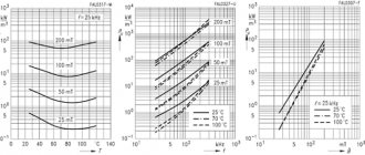
In practice, it is much easier to use Knorring tables, which are in demand when organizing electrical wiring. The information in the tables synchronizes the “load moment” and losses. It is proposed to calculate the torque as the product of load power (P), measured in kilowatts, and linear length (L), indicated in meters. The data in the Knorring tables display the dependence of the losses incurred by the cable on the “load torque”, in relation to two-wire copper lines. A prerequisite is the presence of a voltage of 220V.
A table has also been developed that defines an identical dependence, but in relation to three-phase four-wire neutral lines at a voltage of 380/220V. There is similar information for three-wire lines without zero at 380V. However, the information is reliable only if the load in the phases is equal, which makes it possible to determine the current in four-wire neutral lines, namely in their neutral conductors, as well as zero.
Reasons leading to a decrease in voltage
Voltage losses in power lines occur for the following reasons:
- A current passes through the wire, which heats it, as a result, the active and capacitive resistance increases;
- A three-phase cable with a symmetrical load has the same voltage values on the cores, and the neutral wire current will tend to zero. This is true if the load is constant and purely active, which is impossible in real conditions;
- In networks, in addition to the active load, there is a reactive load in the form of transformer windings, reactors, etc. and as a result, inductive power appears in them;
- As a result, the resistance will consist of active, capacitive and inductive. It affects voltage losses in the network.
Current losses depend on the cable length. The longer it is, the greater the resistance, which means that the losses are greater. It follows that power losses in a cable depend on the length or length of the line.
How to calculate voltage loss
Power calculation
According to Ohm's law, when current flows through a resistance, a potential difference appears across it. In this section of cable, at a current of 53A, permissible with open installation, the drop will be U=I*R=53A*0.425Ohm=22.5V.
For normal operation of electrical equipment, the network voltage should not exceed ±5%. For a household network 220V is 209-231V, and for a three-phase network 380V the permissible fluctuation limits are 361-399V.
When the power consumption and current in electrical cables change, the voltage drop in the conductors and its value near the consumer changes. These fluctuations must be taken into account when designing power supplies.
Selection based on acceptable losses
When calculating losses, it is necessary to take into account that two wires are used in a single-phase network; accordingly, the formula for calculating the voltage drop changes:
U=I*R=(p*2l)/S.
In a three-phase network the situation is more complicated. With a uniform load, for example, in an electric motor, the powers connected to the phase wires compensate each other, the current does not flow through the neutral wire, and its length is not taken into account in the calculations.
If the load is uneven, as in electric stoves, in which only one heating element can be turned on, then the calculation is carried out according to the rules of a single-phase network.
In long-distance lines, in addition to active ones, inductive and capacitive reactance is also taken into account.
Principle of voltage loss formation
The calculation can be done using tables or using an online calculator. In the previously given example, in a single-phase network and at a distance of 100 meters, the required cross-section will be at least 16 mm², and in a three-phase network - 10 mm².
Selection of cable cross-section for heating
The current flowing through the resistance releases energy P, the value of which is calculated by the formula:
Р=I²*R.
In the cable from the previous example, P=40A²*0.425Ohm=680W. Despite the length, this is enough to heat the conductor.
When the wire is heated above the permissible temperature, the insulation fails, which leads to a short circuit. The amount of permissible current depends on the material of the conductor, insulation and installation conditions. To select, you must use special tables or an online calculator.
How to find the voltage drop and correctly calculate its loss in a cable
One of the main parameters by which tension is calculated is the resistivity of the conductor. Copper or aluminum wires are used for wiring from the station or panel to the room. Their resistivity is 0.0175 Ohm*mm2/m for copper and 0.0280 Ohm*mm2/m for aluminum.
The voltage drop for a 12 volt DC circuit can be calculated using the following formulas:
- determination of the rated current passing through a conductor. I = P/U, where P is power and U is rated voltage;
- determination of resistance R=(2*ρ*L)/s, where ρ is the resistivity of the conductor, s is the cross-section of the wire in square millimeters, and L is the length of the line in millimeters;
- determination of voltage loss ΔU=(2*I*L)/(γ*s), where γ is a value that is equal to the inverse resistivity;
- determination of the required cross-sectional area of the wire: s=(2*I*L)/(γ*ΔU).
Important! Thanks to the last formula, you can calculate the required cross-sectional area of the wire for the load and make a verification calculation of losses. Table of inductive reactance values. Table of inductive reactance values
Table of inductive reactance values
In a three-phase network
To ensure optimal load in a three-phase network, each phase must be loaded evenly. To solve this problem, electric motors should be connected to linear conductors, and lamps should be connected between the neutral line and phases.
The loss of electrical voltage in each wire of a three-phase line, taking into account the inductive resistance of the wires, is calculated using the formula
Calculation formula
The first term of the sum is the active, and the second is the passive component of the tension loss. For ease of calculations, you can use special tables or online calculators. Below is an example of such a table, which takes into account voltage losses in a three-phase overhead line with aluminum wires with an electrical voltage of 0.4 kV.
Example table
Voltage loss is determined by the following formula:
ΔU = ΔUtable * Ma;
Here ΔU is the voltage loss, ΔUtable is the value of the relative losses, % per 1 kW km, Ma is the product of the transmitted power P (kW) and the line length, kW km.
Single line diagram of a three-phase current line
On the chain section
In order to measure the voltage loss on a section of the circuit, you should:
- Take a measurement at the beginning of the chain.
- Perform voltage measurements at the most remote area.
- Calculate the difference and compare with the standard value. In case of a large drop, it is recommended to check the condition of the wiring and replace the wires with products with a smaller cross-section and resistance.
Important! In networks with voltages up to 220 V, losses can be determined using a conventional voltmeter or multimeter. A basic way to calculate power loss can be an online calculator, which carries out calculations based on the initial data (length, cross-section, load, voltage and number of phases). A basic way to calculate power loss can be an online calculator that performs calculations based on the initial data (length, cross-section, load, voltage and number of phases)
A basic way to calculate power loss can be an online calculator, which carries out calculations based on the initial data (length, cross-section, load, voltage and number of phases).
We advise you to study - The influence of frequency changes on the operation of electrical systems
Sample calculator for calculating losses
Thus, you can calculate and calculate voltage losses using simple formulas, which for convenience are already collected in tables and online calculators that allow you to automatically calculate the value based on given parameters.
What is voltage loss in a cable and why is it dangerous?
Ideally, all electrical appliances will operate normally if they are supplied with the voltage for which they are designed. If the wire is not calculated correctly and there are large losses in it, then there will be an underestimated voltage at the input to the electrical equipment. This is very important when using DC power, since the voltage here is very low, for example 12 V, and a loss of 1-2 V will be significant.
What is the danger of voltage loss in electrical wiring?
- Failure of electrical appliances to operate at very low input voltage.
When choosing a cable, you need to find a middle ground. It must be selected so that the resistance of the wire at the required length corresponds to a specific current and eliminate unnecessary financial costs.
Of course, you can buy a cable with a huge cross-section and not consider the voltage loss in it, but then you will have to overpay for it.
And who wants to waste their money? Let's figure out below how to take into account voltage losses in a cable when choosing it.
In order to avoid power losses we need to reduce the resistance of the wire. We know that the larger the cable cross-section, the lower its resistance. Therefore, this problem in long lines is solved by increasing the cross-section of the cable cores.
- Let's remember physics and move on to small formulas and calculations.
- We can find out the voltage on the wire using the following formula, knowing its resistance (R, Ohm) and load current (I, A).
- U=RI
- The wire resistance is calculated as follows:
- R=рl/S , where
- p—wire resistivity, Ohm*mm2/m;
- l—wire length, m;
- S is the cross-sectional area of the wire, mm2.
Specific resistance is a constant value. For copper it is p=0.0175 Ohm*mm2/m , and for aluminum p=0.028 Ohm*mm2/m . We do not need the values of other metals, since we only have wires with copper or aluminum conductors.
I will give a small example of calculation for a copper wire. For aluminum wire, the essence of the calculation will be similar.
For example, we want to install a group of sockets in the garage and decided to extend there a copper cable from the house 50 m long with a cross-section of 1.5 mm2. There we will connect a load of 3.3 kW (I=15 A).
- Please note that the current “runs” through a 2-core cable back and forth, so the distance it “travels” will be twice the length of the cable (50*2=100 m).
- The voltage loss in this line will be:
- U=(рl)/s*I=0.0175*100/1.5*15=17.5 V
- Which is almost 9% of the nominal (input) voltage value.
This means that the voltage in the sockets will already be: 220-17.5 = 202.5 V. This will not be enough for the normal operation of electrical equipment. Also, the light may burn dimly (half incandescent).
Power P=UI=17.5*15=262.5 W will be allocated to heat the wire.
Also note that losses at connection points (twists), in the plug of an electrical appliance, and in socket contacts are not taken into account here. Therefore, the actual voltage losses will be greater than the obtained values.
- Let's repeat this calculation, but for a wire with a cross section of 2.5 mm2.
- U=(рl)/s*I=0.0175*100/2.5*15=10.5 V or 4.7%.
- Now let's repeat this calculation, but for a wire with a cross-section of 4 mm2.
- U=(рl)/s*I=0.0175*100/4*15=6.5 V or 2.9%.
- According to the PUE, voltage deviations in the line should be no more than 5%.
- Therefore, in our case, we need to choose a cable with a cross-section of 2.5 mm2 for a load of 3.3 kW (15 A), and not 1.5 mm2.
For direct current, such sections cannot be used at the specified lengths. Assume that you need to power an electrical appliance with a current of 15 A from a 12 V DC source (for example, from a battery or a step-down transformer). A cable with a cross section of 2.5 mm2 and a length of 50 m is used.
The losses here will be 10.5 V. This means that at the input to the electrical device there will be a voltage of 12-10.5 = 1.5 V. This is nonsense and nothing will work. Even a cable with a cross-section of 25 mm2 will not save you. There is only one way out - you need to move the power source closer to the consumer.
If your outlet is located very far from the panel, then be sure to calculate the voltage loss in this line.
Don't forget to smile:
Calling my husband on a business trip: - Dear, why is there no water in the tap? - You see, we live on the 22nd floor and the pressure that the pump creates may not be enough... - Honey, why is there no gas? - You see, it’s winter now and the pressure in the main gas pipeline has been somewhat reduced due to a lot of analysis... - Dear, but why then is there no electricity?!
- Go pay for the utilities, fool!
Permissible voltage loss
Methods for arithmetic calculation of overhead electronic networks with wires made of various materials for voltage loss. The permissible voltage loss in an electronic network is determined by the likely permitted voltage deviations of potential users. Therefore, considerable interest has been given to the consideration of the request for an answer about voltage deviations.
For any receiver of electrical energy, specific voltage drops are possible. For example, non-simultaneous power units in standard standards allow voltage anomalies to be ±5%. This means, therefore, that in a curious incident, if the rated voltage of the provided electric motor is 380 V, from this voltage U'add = 1.05 Un = 380 x 1.05 = 399 V and U'add = 0.95 Un = 380 x 0.95 = 361 V should be based on its most likely permissible voltage indicators. Of course, all buffer voltages, included among the designations 361 and 399 V, will still satisfy the purchasing user and will compose a certain range, one or another, without variations, can be called the range of desired voltages.
Determination of the cross-section of wires or cables based on the permissible voltage loss
The selection of the cross-section of conductors in the cable network must be made according to the permissible voltage loss, which is set in such a way that voltage deviations for all electrical equipment connected to this network do not go beyond the permissible limits.
Rated voltages at the output of power supply systems (according to GOST 21128-83):
According to GOST 13109-97:
- The normally permissible value of steady-state voltage deviation is ±5.
- The maximum permissible value of steady-state voltage deviation is ±10.
Line active and inductive reactance
The active resistance of the line (Ohm/km) is equal to:
When calculating electrical networks based on voltage loss, the active resistance of the wires must always be taken into account. On the contrary, the inductive reactance of the line in some cases can be neglected.
Value of inductive reactance of conductors Calculation of a network based on voltage loss without taking into account the inductive reactance of wires is permissible in the following cases:
- for DC network;
- AC at cosφ = 1
- for networks made with cables or insulated wires laid in pipes on rollers or insulators, if their cross-section does not exceed the values indicated in the table below.
Formulas for calculating the cross-section of conductors for a given voltage loss
Three-phase AC line:
Two-wire AC or DC line:
Where γ is the conductivity of the wire material, m/(Ohm×mm2);
Un — rated network voltage, kV (for a three-phase network Un — phase-to-phase voltage);
∆Uadd – permissible voltage loss in the line, the cross-section of which is determined, %.
F—conductor cross-section, mm2;
∑P∙L=P1∙L1+P2∙L2+…—the sum of the products of the loads flowing along the sections of the line and the length of these sections; loads should be expressed in kilowatts, lengths in meters;
∑Iа∙L= Iа1 ∙L1+ Iа2 ∙L2+…—the sum of the products of the active components of currents passing through the sections and the lengths of the sections;
Currents must be expressed in amperes, lengths in meters.
The active components of the current (A) are determined by multiplying the current values by the power factor values Ia = I∙ cos ɸ.
An example of calculating the minimum cross-section for permissible voltage loss (without taking into account inductive reactance)
Important! It must be remembered that in this calculation we find the value of the minimum cross-section based on the permissible voltage loss across the load; it is also mandatory to check the permissible continuous current (heating of the cable). Table in the PUE (Chapter 1.3)
Example No. 2.
Determine the required cross-section of a two-wire line for spotlights (at the end of the line), using incandescent lamps with a power of 900 W, 3 pieces, total line length 250 m, rated line voltage 220 V, permissible voltage loss UAdd = 5%, aluminum line wires.
Determine the total load:
The sum of the products of the load and the length of the line: ∑P∙L= 2.7 ∙ 250 = 675 kW ∙ m. We substitute the values in formula (7) and determine the cross-sections of the line wires:
Rounding up to the nearest (upwards) standard cross-section (produced by industry), we select the cross-section of the line wires.
Example No. 3.
Determine the cable cross-section for connecting the pump (at the end of the line), using a three-phase asynchronous motor with a mechanical shaft power of 5.5 kW AIR100.
Remember! That the nameplate of the engine does not indicate the electrical power (consumed from the network) but the mechanical power on the shaft (GOST R 52776-2007).
cos ɸ = 0.89, efficiency = 0.848, cable length 130 m, rated line voltage 380 Volts, permissible voltage loss UAdd=5%, line wires are copper.
Thus, for further calculations we need to determine the active component of electrical power:
P2= 5.5/0.848 = 6.485 kW.
We determine the design load of the electric motor (demand coefficient for a single load Kс = 1):
The calculated current is determined by formula (2):
The sum of the products of current and line length: ∑I∙L= 11 ∙ 130 = 1430 A ∙ m. We substitute the values in formula (6) and determine the cross-sections of the line wires:
Rounding up to the nearest (upward) standard cross-section (produced by industry), we determine the cross-section of the line wires to be 2.5 mm2.
And sometimes it is necessary to find out the exact value of the voltage loss in Volts, for this the formula is used:
Let's substitute the values from example No. 3:
And vice versa, if you need to know the percentage of deviation (for example, during practical measurements):
Reduce losses
It is quite obvious that losses depend on the length of the conductor in the line. The higher this parameter is, the more the voltage drops. Several methods can be used to reduce losses:
- Increase the conductor cross-section to evenly distribute the load on the line.
- Reduce the cable length, which is not always possible.
- Reduce the power of current transmitted through a long wire.
The latter method works great in power networks that have several backup lines. It should also be remembered that the voltage may drop as the temperature of the cable increases. If additional thermal insulation measures are used during cable installation, losses can be reduced.
In the energy industry, calculating the voltage drop on the main line is one of the most important tasks. If all calculations were carried out correctly, then the consumer will not have problems with the operation of electrical equipment.
Online calculator for calculating voltage losses in a cable
Long cable lines are characterized by significant resistance, which makes adjustments to the operation of the network. Depending on the brand of cable and other parameters, the resistance value will also differ. And the amount of voltage on the cable line is directly proportional to this resistance.
Using an online calculator, calculating voltage losses in a cable comes down to the following steps:
- Indicate the cable length in meters and the material of the current-carrying conductors in the appropriate boxes;
- Conductor cross-section in mm²;
- The amount of electricity consumed in amperes or watts (place the indicator next to the power or current, depending on what parameter you know and what value you will indicate);
- Enter the voltage value in the network;
- Enter the power factor cosφ;
- Specify the cable temperature;
After you have entered the above data into the fields of the calculator, click the “calculate” button and in the corresponding columns you will receive the calculation result - the amount of voltage loss in the cable ΔU in%, the resistance of the wire itself Rpr in Ohm, the reactive power Qpr in VAR and the voltage at the load Un.
To calculate these values, the entire system, including cable and load, is replaced with an equivalent one, which can be represented as follows:
Line equivalent circuit with load
As you can see in the figure, depending on the type of power supply to the load (single-phase or three-phase), the resistance of the cable line will have a series or parallel connection with respect to the load. Calculation in the calculator is carried out using the following formulas:
Where,
- ΔU – voltage loss;
- UЛ – linear voltage;
- UФ – phase voltage;
- I – current flowing in the line;
- ZK – cable line impedance;
- RK – active resistance of the cable line;
- XK – cable line reactance.
Of these, UЛ, UФ, I, are specified at the data entry stage. To determine the total resistance ZK, the arithmetic addition of its active RK and reactive XK components is performed. Active and reactive resistance is determined by the formulas:
- RК = (ρ * l) / S
- RК – active resistance of the cable line, where
- ρ is the resistivity for the corresponding metal (copper or aluminum), but the value of the resistivity of the material is not constant and can vary depending on the temperature, which is why, to bring it to real conditions, recalculation is performed in relation to temperature:
- ρt = ρ20 *
- Here:
- a is the coefficient of temperature change in the resistivity of the material.
- ρ20 – specific resistance of the material at a temperature of +20ºС.
- t is the actual temperature of the conductor at a given time.
- l – cable line length (if the load is single-phase and the cable has two cores, then both of them are connected in series and the length must be multiplied by 2)
- S – cross-sectional area of the conductor.
- Knowing the active resistance, you can calculate the reactive XK, through the power factor using the following formula:
- Reactive power is determined by the following formula: Q = S*sin φ, where
- Where S is the apparent power, which can be defined as the product of the current in the circuit and the input voltage of the source or as the ratio of active power to power factor.
- To calculate the voltage per load, the following calculations are made: UH = U - ΔU, where
- Where UН is the voltage applied to the load;
- U – voltage at the input to the cable line
- ΔU – voltage drop in the cable line.
Loss Value Calculation
To ensure the operability of the equipment, it is necessary to make a calculation. It is carried out at the time of design. The current level of development of computer technology allows calculations to be made using an online calculator, which allows you to quickly calculate cable power losses.
To calculate, just enter the required data. Set the current parameters - direct or alternating. The power line material is aluminum or copper. Indicate by what parameters the power loss is calculated - by cross-section or diameter of the wire, load current or resistance.
Additionally, indicate the network voltage and cable temperature (depending on operating conditions and installation method). These values are inserted into the calculation table and calculated using an electronic calculator.
You can make a calculation based on mathematical formulas. In order to correctly understand and evaluate the processes occurring during the transmission of electrical energy, a vector form of representing characteristics is used.
And to minimize calculations, a three-phase network is represented as three single-phase networks. Network resistance is represented as a series connection of active and reactive resistance to the load resistance.
In this case, the formula for calculating power loss in a cable is significantly simplified. To obtain the necessary parameters, use the formula.
∆U= I*RL.
This formula shows the power loss of a cable as a function of the current and resistance distributed along the length of the cable.
However, this formula is valid if you know the current strength and resistance. Resistance can be calculated using the formula. For copper it will be equal to p=0.0175 Ohm*mm2/m, and for aluminum p=0.028 Ohm*mm2/m.
Knowing the value of resistivity, calculate the resistance, which will be determined by the formula
R=р*I/S, where р is resistivity, I is line length, S is cross-sectional area of the wire.
In order to calculate voltage losses along the cable length, you need to substitute the obtained values into the formula and perform calculations. These calculations can be made when installing electrical networks or security systems and video surveillance.
If power loss calculations are not made, this may lead to a decrease in the supply voltage to consumers. As a result, the cable will overheat, it may become very hot, and as a result, the insulation will be damaged.
Which may cause electric shock or short circuit to people. A decrease in line voltage can lead to failure of electronic equipment.
Therefore, when designing electrical wiring, it is important to calculate the voltage loss in the supply wires and the laid cable.
Basic formulas for determining voltage
To calculate the voltage and resistance in a circuit, formulas or ready-made online calculators are used.
Through current and resistance
| Meaning | Formula |
| Basic calculation of voltage on a circuit section | U=I/R, where I is the current in Amperes, and R is the resistance in Ohms |
| AC voltage detection | U=I/Z, where Z is the resistance in Ohms, measured along the entire length of the circuit |
Ohm's law has exceptions to its application:
- When high-frequency currents pass, a rapid change in electromagnetic fields occurs. When calculating high-frequency circuits, the inertia of the particles that transfer the charge should be taken into account.
- When circuits operate at low temperatures (near absolute zero), substances may develop the property of superconductivity.
- A conductor heated by passing currents causes variable resistance to appear.
- When exposed to high voltage conductors or dielectrics.
- During processes occurring in semiconductor-based devices.
- When LEDs are working.
Through power and current
With a known consumer power and current strength, the voltage is calculated using the formula U=P/I, where P is the power in Watts, and I is the current strength in Amperes.
When calculating in AC circuits, a different formula is used: U=(P/I)*cosφ, where cosφ is the power factor, depending on the nature of the load.
When using devices with active loads (incandescent lamps, devices with heating coils and elements), the coefficient approaches unity. The calculations take into account the possibility of the presence of a reactive component during operation of the devices and the cosφ value is considered equal to 0.95. When using devices with a reactive component (electric motors, transformers), cosφ is generally considered to be equal to 0.8.
To check the calculations, it is recommended to compare the result with the standard voltage, which is 220 Volts for a single-phase network and 380 Volts for a three-phase network.
Through work and charge
The calculation method is used in laboratory problems and is not used in practice.
The formula has a form similar to Ohm's law: U=A/q, where A is the work done to move the charge in Joules, and q is the passed charge, measured in Coulombs.
Resistance calculation
During operation, a conductor creates an obstacle to the flow of electric current, which is called resistance. In electrical calculations, the concept of resistivity is used, which is measured in Ohm*m.
| Meaning | Formula |
| Calculation of the resistance of one element | R=U/I, where U is voltage in Volts, and I is current in Amperes |
| Calculation for a homogeneous conductor | R=(ρ*l)/S, where ρ is the resistivity value (Ohm*m, taken from tables of values), l is the length of the conductor section (meters), and S is the cross-sectional area (m2) |
Serial connection
In a series connection, the output of an element is connected to the input of the next one. The total resistance is found using the calculation formula: R=R1+R2+…+Rn, where R=R1+R2+…+Rn are the resistance values of the elements in Ohms.
Parallel connection
A parallel connection is a connection in which both terminals of one circuit element are connected to the corresponding contacts of the other. Parallel connection is characterized by the same voltage across the elements. The current across each element will be proportional to the resistance.
The total resistance is calculated using the formula: 1/R=1/R1+1/R2+…+1/Rn.
In real wiring diagrams, a mixed connection is used. To calculate the resistance, you should simplify the circuit by summing up the resistance in each series circuit. The circuit is then reduced by calculating individual sections of the parallel connection.
Voltage drop on wires - distance from transformer to lamps or strip
We are often asked whether it is possible to move 12-volt LED lamps of such and such power in such and such quantity away from the transformer at such and such a distance?
The general recommendation is that this distance should not exceed 5 meters. This is a known fact.
But what if you need more than 5 meters? Often, due to design limitations, it is impossible to meet such a short distance.
Wire losses are the essence of the problem
In some situations, you can turn the number 5 into a much larger value. To do this, you need to estimate the voltage drop across the wires.
This is what causes the limitations - the wire itself has internal resistance and therefore “eats” part of the voltage of the current source. And when the wire is too long, it can happen that the lamps are left with such a small part of the original voltage that they do not light up.
The second part of the problem is that the wire does not just “eat up” part of the voltage, but turns it into heat. In addition to the fact that this is simply a stupid waste of electricity, it also poses a fire problem - the wire can heat up too much.
To be sure that the required, for example, 15 meters between the transformer and the lamp will not cause trouble, you need to estimate exactly how many volts will be lost over these 15 meters.
Calculating the voltage drop across a wire is very simple. As a rule, you have all the data necessary for this: wire length, total power of connected lamps (strips), supply voltage and cross-sectional area of the conductor. You just need to additionally find out the electrical resistivity of the material from which the wire is made.
Formula for calculating voltage drop across wires
It is quite easy to derive a simple general formula for calculating voltage drop, applicable in any situation.
We only need Ohm's law R = V ∕ I and the formula for the relationship between electrical power, voltage and current W = V I.
Also, to estimate the resistance of a wire, you need to know the value of the electrical resistivity [Wikipedia] of the conductor material.
Having carried out simple calculations, we obtain the following formula, which gives an estimate of the value of the voltage drop on the wires:
Estimation of voltage drop on wires
The voltage drop depends on the type of wire material, wire cross-section, its length, consumer power and power source voltage. This formula indicates:
- W is the power in watts of the current consumers at the end of the wire;
- V is the voltage of the current source in volts, usually 12 volts or 24 volts;
- L is the length of the wire in meters, i.e. distance of consumers from the transformer;
- S is the cross-sectional area of the wire in mm²;
- ρ is the value of electrical resistivity in Ohm mm²/m, for copper it is approximately 0.018 Ohm mm²/m
The formula is simple, but only applicable if the expected voltage drop is small, no more than a few percent, i.e. when the distance between the transformer and the consumer does not exceed 10 meters, and the power is less than 10-20 watts.
In other cases, you should use a more precise formula:
The exact voltage drop across the wires
Now, having calculated the voltage drop across the wires, we can estimate how much power will be lost - simply spent on heating the wires. You need to multiply the resulting voltage drop value by the power of current consumers W and divide by the transformer voltage V:
Estimation of power drop on wires
If this power turns out to be too large, then, obviously, you need to increase the thickness of the wire. Otherwise, you can get into various troubles, including a fire.
conclusions
As is easy to see from the formulas, the thicker the wire, the lower the voltage drop.
In this case, the voltage drop is inversely proportional to the cross-sectional area of the conductor.
Another possible solution to the problem may be to increase the voltage value of the current source. If, of course, current consumers allow it.
The voltage drop across the wire decreases linearly with increasing voltage of the current source.
For example, our low-voltage E27 lamps for 12-24 volts produce the same light from both 12 and 24 volts. And in this case, it makes sense to switch to a 24 volt transformer.
It also becomes clear that for powerful consumers (about 100 watts) very thick wires will be needed.
Voltage drop calculations
DC / single phase calculation
The voltage drop V in volts (V) is equal to the wire current I in amps (A) times 2 times one way wire length L in feet (ft) times the wire resistance per 1000 feet R in ohms (Ω/kft) divided by 1000:
Vdrop (V) = Iwire (A) × Rwire(Ω)
= Iwire (A) × (2 × L(ft) × Rwire(Ω/kft) / 1000(ft/kft))
The voltage drop V in volts (V) is equal to the wire current I in amps (A) times 2 times one way wire length L in meters (m) times the wire resistance per 1000 meters R in ohms (Ω/km) divided by 1000:
Vdrop (V) = Iwire (A) × Rwire(Ω)
= Iwire (A) × (2 × L(m) × Rwire (Ω/km) / 1000(m/km))
3 phase calculation
The line to line voltage drop V in volts (V) is equal to square root of 3 times the wire current I in amps (A) times one way wire length L in feet (ft) times the wire resistance per 1000 feet R in ohms (Ω/kft) divided by 1000:
Vdrop (V) = √3 × Iwire (A) × Rwire (Ω)
= 1.732 × Iwire (A) × (L(ft) × Rwire (Ω/kft) / 1000(ft/kft))
The line to line voltage drop V in volts (V) is equal to square root of 3 times the wire current I in amps (A) times one way wire length L in meters (m) times the wire resistance per 1000 meters R in ohms (Ω/km) divided by 1000:
Vdrop (V) = √3 × Iwire (A) × Rwire (Ω)
= 1.732 × Iwire (A) × (L(m) × Rwire (Ω/km) / 1000(m/km))
Wire diameter calculations
The n gauge wire diameter dn in inches (in) is equal to 0.005in times 92 raised to the power of 36 minus gauge number n, divided by 39:
dn (in) = 0.005 in × 92(36-n)/39
The n gauge wire diameter dn in millimeters (mm) is equal to 0.127mm times 92 raised to the power of 36 minus gauge number n, divided by 39:
dn (mm) = 0.127 mm × 92(36-n)/39
Wire cross sectional area calculations
The n gauge wire's cross sercional area An in kilo-circular mils (kcmil) is equal to 1000 times the square wire diameter d in inches (in):
An (kcmil) = 1000×dn2 = 0.025 in2 × 92(36-n)/19.5
The n gauge wire's cross sercional area An in square (in2) is equal to pi divided by 4 times the square wire diameter d in inches (in):
An (in2) = (π/4)×dn2 = 0.000019635 in2 × 92(36-n)/19.5
The n gauge wire's cross sercional area An in square millimeters (mm2) is equal to pi divided by 4 times the square wire diameter d in millimeters (mm):
An (mm2) = (π/4)×dn2 = 0.012668 mm2 × 92(36-n)/19.5