Voltage drop on the wire
The article will be specific, with theoretical calculations and formulas. For those who are not interested in what comes from and why, I advise you to go straight to Table 2 - Selecting the wire cross-section depending on the current and voltage drop.
And also - calculation of voltage losses on a long powerful three-phase cable line. An example of calculating a real line.
So, if we take the power constant, then as the voltage decreases, the current should increase, according to the formula:
P = I U. (1)
In this case, the voltage drop on the wire (losses in the wires) due to resistance is calculated based on Ohm’s law:
U = R I. (2)
From these two formulas it is clear that as the supply voltage decreases, the losses on the wire increase. Therefore, the lower the supply voltage, the larger the cross-section of the wire must be used to transmit the same power.
For direct current, where low voltage is used, you have to carefully approach the issue of cross-section and length, since these two parameters determine how many volts will be wasted.
Checking the cable for voltage loss
Everyone knows that the flow of electric current through a wire or cable with a certain resistance is always associated with a loss of voltage in this conductor.
According to the rules of the River Register, the total loss of electrical voltage in the main distribution board to all consumers should not exceed the following values:
- for lighting and signaling at a voltage of more than 50 volts - 5%;
- for lighting and signaling at a voltage of 50 volts - 10%;
- for power consumption, heating and heating systems, regardless of electrical voltage – 7%;
- for power consumption with short-term and intermittent operating modes, regardless of electrical voltage – 10%;
- when starting engines – 25%;
- when powering a radio switchboard or other radio equipment or when charging batteries – 5%;
- when supplying electricity to generators and distribution boards - 1%.
Based on this, various types of cables capable of supporting such voltage loss are selected.
Example of a calculator for automating calculations
DC resistance of copper wire
The wire resistance depends on the resistivity ρ, which is measured in Ohm mm²/m. The resistivity value determines the resistance of a piece of wire 1 m long and 1 mm² cross-section.
The resistance of the same piece of copper wire 1 m long is calculated by the formula:
R = (ρ l) / S, where (3)
R – wire resistance, Ohm,
ρ – wire resistivity, Ohm mm²/m,
l – wire length, m,
S – cross-sectional area, mm² .
The resistance of the copper wire is 0.0175 Ohm mm²/m; we will use this value in further calculations.
It is not a fact that copper cable manufacturers use pure copper “0.0175 standard”, so in practice the cross-section is always taken with a margin, and against wire overload they use protective circuit breakers, also with a margin.
From formula (3) it follows that for a piece of copper wire with a cross-section of 1 mm² and a length of 1 m, the resistance will be 0.0175 Ohm. For a length of 1 km – 17.5 Ohms. But this is only a theory, in practice everything is worse.
Below I will give a plate calculated using formula (3), which shows the resistance of a copper wire for different cross-sectional areas.
Table 0. Resistance of copper wire depending on cross-sectional area
| S, mm² | 0,5 | 0,75 | 1 | 1,5 | 2,5 | 4 | 6 | 10 |
| R for 1m | 0,035 | 0,023333 | 0,0175 | 0,011667 | 0,007 | 0,004375 | 0,002917 | 0,00175 |
| R for 100m | 3,5 | 2,333333 | 1,75 | 1,166667 | 0,7 | 0,4375 | 0,291667 | 0,175 |
Calculation of voltage drop on a wire for direct current
Now, using formula (2), we calculate the voltage drop on the wire:
U = ((ρ l) / S) I, (4)
That is, this is the voltage that will drop on a wire of a given cross-section and length at a certain current.
These are the tabular data for a length of 1 m and a current of 1A:
Table 1. Voltage drop on a 1 m copper wire of different cross-sections and a current of 1A:
| S, mm² | 0,5 | 0,75 | 1 | 1,5 | 2,5 | 4 | 6 | 8 | 10 |
| U, B | 0,0350 | 0,0233 | 0,0175 | 0,0117 | 0,0070 | 0,0044 | 0,0029 | 0,0022 | 0,0018 |
This table is not very informative; it is more convenient to know the voltage drop for different currents and cross sections. Let me remind you that calculations for choosing the wire cross-section for direct current are carried out according to formula (4).
Table 2. Voltage drop for different wire cross-sections (top row) and current (left column). Length = 1 meter
| S,mm² I,A | 1 | 1,5 | 2,5 | 4 | 6 | 10 | 16 | 25 |
| 1 | 0,0175 | 0,0117 | 0,0070 | 0,0044 | 0,0029 | 0,0018 | 0,0011 | 0,0007 |
| 2 | 0,0350 | 0,0233 | 0,0140 | 0,0088 | 0,0058 | 0,0035 | 0,0022 | 0,0014 |
| 3 | 0,0525 | 0,0350 | 0,0210 | 0,0131 | 0,0088 | 0,0053 | 0,0033 | 0,0021 |
| 4 | 0,0700 | 0,0467 | 0,0280 | 0,0175 | 0,0117 | 0,0070 | 0,0044 | 0,0028 |
| 5 | 0,0875 | 0,0583 | 0,0350 | 0,0219 | 0,0146 | 0,0088 | 0,0055 | 0,0035 |
| 6 | 0,1050 | 0,0700 | 0,0420 | 0,0263 | 0,0175 | 0,0105 | 0,0066 | 0,0042 |
| 7 | 0,1225 | 0,0817 | 0,0490 | 0,0306 | 0,0204 | 0,0123 | 0,0077 | 0,0049 |
| 8 | 0,1400 | 0,0933 | 0,0560 | 0,0350 | 0,0233 | 0,0140 | 0,0088 | 0,0056 |
| 9 | 0,1575 | 0,1050 | 0,0630 | 0,0394 | 0,0263 | 0,0158 | 0,0098 | 0,0063 |
| 10 | 0,1750 | 0,1167 | 0,0700 | 0,0438 | 0,0292 | 0,0175 | 0,0109 | 0,0070 |
| 15 | 0,2625 | 0,1750 | 0,1050 | 0,0656 | 0,0438 | 0,0263 | 0,0164 | 0,0105 |
| 20 | 0,3500 | 0,2333 | 0,1400 | 0,0875 | 0,0583 | 0,0350 | 0,0219 | 0,0140 |
| 25 | 0,4375 | 0,2917 | 0,1750 | 0,1094 | 0,0729 | 0,0438 | 0,0273 | 0,0175 |
| 30 | 0,5250 | 0,3500 | 0,2100 | 0,1313 | 0,0875 | 0,0525 | 0,0328 | 0,0210 |
| 35 | 0,6125 | 0,4083 | 0,2450 | 0,1531 | 0,1021 | 0,0613 | 0,0383 | 0,0245 |
| 50 | 0,8750 | 0,5833 | 0,3500 | 0,2188 | 0,1458 | 0,0875 | 0,0547 | 0,0350 |
| 100 | 1,7500 | 1,1667 | 0,7000 | 0,4375 | 0,2917 | 0,1750 | 0,1094 | 0,0700 |
What explanations can be made for this table?
1. in red those cases when the wire will overheat, that is, the current will be higher than the maximum permissible for a given cross-section. I used the table given on SamElektrika: Selecting the cross-sectional area of the wire.
2. Blue color - when the use of too thick wire is economically and technically impractical and expensive. The threshold was taken to be a drop of less than 1 V over a length of 100 m.
How to use the section selection table?
Table 2 is very easy to use. For example, you need to power a certain device with a current of 10A and a constant voltage of 12V. The line length is 5 m. At the output of the power supply we can set the voltage to 12.5 V, therefore, the maximum drop is 0.5 V.
Available - wire with a cross-section of 1.5 square. What do we see from the table? At 5 meters with a current of 10 A we will lose 0.1167 V x 5m = 0.58 V. It seems to be suitable, considering that most consumers tolerate a deviation of +-10%.
But. After all, we actually have two wires, plus and minus, these two wires form a cable on which the load supply voltage drops. And since the total length is 10 meters, the drop will actually be 0.58 + 0.58 = 1.16 V.
In other words, in this situation, the output of the power supply unit is 12.5 Volts, and the input of the device is 11.34. This example is relevant for powering an LED strip.
And this is without taking into account the contact resistance of the contacts and the imperfection of the wire (“sample” of copper is not the same, impurities, etc.)
Therefore, such a piece of cable most likely will not work; you need a wire with a cross-section of 2.5 square. It will give a drop of 0.7V on a 10m line, which is acceptable.
What if there is no other wire? There are two ways to reduce voltage loss in wires.
1. The 12.5 V power supply should be placed as close to the load as possible. If we take the example above, 5 meters will suit us. This is what they always do to save on wires.
2. Increase the output voltage of the power supply. The risk is that as the load current decreases, the voltage across the load may rise to unacceptable limits.
For example, in the private sector, 250-260 Volts are installed at the output of the transformer (substation); in houses near the substation, the light bulbs burn like candles. I mean, not for long. And residents on the outskirts of the area complain that the voltage is unstable and drops to 150-160 Volts. Loss of 100 Volts! Multiplied by the current, you can calculate the power that heats the street, and who pays for it? We, the “losses” column on the receipt.
Reasons leading to a decrease in voltage
Voltage losses in power lines occur for the following reasons:
- A current passes through the wire, which heats it, as a result, the active and capacitive resistance increases;
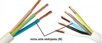
- A three-phase cable with a symmetrical load has the same voltage values on the cores, and the neutral wire current will tend to zero. This is true if the load is constant and purely active, which is impossible in real conditions;
- In networks, in addition to the active load, there is a reactive load in the form of transformer windings, reactors, etc. and as a result, inductive power appears in them;
- As a result, the resistance will consist of active, capacitive and inductive. It affects voltage losses in the network.
Current losses depend on the cable length. The longer it is, the greater the resistance, which means that the losses are greater. It follows that power losses in a cable depend on the length or length of the line.
Conclusion on choosing the wire cross-section for constant voltage:
The shorter and thicker the wire through which direct current flows, the lower the voltage drop across it, the better . That is, the voltage loss in the wires is minimal.
If you look at Table 2, you need to select the values from the top-right, without going into the “blue” zone.
For alternating current the situation is the same, but the issue is not so acute - there power is transferred by increasing the voltage and decreasing the current. See formula (1).
In conclusion, here is a table in which the DC voltage drop is set to a limit of 2%, and the supply voltage is 12 V. The required parameter is the maximum wire length.
Attention! This refers to a two-wire line, for example a cable containing 2 wires. That is, the case when, through a cable 1 m long, the current makes a path of 2 m, back and forth. I brought this option because... it is most often encountered in practice. For one wire, to find out the voltage drop across it, you need to multiply the number inside the table by 2. Thanks to attentive readers!
Table 3. Maximum wire length for 2% DC voltage drop.
| S,mm² I,A | 1 | 1,5 | 2,5 | 4 | 6 | 10 | 16 | 25 | 35 | 50 | 75 | 100 |
| 1 | 7 | 10,91 | 17,65 | 28,57 | 42,86 | 70,6 | 109,1 | 176,5 | 244,9 | – | – | – |
| 2 | 3,53 | 5,45 | 8,82 | 14,29 | 21,4 | 35,3 | 54,5 | 88,2 | 122,4 | 171,4 | – | – |
| 4 | 1,76 | 2,73 | 4,41 | 7,14 | 10,7 | 17,6 | 27,3 | 44,1 | 61,2 | 85,7 | 130,4 | – |
| 6 | 1,18 | 1,82 | 2,94 | 4,76 | 7,1 | 11,7 | 18,2 | 29,4 | 40,8 | 57,1 | 87 | 117,6 |
| 8 | 0,88 | 1,36 | 2,2 | 3,57 | 5,4 | 8,8 | 13,6 | 22 | 30,6 | 42,9 | 65,25 | 88,2 |
| 10 | 0,71 | 1 | 1,76 | 2,86 | 4,3 | 7,1 | 10,9 | 17,7 | 24,5 | 34,3 | 52,2 | 70,6 |
| 15 | – | 0,73 | 1,18 | 1,9 | 2,9 | 4,7 | 7,3 | 11,8 | 16,3 | 22,9 | 34,8 | 47,1 |
| 20 | – | – | 0,88 | 1,43 | 2,1 | 3,5 | 5,5 | 8,8 | 12,2 | 17,1 | 26,1 | 35,3 |
| 25 | – | – | – | 1,14 | 1,7 | 2,8 | 4,4 | 7,1 | 9,8 | 13,7 | 20,9 | 28,2 |
| 30 | – | – | – | – | 1,4 | 2,4 | 3,6 | 5,9 | 8,2 | 11,4 | 17,4 | 23,5 |
| 40 | – | – | – | – | – | 1,8 | 2,7 | 4,4 | 6,1 | 8,5 | 13 | 17,6 |
| 50 | – | – | – | – | – | – | 2,2 | 3,5 | 4,9 | 6,9 | 10,4 | 14,1 |
| 100 | – | – | – | – | – | – | – | 1,7 | 2,4 | 3,4 | 5,2 | 7,1 |
| 150 | – | – | – | – | – | – | – | – | – | 2,3 | 3,5 | 4,7 |
| 200 | – | – | – | – | – | – | – | – | – | – | 2,6 | 3,5 |
According to this table, our one and a half rack can only be 1 meter long. It will drop 2%, or 0.24V. We check using formula (4) - everything agrees.
If the voltage is higher (for example, 24 V DC), then the length can be correspondingly longer (2 times).
All of the above applies not only to constant voltage, but also to low voltage in general. And when choosing a cross-sectional area in such cases, one should be guided not only by the heating of the wire, but also by the voltage drop across it. For example, when powering halogen lamps through a step-down transformer.
Please comment on the article, how does theory coincide with practice?
Permissible voltage loss
Methods for arithmetic calculation of overhead electronic networks with wires made of various materials for voltage loss. The permissible voltage loss in an electronic network is determined by the likely permitted voltage deviations of potential users. Therefore, considerable interest has been given to the consideration of the request for an answer about voltage deviations.
For any receiver of electrical energy, specific voltage drops are possible. For example, non-simultaneous power units in standard standards allow voltage anomalies to be ±5%. This means, therefore, that in a curious incident, if the rated voltage of the provided electric motor is 380 V, from this voltage U'add = 1.05 Un = 380 x 1.05 = 399 V and U'add = 0.95 Un = 380 x 0.95 = 361 V should be based on its most likely permissible voltage indicators. Of course, all buffer voltages, included among the designations 361 and 399 V, will still satisfy the purchasing user and will compose a certain range, one or another, without variations, can be called the range of desired voltages.