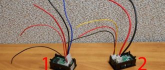
Dim light from lighting fixtures or the refusal of the washing machine to perform its functional duties indicates a possible drop in the supply voltage below normal. In such cases, it is necessary to measure the voltage, which will determine its compliance with the specified rating of the electrical network.
The same procedure is performed when repairing electronic devices, where the voltage drop on radio components and individual sections of the circuit is measured. This procedure is performed quite easily, but without understanding the physics of the process and the specifics of taking measurements, a person risks not only damaging expensive equipment, but also getting electrical injury, so next we will look at the basic principles of measurement.
Devices used
In every home, the electricity meter is in a state of constant measurement of alternating voltage, but it is extremely rare that this data is displayed anywhere. Some of them are connected directly, others through instrument transformers.
For practical purposes, the following can be used to measure voltage levels:
- Voltmeters;
- Multimeters
- Oscilloscopes.
A voltmeter is a device for testing potential differences. In practice, you can find both digital and analog voltmeters, in which the measured voltage is displayed on the display or by deflecting the arrow on the dial, respectively.
Important parameters when choosing both an electronic and a pointer voltmeter are units of measurement (mV, V, kV), operating range and accuracy class. However, the scope of their application is limited and is used, most often, for laboratory research, since for domestic and industrial needs it is impractical to maintain one device for measuring one electrical quantity.
A multimeter or digital tester is a more versatile device that can work with several parameters: electric current, resistance, frequency, temperature, voltage, etc. To measure voltage, the multimeter switches to voltmeter mode, the probes are connected to the appropriate connectors. Structurally, there are both digital and analogue models, in some of them you can switch the measurement range, select the type of current, in other multimeters all these values can be selected automatically.
An oscilloscope is a rather complex instrument for measuring potential differences, since it displays a curve of the measured value on a digital or analog display. In this case, you can stretch or shorten the frequency range to consider the shape of the pulse voltages, pulse duration, rises and dips in the function curve. Therefore, an oscilloscope for measuring voltage is used in electrical circuits and high-precision devices, in the manufacture and testing of radio components, etc. Few people keep an oscilloscope at home due to the high cost and complexity of operations.
3.5. ELECTRODYNAMIC SYSTEM
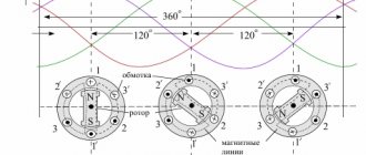
This system consists of two coils (Fig. 3.5.1), one of which is fixed and the other is movable. Both coils are connected to the network, and the interaction of their magnetic fields causes the moving coil to rotate relative to the stationary one.
From the equation it is clear that the scale of the electrodynamic system is quadratic. To eliminate this drawback, the geometric dimensions of the coils are selected in such a way as to obtain a scale close to uniform. These systems are most often used to measure power, i.e. as wattmeters, then:
In this case, the wattmeter scale is uniform. The main advantage of the device is its high measurement accuracy. Disadvantages include low overload capacity, low sensitivity to small signals, and a noticeable influence of external magnetic fields.
Network voltage measurement
In order to correctly measure voltage, it is necessary to clearly understand the principle and object of study. Therefore, it should be noted that voltage is an electrical quantity that shows the difference in charge between two electrical points. For example, if at one point the charge is +35 V, and at another +310 V, then the difference between these points will be 310 - 35 = 275 V, this will be the voltage. Accordingly, voltage measurements can only be made relative to something, so two points are used at once.
Rice. 1. Voltage measurement circuit
If we talk about the voltage drop at any object or section of the circuit, then the voltage measurement is carried out relative to the ends of the device or circuit, connection points, etc. It is important to take into account that a digital voltmeter or multimeter in measurement mode is considered to have infinite resistance or an open circuit.
A voltage drop is possible only if current flows, so connecting voltmeters in series with the object being measured is unacceptable, since current will stop flowing through it. An analogue or electronic voltmeter must only be connected in parallel with the signal being measured.
From a practical point of view, it should be noted that analog models of measuring instruments have an input impedance of 10 - 20 kOhm, and modern multimeters can boast 1 MOhm. Since leakage current may flow through the resistance at the input of the measuring device, this voltage divider will cause a decrease in measurement accuracy. Therefore, the closer the input resistance is to infinity, the more accurate the device you use.
It is important to note that measurements are taken under voltage, which poses a risk of electric shock. Therefore, it is important to take basic precautions. Next, we will consider the procedure for performing measurements for direct and alternating voltage.
Direct current
Rice. 2. DC voltage measurement
For a DC circuit, let's look at how to measure voltage using a digital multimeter. For this:
- Set the multimeter switch to constant voltage. On the panel it is indicated by the Latin letter V with the “=” sign, “+ and –” signs, and can also be denoted by the abbreviation DC.
- Select the desired measurement limit, which will be as close as possible to the expected nominal value, but higher than what is being measured.
- Install the probes into the appropriate connectors - black to the COM pin, red to the V pin.
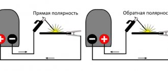
- Apply the multimeter probes to two points at once - red to positive, black to negative. If you do not know the position of the potentials in advance, and the device reading is negative, you just need to change the polarity of the connection.
On the display you will see the voltmeter readings; if the value is too low, switch the knob to a lower measurement range. When applying the probes, create a good force to avoid high contact resistance, otherwise they will introduce a noticeable measurement error.
Alternating current
Rice. 3. AC voltage measurement
In the AC circuit of a household circuit, it is important to take into account its danger due to the rating of 220/380 V. Therefore, if it is impossible to connect the multimeter directly during operation, its connection should be carried out with the voltage turned off using “crocodiles”.
Otherwise the measurement process is identical:
- Switch the multimeter handle to the AC voltage position. On the panel it is indicated as V with a “~” icon or the abbreviation AC.
- Use the handle to set the division to the desired limit based on the principle of the nearest higher potential relative to the measured value.
- Connect the probes to the corresponding pins: black to the COM pin, red to the V pin.
- Connect the measuring device to the desired device, note that the polarity of the probes does not matter here.
The display will show you the current value of the potential difference, which is the main value for all calculations. But, in addition to this, there is also an amplitude value that is √2 times or 1.41 times greater than the effective value.
LECTURE 11
15
LECTURE 11.
Measuring parameters of electrical circuit signals.
Methods for measuring voltage and current.
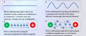
Current and voltage measurements are carried out in DC and AC circuits of a wide frequency range and pulse circuits.
In DC circuits the highest accuracy of measurements is, in AC circuits it decreases with increasing frequency; here, in addition to estimating the root-mean-square, average-rectified and maximum values, sometimes it is necessary to observe the shape of the signal under study and know the instantaneous values of current and voltage.
Current and voltage meters, regardless of their purpose, when turned on, must not disrupt the operating mode of the circuit of the object being measured; ensure a small measurement error, while eliminating the influence of external factors on the operation of the device, high measurement sensitivity at the optimal limit, quick readiness for operation and high reliability.
The choice of instruments that measure current and voltage is determined by a combination of many factors, the most important of which are:
- type of current being measured;
- approximate frequency range of the measured quantity and amplitude range;
- shape of the measured voltage (current) curve;
- power of the circuit in which the measurement is carried out;
power consumption of the device;
- possible measurement error.
Voltage measurement
carried out by methods of direct assessment and comparison.
If the required measurement accuracy, permissible power consumption and other requirements can be provided by ammeters and voltmeters of the electromechanical group, then this simple direct reading method should be preferred. In low-power DC and AC circuits, digital and analog electronic voltmeters are usually used to measure voltage. If it is necessary to measure voltage with higher accuracy, you should use instruments whose operation is based on comparison methods, in particular, on the contrast method.
Current measurement
possible direct - by direct assessment using analog and digital ammeters - and indirect. In this case, the voltage is measured across a resistor with a known resistance. Oscilloscopes are used to study the shape and determine the instantaneous values of voltage and current.
Voltage measurement in DC circuits.
Direct assessment method.
When using this method, a voltmeter is connected in parallel to the section of the circuit where the voltage needs to be measured. When measuring the voltage across the load R
in a circuit with an energy source whose EMF is
E
and internal resistance
R
0, the voltmeter is connected in parallel to the load (Fig. 11.1.).
If the internal resistance of the voltmeter R
V, then the relative voltage measurement error
,
where U
– the actual value of the voltage across the load
R
before turning on the voltmeter;
U
x – measured voltage value at load
R.
Resistance ratio R / R
V is inversely proportional to the ratio of the power consumption of the voltmeter
P
V to the power of the circuit
P
, therefore
.
To reduce the voltage measurement error, the power consumption of the voltmeter should be small and its internal resistance high ( R
V).
Voltage in DC circuits can be measured by any voltage meter operating on DC (analog magnetoelectric, electrodynamic, electromagnetic, electrostatic, analog and digital electronic voltmeters). The choice of a voltage meter is determined by the power of the measurement object and the required accuracy. The range of measured voltages ranges from microvolts to tens of kilovolts. If the object being measured is powerful, electromechanical voltmeters are used and the power consumption is not taken into account; if the measurement object is low-power, then the power consumption must be taken into account or electronic voltmeters must be used.
Comparison methods.
Compensation method (opposition method)
provides high measurement accuracy.
This is a method of comparison with a measure. Measuring instruments using the comparison method are called compensators
or
potentiometers
.
The principle of operation of the compensator is based on balancing (compensating) the measured voltage with a known voltage drop across a reference resistor. The moment of full compensation is recorded according to the readings of the null indicator.
A simplified circuit of a DC compensator is shown in Fig. 11.2. The circuit contains a source of exemplary emf E
0, standard resistor
R
0, auxiliary power source
E
vsp, variable resistor
R K
, adjusting rheostat
R
r and null indicator.
The null indicator is usually a galvanometer with a zero in the middle of the scale.
a measure of EMF), a normal element is used - a galvanic element manufactured using a special technology, the average value of the EMF at a temperature of 20 ° C is known with an accuracy of the fifth digit and is equal to E
n = 1.0186
V. A reference resistor is a specially designed resistance coil with a precisely known and stable resistance.
The voltage measurement process consists of two operations: establishing the operating current and balancing the measured voltage. To establish the operating current, switch P is set to position 1 and, by adjusting resistance R
p, achieve the absence of current in the galvanometer.
This will occur when the voltage drop across the resistor R0
becomes equal to the EMF of a normal element:
IR
0 =
E
0.
In this case, the operating current in the circuit R
r,
R
0,
R K I = E
vsp / (
R
r +
R
0+
R K
).
After setting the operating current, switch P is set to position 2 and, without changing the operating current, set the resistance value R K
=
R
x, at which the measured voltage
U
x will be balanced by the voltage drop
IR
x and there will be no current in the galvanometer circuit again. From here
E
0 /
R
0 =
U
x /
R
x and
U
x = (
R
x /
R
0)
E
0.
At constant values of E
0 and
R
0 the resistance scale
R K
can be graduated directly in units of DC voltage.
Since at the moment of equilibrium there is no current in the indicator circuit, we can assume that the input resistance R
the input of the compensator (from the side of the measured voltage) is equal to infinity, i.e.
Rin
= . This implies one of the main advantages of the compensator - the absence of power consumption from the measurement object.
Modern DC compensators are available in accuracy classes from 0.0005 to 0.2. The upper limit of measurement is up to 1 ... 2.5 V.
With sufficient sensitivity of the indicator, the lower limit of measurement can be several nanovolts.
Compensation methods are also used for AC measurements.
Differential method
is based on measuring the difference between the measured and known voltage with their incomplete compensation. The measurement scheme is shown in Fig. 11.3.
High resistance electronic voltmeter V
1 with a sensitive limit serves to measure the difference voltage between the measured
U
x and the known
U
voltage.
An analogue magnetoelectric or digital voltmeter V
2 is used to measure voltage
Uk
.
It is recommended that at Uk
=0, measure
the approximate value
Ux
V , and then set the
Uk
convenient for reading using V .
The measured voltage U
x with the indicated polarity of switching on the voltmeter
V
1 is defined as
U
x =
U
to +
U.
When measuring voltages in high-resistance circuits, the input resistance of magnetoelectric and electronic voltmeters may not be high enough. The differential measurement method allows you to increase the input resistance of the circuit to the required values, which are determined from the following formula:
.
The <, the >.
The differential method provides high accuracy of voltage measurement. The measurement error is determined mainly by the error of the voltmeter measuring U
To .
For measuring small DC voltages (about 10-8 V
) use galvanometric compensators.
DC current measurement.
Direct current measurement.
The ammeter is connected in series to the open circuit of the circuit under study.
Series connection of an ammeter with internal resistance R
A into a circuit with an EMF source
E
and resistance
R
(load and source resistance) leads to an increase in the total resistance and a decrease in the current flowing in the circuit.
The relative error I
of the current measurement
I x
is defined as
,
where I
– the actual value of the current in the circuit before the ammeter is turned on;
I x
is the measured value of the current in the circuit
R.
The resistance ratio can be replaced by the power ratio P
A and
P
consumption of the ammeter and the circuit itself, respectively:
I
= - (
RA
/
P
) / (1+
R
A /
P
).
The smaller the power consumption of the ammeter P
A compared to the power consumption of the circuit
P
in which the measurement is carried out.
Therefore, an ammeter connected in series to the measurement circuit must have low resistance, i.e. R
A0.
The range of values of direct currents, the measurement of which is encountered in various areas, is extremely large (from currents of 10-17 A
up to tens and hundreds of thousands of amperes). Therefore, naturally, the methods and means of measuring them are different.
Direct current measurement can be performed with any direct current meter: analog magnetoelectric, electrodynamic; analogue and digital electronic ammeters. If it is necessary to measure very small currents, significantly less than the total deviation current I
and a magnetoelectric meter, this meter is taken together with the UPT.
Currents 10-9–10-6 A
can be measured directly using highly sensitive magnetoelectric mirror galvanometers and galvanometric compensators.
Indirect current measurement.
In addition to direct current measurement with ammeters, it is possible to indirectly measure currents using resistors with a known resistance R
0, included in the open circuit, and highly sensitive voltage meters.
The measured current is defined as I x
=
U
0 /
R
0, where
U
0 is the voltage drop across the resistor
R
0, measured with a voltmeter or DC compensator.
To obtain minimal errors in current measurement, the resistance of the resistor R
0 must be much less than the resistance of the circuit in which the current is measured.
The indirect method is implemented in electronic analog and digital current meters.
Power frequency voltage and current measurement.
Measurement of power frequency voltage and current can be performed with any voltmeters and ammeters operating at a frequency of 50 Hz. When the object being measured is powerful, measurements are performed with electromagnetic and electrodynamic voltmeters and ammeters.
To measure power frequency voltages in circuits in which turning on a conventional direct evaluation device can disrupt the mode of this circuit due to power consumption and thereby distort the measurement results, AC compensators
.
To balance the measured voltage with a compensating voltage, the following conditions must be met: equality of voltages U x
and
U
k in absolute value;
the opposition of their phases ( x
- k = 180o); frequency equality; the same shape of the measured and compensating voltages. AC compensators are less accurate than DC compensators.
Current and voltage measurements in three-phase systems
.
In three-phase systems, current and voltage are measured with the same instruments as in single-phase systems. In a symmetrical three-phase system, a single ammeter or voltmeter can be used to monitor line currents and voltages. In unbalanced systems, a single voltmeter with a switch is often used to monitor line voltages.
When measuring line currents
in three-wire systems and to isolate devices from high-voltage sections of the circuit, a circuit with two current transformers is used (Fig. 11.4).
Fig. 11.4. Circuit diagram for connecting ammeters for measuring linear currents in three-phase
systems.
The use of such a circuit is possible due to the properties of three-phase systems, since. Therefore, the ammeter can be connected to line C without a current transformer. In this case, three ammeters are connected through two transformers. Similar prerequisites for measuring linear voltages [in this case] make it possible to use three voltmeters through two measuring voltage transformers to switch on (Fig. 11.5).
The use of these circuits for connecting devices is possible provided that transformers with the same parameters are used (including those with the same error signs). If this condition is not met, additional measurement errors arise. In both cases, the current and voltage values are determined by multiplying the instrument readings and the transformation ratio.
Fig. 11.5. Connection diagram of voltmeters for measuring linear
voltages in three-phase systems.
When measuring phase currents
in three-phase systems, three current transformers are used to convert currents and separate high and low voltage circuits. To connect voltmeters when measuring phase voltages in such systems, three voltage transformers are also used.
Power measurement methods.
Power measurement is carried out during the operation of various measuring and electrical equipment. The range of measured powers is 10-16 – 10+9 W in high-frequency DC and AC circuits.
Measurement methods differ significantly from each other depending on the parameters of the circuit in which the power is measured, the limit of power change and the frequency range.
Power measurement in DC circuits.
Power in DC circuits
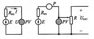
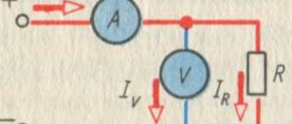
can be determined indirectly from the readings of a voltmeter and ammeter (Fig. 11.6).
With such a power measurement, a significant measurement error arises, since the errors of the devices are summed up and, in addition, an error arises due to the own power consumption of these devices.
Load power consumption P
= UI
.
Power P
x
,
calculated from instrument readings (Fig. 11.6, a),
P
x
= U
V
I
A
= U(I
V
+ I) = UI
V
+ UI = P
V
+ P
is greater than the actual value of the load power consumption by the power value P
V consumption of the voltmeter (
I
V
–
current in the voltmeter circuit). The greater the input resistance of the voltmeter, the smaller the error in determining the power in the load.
Power P
x
,
calculated from instrument readings (Fig. 11.6, b),
P
x
= U
V
I
A
= (U
A
+ U)I = U
A
I + UI = P
A
+ P
is greater than the actual value of power consumption of the load by the power value P
A consumption of the ammeter (
U
A
–
voltage drop across the ammeter). The lower the input resistance of the ammeter, the smaller the error in determining the power in the load. Therefore, the diagram shown in Fig. 11.6a is used to measure power at low load resistance, and the circuit shown in Fig. 11.6,b – at high resistances.
If the input resistances of the devices are known, then it is possible to make appropriate corrections to their readings and reduce the error in determining the power, i.e. get a more accurate measurement result.
Despite its apparent simplicity and accessibility, the ammeter and voltmeter method for measuring power P
in practice it is used extremely rarely.
This is explained by the fact that the named method requires simultaneous reading of the readings of two instruments and subsequent calculation
of P.
The most simple way and with the required accuracy is to measure power directly using one single-element electrodynamic wattmeter
.
The inclusion of such a wattmeter in a direct current circuit must be carried out in compliance with the correct connection of the generator terminals of the winding of the current and voltage circuits. Figure 11.7 shows the inclusion of a wattmeter
PW to
measure power
P.
The generator terminal of the current winding of the wattmeter is always turned on towards the power source. The generator terminal of the voltage winding, in order to reduce the methodological error, can be turned on as shown in Fig. 11.7, a or b.
The circuit in Fig. 11.7a is used with a relatively large value of load resistance R
naked, and the diagram in Fig. 11.7, b - at a relatively low value of load resistance
R
naked. (The load resistance is commensurate with the resistance of the current circuit. The value of the resistance of the current circuit is always indicated on the dial of the device).
In most cases where wattmeters are used, the load resistance R
is relatively large (the value of the load resistance is much greater than the resistance of the series current circuit of the wattmeter) and, therefore, the wattmeter must be turned on according to the circuit in Fig. 11.5, a.
It is quite obvious that failure to correctly turn on the generator terminal of any of the wattmeter windings leads to a change in the direction of the torque and the wattmeter indicator going off the scale.
Measurement of active power in alternating current circuits.
Active power in a single-phase circuit is measured using single-element wattmeters. Extension of measurement ranges in alternating current circuits is carried out using current and voltage measuring transformers.
Power measurement using the one-device method.
When using the single instrument method, power is measured using a single-element wattmeter. The method is used when measuring power in single-phase circuits and symmetrical three-phase circuits (the complex resistances of the phases are the same). In both cases, the voltage winding of the wattmeter is connected to the phase voltage, and the current winding is connected to the cut of the wire of any phase. In Fig. Figure 11.8 shows the connection of a single-element wattmeter to a single-phase alternating current circuit. Neglecting the methodological error, we record the wattmeter readings:
P PW
= UI cos ,
where U
and
I
– effective values of voltage and load current
; =
(
U , I
).
The wattmeter reading in this case will correspond to the power of one phase. To obtain the power of the entire three-phase circuit, it is necessary to triple the wattmeter reading, i.e. P
= 3 P PW
.
Switching on the fixed coil of a wattmeter in series with the load is possible only at load currents of 10-20 A
.
At high load currents, the fixed coil of the wattmeter is connected through a current transformer ( TA
).
When measuring in high voltage circuits (over 600 V
), the moving coil of the wattmeter is not connected directly to the measuring circuit, but through a voltage transformer (
Т V
), and the fixed coil of the wattmeter is connected through
TA
(regardless of the value of the load current).
The value of the measured power is determined by the wattmeter reading multiplied by the product of the transformation coefficients T V
and
TA
:
R
x =
Р Р W K U
nom
K I
nom,
where P
x – measured value of active power in the load circuit;
Р Р W
– wattmeter reading;
K U
nom,
K I
nom – nominal transformation ratios, respectively,
T V
and
TA
.
The measured power value will differ from the actual value
errors in the transmission of voltage and current values, as well as angular errors of transformers. Electrodynamic wattmeters are manufactured with multi-range, high accuracy classes (0.1; 0.2) with a range of measured powers from tenths of W
up to 3 – 6
kW
. For rough measurements, ferrodynamic wattmeters are used as panel devices.
It should be noted that active power measurement with single-element wattmeters is carried out only in laboratory practice. For technical measurements in industrial conditions, two-element wattmeters are used to measure active power in three-phase three-wire circuits, and three-element wattmeters in four-wire circuits.
In addition to electrodynamic wattmeters, electronic rectifier, thermoelectric, digital and other wattmeters are used to measure power.
Power measurement using the two-instrument method.
The two-instrument method is used to measure power in a three-phase, three-wire network using two single-element wattmeters. The method gives correct results regardless of the connection diagram and the nature of the load, both with symmetry and asymmetry of currents and voltages. In addition, the two-instrument method is used to include the elements of a two-element wattmeter when measuring its power in a three-phase three-wire network
In Fig. Figure 11.9 shows a circuit diagram for connecting two single-element wattmeters. Usually the current winding of one wattmeter, for example, PW 1,
is switched on in phase
A
, and the current winding of another wattmeter -
PW 2 -
in
phase C. The voltage windings of the wattmeters are connected to linear voltages as shown in Fig. 11.9. When measuring power using the two-instrument method, the total power of the circuit is equal to the algebraic sum of the wattmeter readings
P
= P W 1 + P W 2 ,
where P W 1 = U A B I A
cos 1
;
P W 2 = U C B I C cos 2 ,
(
1 –
phase shift between vectors
U A B
and
I A ; 2 –
phase shift between vectors
U C B
and
I C
). Or
P W 1
= U
L
I
L
cos
(30o-);
P W 2
= U
L
I
L
cos
(30o+),
where
is
the phase shift between voltage and current in phase.
The power of any 3-phase system is calculated by the formula:
Thus, the sum of the wattmeter readings PW 1
and
PW 2
is nothing more than the power of a three-phase circuit.
Power measurement using the three-instrument method.
The three-instrument method is used when measuring power in a three-phase, four-wire circuit (using three single-element wattmeters connected to each phase). Just like the two-device method, the three-device method gives correct results regardless of the connection diagram and the nature of the load, both with symmetry and asymmetry of currents and voltages. According to the circuit that implements the method of three devices, elements of three-element three-phase wattmeters are also included. Obviously, to find the power of a 3-phase four-wire circuit, it is necessary to take the algebraic sum of all wattmeters:
.
Real voltage measurement examples
The simplest example of measuring voltage at home is a AA battery. In it you need to attach the black probe to the “–” terminal and the red one to the “+” terminal, set the switch position to 2 V DC voltage.
Rice. 4. Example of measuring voltage on a battery
If the readings for a 1.5 V battery are in the range from 1.6 to 1.2 V, then such a power source is considered suitable for all equipment; if the values reduce to 1 - 0.7 V, pulsed devices will be started from the battery, for example, a watch. If the voltmeter shows 0.6 V or less, the discharge has reached a critical value.
When measuring the potential difference in a household network, you should touch the contacts of the socket with the probes. Since the insulated part of the probe has a restrictive ring behind which there is a long rod, you can safely reach into the outlet without the risk of touching live parts. Deviations from the nominal value by 10% are considered acceptable, that is, from 198 to 142 V.
You can also measure the potential difference at the output of a car battery or at another element of the electrical wiring circuit. To do this, the black probe of the multimeter is installed on the “–” terminal of the battery, and the red one on the “+” terminal.
If the battery is charged, then the voltmeter readings should be in the range from 12 to 14 V, but there are models with a large spread. This measurement allows you to diagnose various causes of problems.
3.8. POWER MEASUREMENT
To measure DC power, simply measure voltage and current. The result is determined by the formula:
The ammeter and voltmeter method is also suitable for measuring total power, as well as active power of alternating current, if cosj = 1. Most often, power measurement is carried out by one device - a wattmeter. As mentioned earlier, the electrodynamic system is the best for measuring power. The wattmeter is equipped with two measuring elements in the form of two coils: serial and parallel. The first coil carries a current proportional to the load, and the second coil flows proportional to the network voltage. The angle of rotation of the moving part of the electrodynamic wattmeter is proportional to the product of current and voltage in the measuring coils:
In Fig. 3.8.1 shows a diagram of connecting a wattmeter to a single-phase network.
In three-phase networks, one, two and three wattmeters are used to measure power. If the load is symmetrical and connected as a star, then one wattmeter is sufficient (Fig. 3.8.2, a). If in the same circuit the load is asymmetrical in phases, then three wattmeters are used (Fig. 3.8.2, b). In the “triangle” connection of consumers, power is measured with two wattmeters (Fig. 3.8.2, c).
3.9. RESISTANCE MEASUREMENT
Electrical resistance in DC circuits can be determined indirectly using a voltmeter and ammeter. In this case:
You can use an ohmmeter - a direct reading device. There are two ohmmeter circuits: a) serial; b) parallel (Fig. 3.9.1).
The scale equation of the sequential pattern of intention is:
where r is the resistance of the galvanometer circuit. When the angle of rotation of the moving part of the device is determined by the value of the measured resistance Rx. Therefore, the instrument scale can be directly calibrated in Ohms. Key K is used to set the instrument needle to the zero position. Parallel type ohmmeters are more convenient to use for measuring small resistances. Resistance measurements can also be carried out with ratiometers. In Fig. 3.9.2 shows a schematic diagram of the ratiometer.
For this scheme we have:
Deviation of the moving part of the ratiometer:
Thus, the reading of the device does not depend on the voltage of the power source and is determined by the value of the measured resistance Rx.