What is a triac and what does it look like - briefly
The phrase “symmetrical triode thyristor” is translated into English as symmetrical triode thyristor. It is also called triode for alternation current (triode for alternating current). Or abbreviated as triac.
All these names are generally accepted; they are found in the technical literature. You may encounter any of them.
I show photographs of the most typical housing designs with which these semiconductor devices are produced.
The photo of any of them clearly shows three contact pins. They, together with the housing structure, are manufactured for the rated load power, which must be transmitted and switched in switch mode.
What is a key in electronics and electrics - a figurative explanation
Let's compare its operation with the design of a locked front door.
A person without a key will not be able to get through it: the lock is securely closed. The owner of the apartment and his trusted people have a key, open the door, and freely enter the premises.
Electrical keys work in exactly the same way, passing the load. Only they are controlled by command and come in three types:
- Mechanical.
- Electromechanical.
- Electronic.
Electric current does work, for example, it illuminates a room. And the key allows a person to control this process through the use of certain technologies. They allow you to switch power contacts and even perform additional actions.
Table: how an electric key works
| Functions | Key type | ||
| Mechanical | Electromechanical | Electronic | |
| How does it work | The power contacts of the switch, switch, button are switched by a kinematic circuit due to manipulation by the operator | The power contacts are switched by an electromagnet under the influence of a control signal. | The power contacts are switched by an electronic circuit under the influence of a control signal. |
| Control signal | Manual action | The operation of the electromagnet occurs under the influence of a certain electrical parameter of a standardized value (set point). It can be current, voltage, frequency, power, phase... | The bipolar transistor is switched by the input control voltage. A field-effect transistor is an electric field, which is why it is called that. Thyristor and triac operate from current flowing through the control electrode. |
| Main advantage | Relative simplicity of the mechanism | Possibility of remote switching by changing various electrical signals | In addition to remote switching of the circuit, there is an adjustment of the output current, which allows you to assemble various regulators. As an example, change the load power, set the rotation speed of the electric motor. |
The main disadvantage of mechanical and electromagnetic switches is the switching of power contacts, which forcefully breaks the load circuit.
In this case, an electric arc occurs, burning the surface of the contacting metals.
It can also cause a fire or explosion of flammable media.
A mandatory procedure has been introduced at energy enterprises: annual internal inspection of all relays, contactors and starters, including cleaning of contact surfaces and tightening of contact connections.
Electronic keys work without an arc. They have reduced dimensions and fit well inside the housings of electrical appliances.
A variety of BTA triacs
There are also triacs for 12, 41 amperes. They can withstand heavy loads. I have a homemade power regulator using a VTA triac. You can order a power regulator on a triac here. On my channel for visiting radio amateurs, the videos cover reviews of electrical circuits, power supplies, amplifiers, voltage and current converters, various circuits and construction kits made from radio components. Which are assembled at home and are available to every amateur without any problems or difficulties. Order and use for your own purposes to control household appliances.
I installed a larger radiator on my power (voltage) regulator and now it can withstand heavy loads. That's all, subscribe to the channel and leave your comments on what and how you would do with this module.
Subscribe to my channel, I will be glad to have new subscribers, like and comment.
Also watch the video voltage regulator
To Home Page.
How a triac is controlled: basic principles
Electronic elements (diodes, transistors, thyristors, triacs) are created for various tasks and have different numbers of semiconductor layers. The method of mastering information from simple to complex will help us understand the principles of triac control.
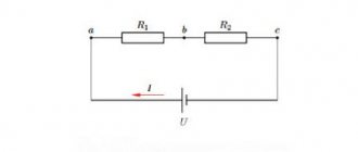
I have already described the basics of current flow in semiconductors earlier. In a diode consisting of two “p” and “n” junctions, the charge carriers are holes and electrons.
When a voltage source is connected directly to a load, a current is generated, and when connected in reverse, it stops. This process is clearly described by the current-voltage characteristic (shown on the right).
This algorithm is based on the operation of one pn junction. As the design of elements becomes more complex, their number gradually increases.
Transistor connection circuit: 2 types of designs
First, let me clarify the capabilities of bipolar models.
How does a bipolar transistor work?
Two semiconductor junctions are involved in the operation of this switch. A bipolar transistor is created with one of two possible structures:
- pnp;
- or npn.
I will briefly give an example of the device and operation of the first option.
The right side of the picture shows the characteristics of the dependence of currents through the emitter and collector on the applied voltage in the emitter-base and collector-base sections of the circuit.
The state of semiconductor junctions changes by the voltage applied to them, which achieves one of four modes:
- main or active (collector junction open);
- inverse (emitter junction open);
- saturated (both transitions are open);
- cutoff (both transitions are closed).
During operation, mainly the last two modes are used by changing the current through the base. Its termination closes the current through the load connected to the collector, and the supply with a nominal value opens it, that is, it puts it into saturation mode.
Designs with npn junctions work on the same principles, but their current directions change.
How does a field-effect (unipolar) transistor work?
Let's look at the example of an n-channel pnp structure. For our case this is quite enough.
The channel width and current Ic through the drain and source increases when a positive voltage is introduced to the gate (Uzi). It can reach a certain threshold value at which the transistor closes.
The output current-voltage characteristic depends on the voltage between drain and source (Uс).
The FET switch works by altering its conductivity by the voltage applied to the gate when it goes into open or close mode.
Such circuits are characterized by increased performance even in relation to bipolar modules.
Thyristor connection diagram: 2 connection options for DC and AC circuits
I have already devoted a separate article to this topic on my blog. Here I briefly show that in its structure there are no longer three, but four semiconductor junctions, for example, pnpn.
Such a circuit can be simplified to be represented as consisting of two identical transistors (2 transistor switches connected back to back with the base of one switched to the collector of the other).
The current-voltage characteristic of the thyristor has two bias regions and 4 modes, of which we are only interested in two:
- open (1-2);
- or closed state (0-1).
They are in the first quadrant. Look closely at this area. It will be useful to us in understanding the operation of the triac.
Using one thyristor allows you to control one half-wave of a sinusoidal signal or DC circuits.
How thyristors are connected to control the load in a 220 volt household network
Let's take the previous circuit as a basis and additionally include another thyristor with its own control circuit. This will result in full-wave rectification at load R.
It is also produced on triac.
Triac connection circuit: how a unique current-voltage characteristic is created
In principle, a triac (symmetrical controlled diode) can be imagined as consisting of thyristors assembled in back-to-back parallel. That is why it is designated as such on electrical diagrams.
Pay attention to its anode and cathode electrodes (+ and -). They were renamed T1 and T2. There are other designations. This is due to the fact that triac is capable of simultaneously transmitting both semiharmonics of the positive and negative directions of a variable sine wave.
In other words: the triac works with both the forward and reverse direction of current.
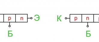
The structure of its semiconductor layers can be represented as follows.
And their current-voltage characteristic in the first quadrant works like that of a thyristor (forward currents), and in the third it is symmetrically inverted (reverse direction), which once again demonstrates the principle of operation of triac.
Such a semiconductor differs in operation:
- high reliability, providing it with a long service life;
- the absence of moving contact mechanisms that create interference in the network;
- acceptable cost.
It should be taken into account that he:
- requires heat removal (use of additional cooling radiators), because it can burn out if overheated;
- is exposed to high-frequency interference from the electrical network - an RC circuit that shunts electrical noise is built into the circuit.
The technical capabilities of the triac make it possible to create on its basis not only electrical switches that switch various circuits, but also all kinds of regulators:
- power;
- changes in lamp brightness;
- speed of electric motors.
Power regulator circuit
You can connect different devices to this power (voltage) regulator, up to 2000 watts. (but subject to replacing the radiator with a larger one), such as a lamp, a soldering iron for heating control, a drill and other devices where you need to regulate lighting, voltage, speed, temperature. To do this, as I wrote above, you need to smoothly turn the variable (tuning) resistor R2 towards increasing or decreasing the load.
The diagram shows:
Triac BTA16-600B on the radiator, Dinistor DIAC DB3, Capacitor C1 – 0.1 uF 400 V, Variable resistors R1 – 500 K, R2 – multi-turn resistor 2 Mohm R3 – 0.25 watt – 4.7 kOhm, R 4 – 1W -100 Ohm Connection terminals power and load.
What should be noted is that such a power (voltage) regulator is sold with small radiators and there is no paste between the triac and the radiator. When connecting a large load, more than 500 watts, it is better to install a larger radiator and, of course, with paste. The regulator works properly, smoothly reduces and increases the load. In general, it is quite suitable for home purposes. The only thing is that you can strengthen it if you install a higher current triac and a radiator. You can also install resistors of higher power; capacitors will do just fine according to the diagram.
Main parameters: VRRM,V (Peak repeating reverse voltage) 600 IT(RMS) (max.),A (On-state operating current) 16 VDRM (max.),V (Peak repeating on-state voltage) 600 IFSM (max .),A (Peak peak forward current per diode at a temperature of 10 ms) 168 IFT (max.),mA (Minimum gate current) 50 dV/dt,V/µs (Critical rate of rise of voltage in the off state)1000 dI/dt ,A/ms (Critical rate of rise of current in open position) 14 TA,°C (Operating temperature range) from -40 to 125 Case TO-220AB
Using a tester
Checking the functionality of a triac with a multimeter or tester is based on knowledge of the operating principle of this device. Of course, it will not give a complete picture of the condition of the part, since it is impossible to determine the performance characteristics of the triac without assembling the electrical circuit and taking additional measurements. But often it will be enough to confirm or refute the functionality of the semiconductor junction and its control.
To check the part, you need to use a multimeter in resistance measurement mode, that is, as an ohmmeter. The contacts of the multimeter are connected to the working contacts of the triac, and the resistance value should tend to infinity, that is, be very large.
After this, the anode is connected to the control electrode. The triac should open and the resistance should drop to almost zero. If this is what happened, most likely the triac is operational.
When the contact with the control electrode is broken, the triac should remain open, but the parameters of the multimeter may not be enough to provide the so-called holding current, at which the device remains conductive.
The device can be considered faulty in two cases. If, before voltage appears at the contact of the control electrode, the resistance of the triac is negligible. And the second case, if when voltage appears at the contact of the control electrode, the resistance of the device does not decrease.