- Technical support
- Articles
- Installation technology for water heated floors
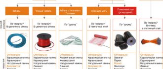
#warm floor #built-in heating #design #installation #adjustment
The most common way to implement underfloor heating systems is monolithic concrete floors, made by the so-called “wet” method. The floor structure is a “layer cake” made of various materials (Fig. 1).
Fig. 1 Laying underfloor heating loops with a single coil
Installation of a heated floor system begins with preparing the surface for installation of a heated floor. The surface must be level, unevenness in area should not exceed ±5 mm. Irregularities and protrusions of no more than 10 mm are allowed. If necessary, the surface is leveled with an additional screed. Failure to comply with this requirement may lead to air-filling of the pipes. If there is high humidity in the room below, it is advisable to install waterproofing (polyethylene film).
After leveling the surface, it is necessary to lay a damper tape at least 5 mm wide along the side walls to compensate for the thermal expansion of the heated floor monolith. It must be laid along all walls framing the room, racks, door frames, bends, etc. The tape should protrude above the planned height of the floor structure by at least 20 mm.
After which a layer of thermal insulation is laid to prevent heat leakage into the lower rooms. It is recommended to use foam materials (polystyrene, polyethylene, etc.) with a density of at least 25 kg/m3 as thermal insulation. If it is impossible to lay thick layers of thermal insulation, then in this case foil thermal insulation materials with a thickness of 5 or 10 mm are used. It is important that foil thermal insulation materials have a protective film on the aluminum. Otherwise, the alkaline environment of the concrete screed destroys the foil layer within 3–5 weeks.
Pipe layout
It is carried out with a certain step and in the required configuration. It is recommended that the supply pipeline should be laid closer to the outer walls.
When laying a “single coil” (Fig. 2), the temperature distribution of the floor surface is not uniform.
Fig.2 Laying underfloor heating loops with a single coil
When laying spirally (Fig. 3), pipes with opposite flow directions alternate, with the hottest section of the pipe adjacent to the coldest. This leads to an even temperature distribution over the floor surface.
Fig.3 Laying heated floor loops in a spiral.
The pipe is laid according to the markings applied to the heat insulator, with anchor brackets every 0.3 - 0.5 m, or between special protrusions of the heat insulator. The laying step is calculated and ranges from 10 to 30 cm, but should not exceed 30 cm, otherwise uneven heating of the floor surface will occur with the appearance of warm and cold stripes. Areas near the exterior walls of a building are called boundary zones. Here it is recommended to reduce the pipe laying pitch in order to compensate for heat loss through the walls. The length of one circuit (loop) of a heated floor should not exceed 100–120 m, the pressure loss per loop (including fittings) should not exceed 20 kPa; the minimum speed of water movement is 0.2 m/s (to avoid the formation of air pockets in the system).
After laying out the loops, immediately before pouring the screed, the system is pressure tested at a pressure of 1.5 of the working pressure, but not less than 0.3 MPa.
When pouring a cement-sand screed, the pipe should be under a water pressure of 0.3 MPa at room temperature. The minimum pouring height above the pipe surface must be at least 3 cm (the maximum recommended height, according to European standards, is 7 cm). The cement-sand mixture must be at least grade 400 with a plasticizer. After pouring, it is recommended to “vibrate” the screed. When the length of a monolithic slab is more than 8 m or the area is more than 40 m2, it is necessary to provide seams between the slabs with a minimum thickness of 5 mm to compensate for the thermal expansion of the monolith. When pipes pass through seams, they must have a protective sheath of at least 1 m in length.
The system is started only after the concrete has completely dried (approximately 4 days per 1 cm of screed thickness). The water temperature when starting the system should be room temperature. After starting the system, increase the supply water temperature daily by 5°C to operating temperature.
Laying schemes
There are several types of pipe heat distribution schemes. Each of them is used in different cases.
Before reading the diagrams, it is important to understand what a “laying step” is. It assumes the distance between the pipes.
It is often made the same. But, if there is a place in the room that needs to be heated more intensely, a smaller step is taken in this place, this causes the pipes to be located closer to each other and warmer.
Snake
The snake is the easiest to install. More often used in small, cozy rooms. The heat transfer of the snake is lower than other options. The classic snake pitch is 150 mm (100 mm at the wall and cold zone).
Below, in this diagram (on the left), you can see that the pipes heat up only on one side (by half), the other part begins to cool, and by the end of the snake the water has completely cooled down. This is the main disadvantage of such a system. But, it is ideal in rooms where one part of the room needs to be warmed up, and it is desirable to leave the second part cool or less warm.
The problem of uneven heating can be corrected by using a double snake circuit. Its diagram is shown below (right).
There is also an angular snake. It is used if the walls extending from both sides of the corner face the street. These walls cool down during the cold period, so it is recommended to install a corner option along these walls. Moreover, the heating part of the snake will pass right next to these walls. The closer to the center of the room, the less heating.
Watch a video in which a heated floor installer lays the coolant in a “snake” pattern. At the end, the video briefly describes how to connect the snake to the pump and distributor.
Do-it-yourself water heated floor. Part 2. Pipe installation
Snail
This type of floor is a spiral, hence the name “Snail”. Compared to a snake, it is more efficient in heating the room. Heat is distributed evenly.
Laying starts from the edge of the room, runs along the walls and reaches the center, then turns around and continues from the center to the edge. The step for this installation is from 1 cm. Most often, a step of 2-3 cm is used.
If the room is large, you should not stretch the cochlea, as heating the room will be ineffective. It is better to divide the snail into 3 different circuits, as shown in the figure below:
A more visual montage of the snail is shown in the video. The master lays the pipes step by step. Gives useful tips that make floor installation easier. Several snails are used per room for better heating of the room.
Water Heated Floor, installation
Combined layout scheme
When installing a heated floor in this way, a snake and a snail are used together. For example, given a room of 4 rooms. The largest of them will be a snail. The smaller ones are like a snake.
You can make 2 turns of the snake in one of the rooms, and then continue with the snail. Those. There is a combination of schemes in 1 room.
Below is a diagram of the combined installation:
This method is recommended to be used only by experienced specialists, and not just for “diversity”. It is important to correctly calculate the distribution of heat throughout the room and rooms, to think about where the cold zones should be (places where furniture will be placed). If the combination is not necessary, then it is not used.
We invite you to watch a useful video. The master in the diagram shows the principle of laying a combined floor system (snake + snail). For example, a room of 4 separate rooms (kitchen, bedroom, etc.) is used.
3 How to make a layout diagram for a heated floor contour
Basic temperature requirements for underfloor heating systems
- It is recommended to take the average temperature of the floor surface no higher (according to SNiP 41-01-2003, clause 6.5.12):
- 26°C for rooms with constant occupancy
- 31°C for rooms with temporary occupancy and bypass paths of swimming pools
- The temperature of the floor surface along the axis of the heating element in children's institutions, residential buildings and swimming pools should not exceed 35°C
According to SP 41-102-98, the temperature difference in certain areas of the floor should not exceed 10°C (optimally 5°C). The coolant temperature in the underfloor heating system should not exceed 55°C (SP 41-102-98 clause 3.5 a).
TOP 3 popular manufacturers of electric heated floors
| Photo | Name | Rating | Price | |
| #1 | Devi | ⭐ 97 / 100 | More details | |
| #2 | Rehau | ⭐ 95 / 100 | More details | |
| #3 | Caleo | ⭐ 94 / 100 | More details |
Caleo
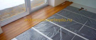
Caleo film infrared heated floor is designed for quick installation of a “warm floor” heating system using the “dry installation” method, without screed and dust. Ideal for cosmetic repairs under laminate, carpet, linoleum and parquet boards.
Caleo
pros
- high quality;
- excellent heat dissipation;
- The kit includes everything necessary for installation;
- Installation and assembly instructions included.
Minuses
- increased film fragility.
warm floor caleo
Rehau
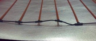
Rehau electric underfloor heating is a system of two-core self-regulating cables of a fixed length with increased resistance. On the outside they are covered with a double layer of insulation and protective braiding.
Rehau
pros
- excellent quality;
- installation under any covering;
- optimal heat distribution.
Minuses
- relatively high cost.
rehau solelec
Devi
Devi electric heated floors are manufactured in Denmark. The company's products are distinguished by high quality, affordable price and versatility. All components of this brand are suitable for any type of heated floors produced by this manufacturer.
Devi
pros
- simple installation;
- does not dry out the air;
- manufacturer's warranty;
- service life more than 20 years.
Minuses
- high energy consumption.
heated floor devi
Set of water heated floors for 15 m2
Heated floor kit for heating rooms with an area of 15-20 m2 with a mixing unit with manual adjustment of the coolant temperature based on the mixing and separating valve MIX 03. The operating temperature of the coolant is adjusted manually by turning the valve handle.
When laying a heated floor loop in a spiral (screed thickness 3 cm with ceramic tile flooring) in increments of 15-20 cm and an estimated coolant temperature of 30°C - floor surface temperature 24-26°C, coolant flow rate of about 0.2 m3/h , flow speed 0.2-0.5 m/s, pressure loss in the loop approximately 5 kPa (0.5 m).
Accurate calculations of thermal and hydraulic parameters can be carried out using the free underfloor heating calculation program Valtec Prog.
| Name | vendor code | Qty. | Price |
| MP pipe Valtec | V1620 | 100 m | 3 580 |
| Plasticizer | THZ.P.10 | 2x10 l | 1 611 |
| Damper tape | THZ.LD.100.01.25 | 2x10 m | 1 316 |
| Thermal insulation | VT.HS.FP.0312 | 18 m2 | 2 648 |
| Three way mixing valve | VT.MIX03.G.05 ¾” | 1 | 1 400 |
| Circulation pump | UPC 25-40 | 1 | 2 715 |
| Nipple adapter | VT 580 1”x3/4” | 1 | 56.6 |
| Nipple adapter | VT 580 1”x1/2” | 1 | 56.6 |
| Ball valve | VT 218 ½” | 1 | 93.4 |
| Straight connector with transition to internal thread | VTm 302 16x ½” | 2 | 135.4 |
| Ball valve | VT 219 ½” | 1 | 93.4 |
| Tee | VT 130 ½” | 1 | 63.0 |
| Barrel | VT 652 ½”x60 | 1 | 63.0 |
| H-B adapter | VT 581 ¾”x ½” | 1 | 30.1 |
| Total | 13 861.5 |
Installation diagram of a warm water floor on a concrete base
Scheme of a water heated floor on a concrete base
Installation of water heated floors with concrete screed
Installing water heating on a concrete base contains several “layers of the cake”.
Set of water heated floors up to 30 m2 - 1
Heated floor kit for heating rooms with an area of 30-40 m2 with a mixing unit with manual adjustment of the coolant temperature based on the mixing and separating valve MIX 03. The operating temperature of the coolant is adjusted manually by turning the valve handle. To ensure equal coolant flow in the heated floor loops, their length and laying pattern must be the same.
When laying a heated floor loop in a spiral (screed thickness 3 cm with ceramic tile flooring) in increments of 15-20 cm and an estimated coolant temperature of 30°C - floor surface temperature 24-26°C, coolant flow rate of about 0.2 m3/h , flow speed 0.2-0.5 m/s, pressure loss in the loop approximately 5 kPa (0.5 m).
Accurate calculations of thermal and hydraulic parameters can be carried out using the free underfloor heating calculation program Valtec Prog.
| Name | vendor code | Qty. | Price |
| MP pipe Valtec | V1620 | 200 m | 7 160 |
| Plasticizer | THZ.P.10 | 4x10 l | 3 222 |
| Damper tape | THZ.LD.100.01.25 | 3x10 m | 1 974 |
| Thermal insulation | VT.HS.FP.0312 | 2x18 m2 | 5 296 |
| Three way mixing valve | VT.MIX03.G.05 ¾” | 1 | 1 400 |
| Nipple adapter | VT 580 1”x3/4” | 2 | 113.2 |
| Nipple | VT 582 3/4” | 1 | 30.8 |
| Tee | VT 130 ¾” | 1 | 96.7 |
| Square | VT 93 ¾” | 1 | 104.9 |
| Direct drive | VT 341 ¾” | 1 | 104.9 |
| Circulation pump | UPC 25-40 | 1 | 2 715 |
| Ball valve | VT 217 ¾” | 2 | 266.4 |
| Collector | VT 500n 2 outlets x ¾” x ½” | 2 | 320 |
| Cork | VT 583 ¾” | 2 | 61.6 |
| Fitting for MP pipe | VT 710 16(2.0) | 4 | 247.6 |
| Fitting for MP pipe | VTm 301 20 x ¾” | 1 | 92.4 |
| Fitting for MP pipe | VTm 302 20 x ¾” | 1 | 101.0 |
| Total | 23 306.5 |
Features of the device and connection of the cable floor
Types of electric heated floors
Electric floors can be installed from infrared film or rod mats, but we will pay attention to the cable option, which is mounted under the screed. This is a modern and very reliable solution that allows you to organize heated floors not only in a private house, but also in an apartment, as well as heat rooms where there is no water, but there is electricity.
- The installation technology of such a floor is much simpler than a water pipe floor. The main thing here is to correctly connect the wires to the thermostat. The basic element of this system is the heating cable, and when purchasing it, you should find out its power per unit length. It is important that this figure does not exceed 21 W/m and is not less than 17 W/m.
Installing a cable floor is easier than installing a water floor
- To install heated floors, you can use a self-regulating cable. But it has one drawback. The level of heat it generates depends on the ambient temperature, and if the floor is covered with carpet or furniture, or tiled with ceramic tiles, the floor will cool itself.
- Therefore, in such systems, resistive cable is often used as the most optimal option, suitable for all types of coatings. It can be single-core or double-core, up to 3 and 5 mm thick, respectively. This cable is easier to install, but costs more. Wires of minimal thickness (2-3 mm) are laid under a dry screed, and thick ones are poured in a monolithic manner.
Cable heated floor
The second most important element, with the help of which, in fact, the entire system is controlled, is a thermostatic device . Its cost is the lion's share of the price of the floor, but you can't live without it. The only way to save money is by purchasing a model with a minimum set of options. And there are many options, there are wireless, touch, and push-button.
Thermostat for heated floors
You will still have to select a thermostat yourself, since it is not included in the floor kit.
Cable installation
The cable installation work is quite simple. For clarity, we present the instructions in the form of a table with pictures and comments.
Cable heated floor Electrolux Twin Cable
Table. Step-by-step installation instructions.
| Steps, photo | Description of work |
| Step 1. Calculation of the area of the heated floor | The amount of cable required to heat a room is calculated minus the area occupied by stationary furniture. The maximum power of a two-core cable is 2500 kW, and if more is required, then several cable sections are laid. |
| Step 2. Preparatory work related to installing the thermostat | First, a place is prepared for installing the regulator. It can be anything - the main thing is that it is no closer than 30 cm to the floor and does not interfere with the arrangement of furniture. If the floor is installed in a room with high humidity (bathroom, sauna), it is better to place the thermostat on the outside of the wall. |
| Step 3. Drilling a recess for the regulator box | Next, using a drill with a socket attachment, drill a hole for the thermostat housing. |
| Step 4. Cutting the grooves for the wire | A grinder is used to cut a groove with a cross-section of 20*20 mm for laying the wire. |
| Step 5. Cleaning the room | After preparing the wall for installing the thermostat, you should start preparing the floor for laying the cable. You start with cleaning. |
| Step 6: Prime the subfloor | If the base of the floor is concrete, it needs to be primed so that it does not collect dust. |
| Step 7. Laying insulation | Let the soil dry and lay the insulation with the foil up so that the heat is reflected into the room. On a note! In this case, the cable floor is installed in the apartment, and a material based on polyethylene foam is used as insulation. But if you, say, have ground floors on the ground floor of a private house, you can use thicker PPS insulation or even make 2 layers. The main thing is that there is foil on top. |
| Step 8. Fixing the canvases with tape | To prevent the canvases from shifting and forming cold bridges, they need to be secured with special foil tape. |
| Step 9. Cutting the mounting tape | A metal mounting tape is used to lay out the cable. Cut it into strips of the required length, for which you need to have metal scissors on hand. |
| Step 10. Installation of tape | The tape is mounted to the base in parallel with a step of 50 - 100 cm. Fastening to concrete is done using dowels and plastic screws. |
| Step 11. Cable Laying | Start laying out the cable. At the same time, keep in mind that there should be a distance of at least 5 cm between it and the wall, and if there is a radiator or other heating device in the room, then there should be more than 10 cm from it to the outer loop of the cable. |
| Step 12. Calculation of cable laying pitch | To lay the cable correctly, you need to calculate the steps. This is done according to the formulas that you see in the photo. When laying, you should try to ensure that deviations from the calculation are no more than 1 cm. |
| Step 13. Securing the cable in the mounting tape | Installation of the section begins with connecting the cable to the location of the thermostat. The end of the cable, connected via a polymer coupling to the temperature sensor wire, is fixed in the mounting tape as shown in the photo. And from this place the layout of the contour begins. |
| Step 14. Snake cable layout | Throughout the heated area, try to strictly follow the cable laying step. It should not be overly stretched or intersect; also make sure that there are no kinks. There should be no less than 8 cm between turns. |
| Step 15. Pull the end of the cable with the sensor into the corrugation | Insert the end cap with the floor temperature sensor into the corrugation and close it with a plug. |
| Step 16. Laying the corrugation in the groove | Place the corrugation in the previously prepared groove so that the end with the sensor falls in a smooth line to the floor. |
| Step 17. Laying the corrugation with the floor sensor | The bend radius of the tube should not exceed 5 cm. The length of the part of the corrugation that lies on the floor is approximately half a meter from the bend. |
| Step 18. Fixing the sensor in the tube | The position of the sensor must be fixed to the same mounting tape. Since the diameter of the tube is too large compared to the cable, this is done using a plastic clamp. Note! The length of the tube should be such that its second end reaches the thermostat box. This will allow, if necessary, to replace the sensor without dismantling the floor covering. |
| Step 19. Connecting the end of the cable to the thermostat | The end of the cable - the one from which it began to be laid along the contour - is brought out along the wall to the location of the groove. |
| Step 20. Connecting the cable to the thermostat | All that remains is to connect the wires to the thermostat. This is not difficult to do, since the terminals on its back side are marked in a color that matches the color of the mounting wires. Instructions are also included. |
| Step 21: Preparing the Wire Ends for Connection | The ends of the wires need to be tinned, connected to the thermostat, and, turning on the electricity for a minute, check the operation of the system. Measure the resistance with a multimeter and write down the readings in your passport. |
| Step 22. Sketching the outline of the floor | The instructions for installing a cable floor have a special appendix on which you need to sketch the location of all elements of the system with obligatory reference to the room. Your drawing should look approximately as shown in the picture. |
Example of a cut out technological window
If your heated floor will be covered with a monolithic screed, then before you begin its implementation, in the heat insulator, at a distance of 30-40 cm from each other, you need to cut out technological windows like those in the photo. When embedding, they are filled with a solution and tightly fix the substrate with the cable in the screed.
Prices for heated floors Caleo
heated floors Caleo
Set of water heated floors up to 30 m2 - 2
Heated floor kit for heating rooms with an area of 30-40 m2 with a mixing unit with manual adjustment of the coolant temperature based on the mixing and separating valve MIX 03. The operating temperature of the coolant is adjusted manually by turning the valve handle. To facilitate air release, the system is supplemented with automatic air vents and drain valves. To ensure equal coolant flow in the heated floor loops, their length and laying pattern must be the same. Reinforced thermal insulation allows you to install a heated floor system over unheated rooms.
When laying a heated floor loop in a spiral (screed thickness 3 cm with ceramic tile flooring) in increments of 15-20 cm and an estimated coolant temperature of 30°C - floor surface temperature 24-26°C, coolant flow rate of about 0.2 m3/h , flow speed 0.2-0.5 m/s, pressure loss in the loop approximately 5 kPa (0.5 m).
Accurate calculations of thermal and hydraulic parameters can be carried out using the free underfloor heating calculation program Valtec Prog.
| Name | vendor code | Qty. | Price |
| MP pipe Valtec | V1620 | 200 m | 7 160 |
| Plasticizer | THZ.P.10 | 4x10 l | 3 222 |
| Damper tape | THZ.LD.100.01.25 | 3x10 m | 1 974 |
| Thermal insulation | VT.HS.FP.0312 | 6x5 m2 | 8 562 |
| Three way mixing valve | VT.MIX03.G.05 ¾” | 1 | 1 400 |
| Nipple adapter | VT 580 1”x3/4” | 2 | 113.2 |
| Nipple | VT 582 3/4” | 1 | 30.8 |
| Tee | VT 130 ¾” | 1 | 96.7 |
| Square | VT 93 ¾” | 1 | 104.9 |
| Direct drive | VT 341 ¾” | 1 | 104.9 |
| Circulation pump | UPC 25-40 | 1 | 2 715 |
| Ball valve | VT 217 ¾” | 2 | 266.4 |
| Collector | VT 500n 2 outlets x ¾” x ½” | 2 | 320 |
| Fitting for MP pipe | VT 710 16(2.0) | 4 | 247.6 |
| Fitting for MP pipe | VTm 302 20 x ¾” | 1 | 101 |
| Fitting for MP pipe | VTm 301 20 x ¾” | 1 | 92.4 |
| Manifold tee for mounting an air vent and drain valve | VT 530 3/4”x 1/2”x3/8” | 2 | 238.4 |
| Shut-off valve | VT 539 3/8" | 2 | 97.4 |
| Adapter V-N | VT 592 1/2”x3/8” | 2 | 49.4 |
| Automatic air vent | VT 502 1/2” | 2 | 320.8 |
| Drain tap | VT 430 1/2” | 2 | 209.8 |
| Total | 27 446.7 |
Set of water heated floors up to 60 m2 - 1
Heated floor kit for heating rooms with an area of 60-80 m2 with a mixing unit with manual adjustment of the coolant temperature based on the mixing and separating valve MIX 03. The operating temperature of the coolant is adjusted manually by turning the valve handle. To facilitate air release, the system is supplemented with automatic air vents and drain valves. To ensure equal coolant flow in the underfloor heating loops (hydraulic balancing of the loops), manifolds with integrated shut-off and control valves are used. Reinforced thermal insulation allows you to install a heated floor system over unheated rooms.
When laying a heated floor loop in a spiral (screed thickness 3 cm with ceramic tile flooring) in increments of 15-20 cm and an estimated coolant temperature of 30°C - floor surface temperature 24-26°C, coolant flow rate of about 0.2 m3/h , flow speed 0.2-0.5 m/s, pressure loss in the loop approximately 5 kPa (0.5 m).
Accurate calculations of thermal and hydraulic parameters can be carried out using the free underfloor heating calculation program Valtec Prog.
| Name | vendor code | Qty. | Price |
| MP pipe Valtec | V1620 | 400 m | 14 320 |
| Plasticizer | THZ.P.10 | 8x10 l | 6 444 |
| Damper tape | THZ.LD.100.01.25 | 6x10 m | 3 948 |
| Thermal insulation | VT.HS.FP.0312 | 12x5 m2 | 17 124 |
| Three way mixing valve | VT.MIX03.G.05 ¾” | 1 | 1 400 |
| Nipple adapter | VT 580 1”x3/4” | 2 | 113.2 |
| Nipple | VT 582 3/4” | 1 | 30.8 |
| Tee | VT 130 ¾” | 1 | 96.7 |
| Square | VT 93 ¾” | 1 | 104.9 |
| Direct drive | VT 341 ¾” | 1 | 104.9 |
| Circulation pump | UPC 25-40 | 1 | 2 715 |
| Ball valve | VT 217 ¾” | 2 | 266.4 |
| Collector | VT 560n 4 outlets x ¾” x ½” | 1 | 632.9 |
| Collector | VT 580n 2 outlets x ¾” x ½” | 2 | 741.8 |
| Fitting for MP pipe | VT 710 16(2.0) | 8 | 495.2 |
| Fitting for MP pipe | VTm 302 20 x ¾” | 1 | 101 |
| Fitting for MP pipe | VTm 301 20 x ¾” | 1 | 92.4 |
| Manifold tee for mounting an air vent and drain valve | VT 530 3/4”x 1/2”x3/8” | 2 | 238.4 |
| Shut-off valve | VT 539 3/8" | 2 | 97.4 |
| Adapter V-N | VT 592 1/2”x3/8” | 2 | 49.4 |
| Automatic air vent | VT 502 1/2” | 2 | 320.8 |
| Drain tap | VT 430 1/2” | 2 | 209.8 |
| Bracket for manifold | VT 130 3/4” | 2 | 266.4 |
| Total |
Set of water heated floors up to 60 m2 - 2. (automatic temperature control)
Heated floor kit for heating rooms with an area of 60-80 m2 with a mixing unit with manual adjustment of the coolant temperature based on the mixing and separating valve MIX 03. The operating temperature of the coolant is adjusted automatically by the servo drive of the valve, depending on the value of the coolant temperature set on the scale of the overhead thermostat. To facilitate air release, the system is supplemented with automatic air vents and drain valves. To ensure equal coolant flow in the underfloor heating loops (hydraulic balancing of the loops), manifolds with integrated shut-off and control valves are used. Reinforced thermal insulation allows you to install a heated floor system over unheated rooms.
When laying a heated floor loop in a spiral (screed thickness 3 cm with ceramic tile flooring) in increments of 15-20 cm and an estimated coolant temperature of 30°C - floor surface temperature 24-26°C, coolant flow rate of about 0.2 m3/h , flow speed 0.2-0.5 m/s, pressure loss in the loop approximately 5 kPa (0.5 m).
Accurate calculations of thermal and hydraulic parameters can be carried out using the free underfloor heating calculation program Valtec Prog.
| Name | vendor code | Qty. | Price |
| MP pipe Valtec | V1620 | 400 m | 14 320 |
| Plasticizer | THZ.P.10 | 8x10 l | 6 444 |
| Damper tape | THZ.LD.100.01.25 | 6x10 m | 3 948 |
| Thermal insulation | VT.HS.FP.0312 | 12x5 m2 | 17 124 |
| Three way mixing valve | VT.MIX03.G.05 ¾” | 1 | 1 400 |
| Nipple adapter | VT 580 1”x3/4” | 2 | 113.2 |
| Nipple | VT 582 3/4” | 1 | 30.8 |
| Tee | VT 130 ¾” | 1 | 96.7 |
| Square | VT 93 ¾” | 1 | 104.9 |
| Direct drive | VT 341 ¾” | 1 | 104.9 |
| Circulation pump | UPC 25-40 | 1 | 2 715 |
| Ball valve | VT 217 ¾” | 2 | 266.4 |
| Collector | VT 560n 4 outlets x ¾” x ½” | 1 | 632.9 |
| Collector | VT 580n 2 outlets x ¾” x ½” | 2 | 741.8 |
| Fitting for MP pipe | VT 710 16(2.0) | 8 | 495.2 |
| Fitting for MP pipe | VTm 302 20 x ¾” | 1 | 101 |
| Fitting for MP pipe | VTm 301 20 x ¾” | 1 | 92.4 |
| Manifold tee for mounting an air vent and drain valve | VT 530 3/4”x 1/2”x3/8” | 2 | 238.4 |
| Shut-off valve | VT 539 3/8" | 2 | 97.4 |
| Adapter V-N | VT 592 1/2”x3/8” | 2 | 49.4 |
| Automatic air vent | VT 502 1/2” | 2 | 320.8 |
| Drain tap | VT 430 1/2” | 2 | 209.8 |
| Servomotor for mixing valve | NR 230 | 1 | 3 919 |
| Control surface thermostat | EM 548 | 1 | 550.3 |
| Bracket for manifold | VT 130 3/4” | 2 | 266.4 |
| Total |
Scheme with pump-mixing unit
This scheme also applies to combined systems, when you have both radiators and heated floors at the same time.
However, here, instead of a 3-way valve, a more expensive pumping and mixing unit is used.
Specification of materials
In fact, the cooled return flow is also mixed into the main boiler feed here. But thanks to the balancing valve, cooled water can be mixed in in certain doses and given proportions.
This will ensure the precisely specified temperature of the coolant entering the TP tubes through the manifold.
This is the most effective and most comfortable scheme. The pumping and mixing unit itself can be assembled in various variations.
Depending on your needs and financial capabilities, the following components may be included:
Set of water heated floors up to 60 m2 - 3. (automatic temperature control)
Heated floor kit for heating rooms with an area of 60-80 m2 with a mixing unit with manual adjustment of the coolant temperature based on the mixing and separating valve MIX 03. The operating temperature of the coolant is adjusted automatically by the servo drive of the valve, depending on the value of the coolant temperature set on the scale of the overhead thermostat. The system uses a manifold block with control valves with flow meters (optional) to ensure equal coolant flow in the underfloor heating loops (hydraulic balancing of the loops). The use of a manifold adjustable bypass allows you to redirect the coolant flow from the supply to the return manifold in the case when the flow through the manifold loops decreases below the value set on the bypass bypass valve. This allows the hydraulic characteristics of the manifold system to be maintained regardless of the influence of the manifold loop controls (manual, thermostatic valves or servos).
When laying a heated floor loop in a spiral (screed thickness 3 cm with ceramic tile flooring) in increments of 15-20 cm and an estimated coolant temperature of 30°C - floor surface temperature 24-26°C, coolant flow rate of about 0.2 m3/h , flow speed 0.2-0.5 m/s, pressure loss in the loop approximately 5 kPa (0.5 m).
Accurate calculations of thermal and hydraulic parameters can be carried out using the free underfloor heating calculation program Valtec Prog.
| Name | vendor code | Qty. | Price |
| MP pipe Valtec | V1620 | 400 m | 14 320 |
| Plasticizer | THZ.P.10 | 8x10 l | 6 444 |
| Damper tape | THZ.LD.100.01.25 | 6x10 m | 3 948 |
| Thermal insulation | VT.HS.FP.0312 | 12x5 m2 | 17 124 |
| Three way mixing valve | VT.MIX03.G.05 ¾” | 1 | 1 400 |
| Straight line V-N | VT 341 1” | 1 | 189.4 |
| Circulation pump | UPC 25-40 | 1 | 2 715 |
| Ball valve | VT 219 1” | 3 | 733.5 |
| Collector block 1** | VT 594 MNX 4x 1” | 1 | 4 036.1 |
| Collector block 2** | VT 595 MNX 4x 1” | 1 | 5 714.8 |
| Dead-end bypass * | VT 666 | 1 | 884.6 |
| Fitting for MP pipe Eurocone | VT TA 4420 16(2.0)x¾” | 8 | 549.6 |
| Tee | VT 130 1” | 1 | 177.2 |
| Servomotor for mixing valve | NR 230 | 1 | 3 919 |
| Control surface thermostat | EM 548 | 1 | 550.3 |
| Total 1 | 56 990.7 | ||
| Total 2 | 58 669.4 |
* - option
** - optional
Heated floor connection diagrams
Most often, 4 connection schemes are used. Each of them is used in individual cases. It all depends on the type of heating system, the number of rooms, materials used and other factors.
Directly from the boiler
This scheme assumes the presence of a boiler, from which the coolant is distributed to the heated floor and other heating systems (for example, an additional radiator). Cooling, the liquid flows back into the boiler, where it is reheated. The system also uses a pump that regulates the movement of the coolant.
It is recommended to install a condensing boiler. It has the most suitable low-temperature mode, unlike other boilers (conventional, solid fuel).
In this video, a specialist shows a finished system installed directly from the boiler. Gives useful comments on his work:
Warm floor from a two-circuit boiler.
From three way valve
This type of connection is usually used with a combined heating system. Considering that water comes from the boiler at a temperature of 70-80 degrees, and the warm floor accelerates the coolant to 45 degrees, the system needs to somehow cool the hot flow. For this purpose, a three-way valve is installed.
How it works? Pay attention to the diagram:
- Hot water comes from the boiler.
- At the same time, cooled water flows into the valve from the other side (which passed through the heated floor, heated it, cooled and returned back).
- In the center of the valve, hot water and cooled return water are mixed.
- The thermal valve head regulates the required temperature. When it reaches the required 40-45 degrees, the water flows again through the underfloor heating pipes, heating the room.
The negative point is the inability to accurately distribute the dosage of cold and hot water. In some cases, either too cooled or slightly overheated liquid may enter the heated floor.
But, given that the installation of such a system is very simple and does not “break the wallet,” many agree to this connection option. For example, an excellent option would be a choice where the customer does not have high requirements and wants to save money.
Example of a real circuit:
In this video, a specialist installer talks in detail about the filling of a three-way valve, in which cases it is better to install it and what types there are. The engineer voices possible errors and gives recommendations on how to avoid them:
Three-way valve. We install it correctly.
From the pumping and mixing unit
The scheme is mixed. It has a radiator heating zone, heated floors, and a pumping and mixing unit. The mixing takes place from the cooled water of the heated floor, which came from the “return”, to the heated boiler room.
A balancing valve is installed in each mixing unit. It accurately doses the volumes of cooled liquid (return) to be mixed into hot water. This helps to achieve accurate data on the temperature of the coolant entering the heated floor for heating it.
From the radiator
In many rooms and apartments it is prohibited to use such a heating floor connection scheme. But where this is permissible (permission is taken from the housing and communal services or management company of your home), the circuit is carried out directly through the radiator (battery).
The heated water flows directly from the radiator into the heated floor. The cooled water enters the cassette temperature limiter and returns to the radiator (coolant outlet).
Installation is the simplest and most cost-effective. But this has its drawbacks - the water from the radiator can be too hot for underfloor heating. This results in the fragility of the system and material, and the floor being too hot. In the summer season, when the heating is turned off, the floor will be cold.
It is worth considering that the water pressure from the radiator will not always be able to drive warm water across the heated floor. In this case, such a design will become useless and only one radiator will heat.
The ideal place to use floor heating from a radiator is a bathroom, loggia.
The video shows the installation of a heated floor directly from a common heating radiator. The installer shows in detail how to do this with minimal losses. Installation of 3 circuits: kitchen, bathroom, living room. The apartment is small:
How to make a heated floor? Connecting a heated floor to a heating system without a collector