This battery capacity tester allows you to measure the capacity of a battery or rechargeable battery (measurement in mAh or Ah) and discharge energy (in Wh).
Silicone Soldering Mat
Size 55 x 38 cm, weight 800 g....
More details
The circuit is suitable for nickel-cadmium and nickel-metal hydride cells and batteries (1-12 cells), lead-acid (flooded, VRLA, SLA) batteries up to 12 V, lithium-ion and lithium-polymer (1-4 cells), and also for other types such as LiFePO4, NiZn, alkaline, etc., with a total voltage of up to 20 V.
A capacity tester will allow you to check, for example, the condition of the battery, the efficiency of the charging method, or detect counterfeit batteries (unfortunately, the market has been flooded with counterfeits in recent years).
This device also allows you to maintain the battery - discharge it to the required voltage before charging, or discharge the battery to the optimal voltage to prepare it for long-term storage.
Description
This battery capacity meter is based on an ATmega8A, ATmega8 or ATmega8L (DD1) microcontroller. The operating principle of the tester is simple: connect a fully charged battery to the device. After the battery has finished discharging, you will receive its capacity and energy values.
The discharge current is digitally selectable from 0.01 to 2.56 A in 0.01 A increments. The discharge stops when the end voltage (cut-off voltage) is reached, which is also digitally selectable.
The Atmega8 microcontroller is synchronized by an internal RC oscillator with a frequency of 8 MHz. Since the accuracy of measurement depends on the accuracy of time measurement, therefore, the circuit uses an external quartz resonator at 32768 Hz.
Arduino kit
Keyestudio Super Starter Kit with V4.0 board for Arduino…
More details
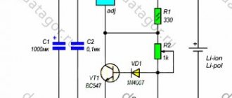
The battery voltage (maximum value 20 V) is measured using a voltage divider across resistors with R10, R13, R16. Adjust the tuning resistor R16 so that the value on the display (in actual voltage display mode) is equal to the actual battery voltage.
The battery is discharged through transistor VT1 (IRLB8743). The discharge current is measured on shunt R19 (0.24 Ohm). The discharge current is stabilized by an operational amplifier (op-amp) DD2 MC33171. The reference voltage is obtained using pulse width modulation (PWM) from the OC1A pin (PB1 - pin 15) of the microcontroller.
The PWM signal passes through a voltage divider (R12, R14, R17) and a low-pass filter (C7), creating a constant voltage proportional to the desired discharge current. Next, the voltage at the gate of VT1 is controlled by the op-amp, so that the voltage at shunt R19 corresponds to this reference voltage.
AE300 12V Battery Tester
Hello. In my review today I will talk about the battery tester. It is in no way a measuring device. You can call it a battery conductivity tester, a battery analyzer, a battery condition indicator, or simply a “display meter”. But this does not change its essence. It will allow you to quickly find out the status of your car's battery or uninterruptible power supply. This type of tester is able to determine whether the battery is in good condition, whether it needs to be recharged or whether it is time to change it. If you are interested, welcome to cat. I'll warn you right away. These testers are not designed to measure the cold cranking current (CCA) of new batteries - they are designed to test and evaluate the condition of used batteries. Any readings from the SSA or the current state of health of the battery cannot be considered completely reliable.
So, what is cold cranking current in a battery? And this is one of the most important characteristics of a battery. If the battery capacity only affects the number of attempts to start your car, then the cold cranking current is the maximum current supplied by the battery for 3 to 30 seconds at a temperature of -18 degrees (this depends on the measurement method. We mainly use the EN standard) . On the labeling of car batteries, in addition to the capacity, this value must be present. Starting current is a relative value. And it is very different in a new and old battery. Therefore, it is better to choose a battery with a reserve of starting current, so that over time you do not experience problems with starting. Especially in cold weather. For example, if your starter draws 250 amps, you should not choose a battery with a starting current of less than 350 amps. Otherwise, your battery will face a premature death. But let's not talk about sad things...
So, as I wrote above, our most common method for determining the cold cranking current is EN:
EN (European standard EN 50342.1 2006, formerly EN 60095-1)
The test is also carried out at -180C. EN requirements are divided into 2 methods – EN1 and EN2.EN1 – The battery voltage after 10 seconds should be 7.5 V. Then a break is made for 10 seconds, and the battery is discharged further at the initial current multiplied by 0.6. The second stage lasts 73 seconds, and in total the entire discharge period takes 90 seconds (assuming the initial period is 10 seconds / 0.6 = 16.7 seconds).
EN2 – Same as EN1 except the second discharge period is carried out to 6V for 133 seconds and the total test time is 150 seconds. The ratio of discharge currents corresponding to both methods largely depends on the type of battery and can vary from vehicle to vehicle and from design to design. Based on the comparative analysis, the following relationship between EN1 and EN2 can be derived:
EN2 = 0.85% to 0.92% EN1.
The tester checks the cold cranking current in other units. At CCA. But this is not a problem, there is a small sign that will help with this:
You can do without this sign. Roughly speaking, CCA is higher than EN by about 10%.
The first such testers under the “Pendant” brand were and are produced by a Russian manufacturer. But these testers cost, and still cost, a lot of money. If you are interested, you can find the price yourself so that I am not accused of advertising.
Therefore, it’s time to go directly to the hero of today’s review and see how this tester assesses the condition of the battery.
The order was made on December 6th. Or rather, a pre-order was made. And, after the AE300 tester became available, it was shipped on December 27 by a courier company. And, since there is no representative office in my city, the company sent a package from the city closest to me using EMS and on January 18, just on my birthday, I had it:
Plastic bag
The tester itself comes in blister packaging:
In addition to the tester, the kit includes instructions in English:
Instructions
And here is the hero of today's review - the AE300 battery tester:
The crocodiles are made of high quality and have contact pads made of non-ferrous metal:
Each crocodile has two wires, each soldered to its own contact pad on both sides:
The opening width of crocodiles is 3 centimeters:
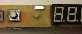
There are five buttons on the front panel of the tester:
The up and down arrows are used to select the CCA digits of the battery before starting the measurement, the “SEL” button selects the digit of the number. Button “OK” - serves to confirm and also start testing. On/off button – serves, as you might guess, to turn the tester on and off. The tester does not have its own power source and is powered by a connected battery.
On the back there is a sticker with the name of the tester:
Let's open it up:
The tester determines the internal resistance of the battery using the Whitson bridge principle.
When measuring with a tester, the battery is not discharged and a whole series of measurements can be carried out without the risk of draining the battery, which is impossible with other testing methods, for example, with a discharge or a load fork.
But then the calculations of the SSA calculation algorithm based on internal resistance come into play:
The tester uses an eight-bit microcontroller with flash memory – HOLTEK HT67F489:
Unfortunately, it is not known what formulas and constants for calculating capacity are programmed into the controller. How the firmware of the “Pendant” tester is still unknown. But be that as it may, it works.
AE300 board from the front:
So, the tester allows you to check the CCA of the battery. But what if you need to check a battery where CCA is not indicated? For example, a battery from a UPS? You can check it!
And although, as I wrote above, the tester was created to test batteries that are already in use, only a new one was at hand, out of the box for a 7 Ah UPS:
Let the readings be incorrect, but using his example I will tell you how to check batteries that do not have the CCA current indicated.
There is a formula according to which the approximate SCA of a battery is equal to the battery capacity divided by 0.0725. Later, in the video, using the example of a UPS battery that has already worked, you will be able to see that this value was chosen quite correctly. Based on this, you can convert the CCA value of similar batteries obtained by the tester into Ah by multiplying the resulting value by the same constant - 0.0725. Just remember, this is an approximate capacity that allows you to assess the condition of the battery.
So, since the battery is 7 Ah, we divide 7 by 0.0725. We get 96.55. The closest value that can be set on the tester is 95.
We connect the tester first to the positive and then to the negative of the battery, observing the polarity. Press the power button. The screen will start counting from 0 to 9. After the countdown, press the “OK” button, otherwise the countdown will be repeated until you press the button.
4 zeros will appear, the digit of the number that can be changed will blink. Set the desired value using the up/down arrows. The digit of the number is changed with the “SEL” button:
When the required value is entered, click the “OK” button. The measurement will begin, taking literally a few seconds:
When the measurement is completed, the results will be displayed on the tester screen and periodic beeping will be heard. Click "OK". The beeping will turn off.
So what do we see? And we see the bar at the top, filled to 100%. This is the general condition of the battery's life. The status is written above the stripe. If the condition is poor, you should consider purchasing a new battery.
Below is the voltage, measured quite accurately. Given that the multimeter measures correctly.
And the bottom line is the internal resistance of the battery. For batteries for a 7 Ah UPS it should be within 20-25 mOhm. If the resistance is higher, the battery must be replaced.
Press the “SEL” button and get to the second measurement page:
And, if everything is correct on the first page, then the second page will be unreliable, since the battery is new and has not yet been used.
095 is the SSA we recorded.
130.9 is the measured SSA. This will happen with new batteries. But, for example, when buying a new one, you can take a measurement and focus more on internal resistance than on capacity. Although a measured SCA that is less than expected is a reason to be wary, is the store selling you a battery that had been lying on the shelf for several years before being sold? And it’s better not to buy such a battery.
After the measurement, press the shutdown button, and then disconnect the negative clamp from the battery, and then the positive one.
Let's move on to the car battery.
The battery has been in use for three and a half years. The measurements were performed at negative temperatures. Accordingly, the parameters will be slightly underestimated. The amendments are also written in the instructions for the tester.
As you can see, the starting current of 520A (EN) is indicated here on the battery case. Let's transfer him to SSA. According to the table at the beginning of the review, 520A EN = 550 CCA. Therefore, before measuring, enter the number 550 into the tester and measure:
Battery internal resistance = 7.21 mOhm. For car batteries, the internal resistance standard is 5 - 8 mOhm. If the resistance is higher, it's time to change the battery.
The overall battery life is slightly above 60%. Which is rated by the tester as OK, in contrast to GOOD in the case of the UPS battery. When the battery condition is from 40 to 60%, it’s time to think about replacing it. Less than 40% - you risk not starting even in summer.
Use the “SEL” key to switch to the second screen:
With the specified cold cranking current of 550A SCA, we have only 324.7A SCA. This suggests that by next winter you should think about replacing the battery.
I shot a short video, although not of very high quality, since it was inconvenient to shoot a video with a camera while manipulating the tester. But in the video you can see the results of measuring various batteries, and there will also be several sequential measurements to check the repeatability of the result:
Well, the most valuable thing is the ability to assess the condition of the batteries without disconnecting them from the circuit. This is very convenient, especially when there are hundreds of batteries. I have already been able to identify many batteries that are on the verge of exhaustion and require replacement. Selective testing of batteries rejected by the tester confirmed that he was right.
Thank you for your attention.
The product was provided for writing a review by the store. The review was published in accordance with clause 18 of the Site Rules.
Calibration process
Set trimming resistor R18 to the central position. Connect a battery with a discharge current of at least 2.56 A and an ammeter in series. Set the desired discharge current to 2.56 A, start discharge (long press the SA1 button). Then set the trimming resistor R17 so that the actual discharge current is equal to the selected value (2.56 A).
Next, set the discharge current to 0.01A. Then adjust the bias of the DD2 op-amp inputs using R18 - set R18 so that the actual current is 0.01A.
Power transistor VT1 must be placed on a heatsink corresponding to the maximum required power dissipation during discharge (P = U*I). Transistor VT1 (IRLB8743) is a MOSFET with TTL logic that can operate at 5 V. If you are using a standard MOSFET type, then theoretically you can power the op amp from a higher voltage (this could be the voltage at the 7805 input), but I recommend logic MOSFET.
The HL1 LED indicates that discharge and measurement are in progress. Diodes VD1 and VD2 (1N4148) ensure complete blocking of transistor VT1 when the discharge process is not active.
To control the controller, use the SA1…SA3 buttons. A 4-digit LED display with a common anode is used as a display device. The display cathodes are connected to port D, the anodes are connected to bits 2-5 of port B. The display can be LD-D036UPG-C, LD-D028UR-C, LD-D036UR-C or LD-D056UR-C (very high brightness). The ultra-bright display eliminates the need for conventional transistors to amplify the anode current.
Display control is multiplex. The multiplexing frequency is about 100 Hz. Resistors R1 ... R8 determine the current of the display segments and, therefore, its brightness. They are selected so that the current does not exceed the maximum output current of the microcontroller pin (40 mA).
The battery capacity tester is powered by a power source with a voltage of 8 - 30V. The current consumption is about 15-45 mA, depending on the number of illuminated indicator segments and the resistance of resistors R1 ... R8. Capacitors C1, C2 and C3 should be located as close to the microcontroller as possible.
Connect an appropriate fuse in series with the battery being tested, otherwise tester failure (for example, current control failure or VT1 short circuit) or incorrect battery polarity may cause a fire! It is also recommended to use a fuse on the + input of the power supply.
DIY load fork
Simple to make and inexpensive, the device will be useful in the garage of any car enthusiast. With the help of this device it will be possible to carry out continuous diagnostics of the power source, as well as the generator. If you do not have the necessary amount to purchase a load fork, you can make it yourself.
Material used
When making a fork, you may need the following materials:
- to measure voltage you will need a voltmeter, if we use an analog one, then it should have a measurement limit of up to 20 V;
- insulated wires up to 6 mm thick, designed for high current values;
- at the end of the wires you should use special powerful clamps made of chrome steel;
- frame made of non-flammable materials;
- holder made of rubberized steel.
Important! When making a homemade load plug, it is recommended to use wires and devices designed for maximum operating current values.
Scheme
Single Spiral Load Fork:
Load fork with two spirals:
where R is resistance in the form of spirals or a set of resistors;
S - switches or switches;
V - voltmeter device.
When measuring a battery with a capacity of up to 100 Ah, one resistance must be used; when testing a battery with an internal capacity above 100 Ah, two or more resistances are used.