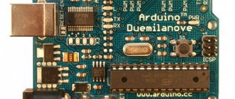
Arduino Uno board is the center of the large Arduino empire, the most popular and most affordable device. It is based on the ATmega chip - in the latest revision of Arduino Uno R3 it is ATmega328 (although you can still find variants of the UNO board with ATmega168 on the market). Most Arduino developers start with a UNO board. In this article we will look at the main features, characteristics and design of the Arduino Uno board revision R3, power requirements, possibilities for connecting external devices, differences from other boards (Mega, Nano).
Arduino Uno board
The Uno controller is the most suitable option for starting to work with the platform: it has a convenient size (not too large like the Mega and not as small as the Nano), is quite accessible due to the mass production of all kinds of clones, and there are a huge number of free ones written for it lessons and sketches.
Arduino Uno Specifications
| Microcontroller | ATmega328 |
| Operating voltage | 5V |
| Supply voltage (recommended) | 7-12V |
| Supply voltage (limit) | 6-20V |
| Digital inputs/outputs | 14 (of which 6 can be used as PWM outputs) |
| Analog inputs | 6 |
| Maximum current per pin | 40 mA |
| Maximum pin output current 3.3V | 50 mA |
| Flash memory | 32 KB (ATmega328) of which 0.5 KB is used by the bootloader |
| SRAM | 2 KB (ATmega328) |
| EEPROM | 1 KB (ATmega328) |
| Clock frequency | 16 MHz |
Images of Arduino Uno boards
The original board looks like this:
Original and official Arduino Uno
Numerous Chinese variants look like this:
The board is an Arduino Uno clone
More board examples:
General information
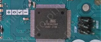
Arduino Uno controller is built on ATmega328 (technical description, pdf). The platform has 14 digital inputs/outputs (6 of which can be used as PWM outputs), 6 analog inputs, a 16 MHz crystal oscillator, a USB connector, a power connector, an ICSP connector, and a reset button. To operate, you need to connect the platform to your computer via a USB cable, or supply power using an AC/DC adapter or battery.
What does the Arduino uno circuit consist of?
Unlike all previous boards that used an FTDI USB microcontroller for USB communication, the new Arduino Uno uses an ATmega8U2 microcontroller. “Uno” is translated as one from Italian and the developers are thereby hinting at the upcoming release of Arduino 1.0. The new board has become the flagship of the Arduino board line. For comparison with previous versions, you can refer to the complete list of Arduino boards.
Where to buy Arduino Uno
The minimum prices for UNO boards can be found in Chinese electronic stores. If you have a few weeks to wait, you can save a lot by buying cheap (around 200-300 rubles) with free delivery. Moreover, you can find both the simplest options and official or “almost original” boards based on the original microcontroller. Another group of products are unusual boards with built-in WiFi (based on ESP8266 or ESP32), additional connectors for more convenient connection of peripherals. Here are some options that you can buy from trusted suppliers on Aliexpress:
| Arduino UNO R3 (CH340G) MEGA328P. A typical representative of Arduino boards on Aliexpress with a price below 250 rubles | High-quality Arduino UNO R3 board based on CH340G. Set without cable with a minimum price of about 220 rubles | Arduino wholesale – 10 UNO R3 controller boards with MEGA328P ATMEGA16U2 on board |
| Official Arduino UNO R3 MEGA328P based on ATMEGA16U2 – maximum quality | MegaPower Uno board based on the original ATmega328 R3, FTDI FT232RL | Original Arduino UNO R3 (board based on original MEGA and ATMEGA16U2 chips) with USB cable in a cardboard box |
| Two in one! Arduino UNO with built-in Sensor Shield (Atmega328P Atmega16U2 plus Sensor I/O Shield) | Arduino Uno and WiFi under one roof: R3 ATmega328P+ESP8266 (32Mb memory) | An excellent option from KeyeStudio – UNO R3 MEGA328P ATMEGA16U2 with combined Sensor Shield |
If you are interested in Arduino kits, you can find a more detailed overview of the available options on our website.
Peculiarities
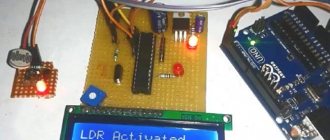
When someone talks about Arduino, they are most likely talking about an electronic circuit board called Arduino Uno. This is a board with a microcontroller. Using it, you can create and manage completely different projects: a motion sensor, a temperature sensor, you can create a robot that will bring you slippers. Everything is limited only by a person’s imagination and financial resources. For example, if you create a smart home system using Arduino, you will have to spend money.
Connecting arduino uno.
Arduino can be compared to a computer motherboard, which also has a processor located under the cooler. The motherboard with the processor performs the same functions as the Arduino Uno. Other devices are connected to it: display, disk drives, hard drives, and all other peripherals. You can also connect many different devices. Of course, fruitful work requires some knowledge: circuit design, electronics, and even the basics of programming in C++. However, believe me, it is not difficult if you consider and study everything in detail.
The board shown above is not the only board in this family. There are many boards with different microcontrollers and different characteristics for different purposes. However, Arduino UNO is the most popular and best suited for first projects. This is not an original board. The original ones are very expensive. They are sent from Italy in cardboard boxes, not plastic bags. But Chinese clones are also quite functional and can replace original boards at a reasonable price.
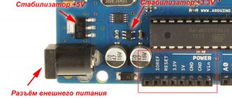
Design features
The figure shows those elements without which it is impossible to understand the device. A USB port is needed to connect the board to a computer, to create and download a work program to it. Also, when using this connection, input power is supplied via the USB port. The power supply plug is not particularly necessary for operation, since the USB port is used for power. When connecting power from an external source and from USB at the same time, power from the USB port is automatically turned off. In this case, the operation of the device is provided by an external power source.
RESET - This button is used to reset the microprocessor to the original settings that were programmed into it before connection.
The indicator LED shows that the Arduino is turned on and is an element of the circuit. The device has outputs and inputs to which controlled external devices are connected. These devices, in turn, also exert a control effect on the board. Inputs and outputs have their own numbering. Output No. 13 corresponds to the built-in LED.
Design features of arduino Uno.
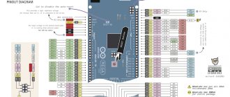
Circuit diagram and pinout of the board
Arduino is an open platform. In fact, anyone can download the circuit diagram from the official website or one of the popular forums, and then assemble a board based on the ATmega controller. The necessary electronic components can be purchased very inexpensively from many online stores.
Pinout of board based on ATMEGA 328
Schematic diagram:
Description of Arduino Uno R3 board elements
ATMega 328 microcontroller pinout
physical characteristics
Arduino Uno has the following dimensions: length 69 mm and width 53 mm. However, the power connector and USB connector protrude slightly from the PCB. Arduino Uno weighs about 25 grams. The board has 4 holes to allow it to be mounted on a surface. The distance between the pins is 2.5 mm, except for pins 7 and 8. There is 4 mm between them.
Schematic diagram
Schematic diagram of Arduino Uno
Description of Arduino pins
Arduino pins are used to connect external devices and can operate in both input mode (INPUT) and output mode (OUTPUT). A built-in 20-50 kOhm resistor can be connected to each input by executing the pinMode() command in INPUT_PULLUP mode. The permissible current at each output is 20 mA, no more than 40 mA at peak. For ease of use, some pins combine several functions:
- Pins 0 and 1 are UART contacts (RX and TX, respectively).
- Pins 10 to 13 – SPI pins (SS, MOSI, MISO and SCK respectively)
- Pins A4 and A5 are I2C pins (SDA and SCL, respectively).
Uno board digital pins
Pins numbered 0 to 13 are digital. This means that you can only read and apply two types of signals to them: HIGH and LOW. With PWM you can also use digital ports to control the power of connected devices.
| Arduino pin | Addressing in a sketch | Special appointment | PWM |
| Digital pin 0 | 0 | RX | |
| Digital pin 1 | 1 | TX | |
| Digital pin 2 | 2 | Interrupt input | |
| Digital pin 3 | 3 | Interrupt input | PWM |
| Digital pin 4 | 4 | ||
| Digital pin 5 | 5 | PWM | |
| Digital pin 6 | 6 | PWM | |
| Digital pin 7 | 7 | ||
| Digital pin 8 | 8 | ||
| Digital pin 9 | 9 | PWM | |
| Digital pin 10 | 10 | SPI (SS) | PWM |
| Digital pin 11 | 11 | SPI (MOSI) | PWM |
| Digital pin 12 | 12 | SPI (MISO) | |
| Digital pin 13 | 13 | SPI (SCK) A built-in LED is also connected to the output (available in most Arduino boards) |
Arduino Uno analog pins
Analog pins of Arduino Uno are designed for connecting analog devices and are inputs for the built-in analog-to-digital converter (ADC), which in Arduino Uno is ten-bit.
| Pin | Addressing in a sketch | Special appointment |
| Analog pin A0 | A0 or 14 | |
| Analog pin A1 | A1 or 15 | |
| Analog pin A2 | A2 or 16 | |
| Analog pin A3 | A3 or 17 | |
| Analog pin A4 | A4 or 18 | I2C (SCA) |
| Analog pin A5 | A5 or 19 | I2C (SCL) |
Additional pins on the board
- AREF – provides a reference voltage for the built-in ADC. Can be controlled by the analogReference() function.
- RESET – applying a low signal to this input will reboot the device.
Arduino - Communication Pins - I2C Interface
Arduino also has an I2C bus that allows communication between two components. For the UNO R3 board, I2C communication is implemented using two pins:
- SDA (Data Series) - pin “ A4 ” for data transmission via the I2C bus
- SCL (Serial Clock) - pin “ A5 ” of the clock signal, synchronizing data transfer on the I2C bus in both directions
Each external device that communicates with the Arduino via the I2C bus has its own unique address, for example 0x23. Up to 255 devices can be connected to one bus simultaneously.
Connecting devices
Any devices are connected to the board by connecting to the contacts located on the controller board: one of the digital or analog pins or power pins. A simple LED can be connected using two pins: ground (GND) and signal (or power pin).
The simplest sensor will require at least three contacts: two for power, one for signal.
With any option for connecting an external device, you should remember that using the board as a power source is only possible if the device does not consume more than the permitted current limit of the controller.
How-to video:
Supply system
In order for the Arduino Uno board to function, it must be powered. This can be done in several ways, namely:
- Power directly through the USB connector using a cord for programming or connection with a PC;
- Power it from an AC/DC adapter with an output voltage of 7-12V, connecting through a special external power connector.
- Apply a voltage of 7-12V directly to the Vin input, which is located on the pin block of the power supply group. In this case, the negative contact of the power supply should be connected to one of the GND contacts of the board.
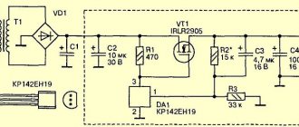
Also, the Arduino Uno board provides the user with two contacts with voltages of 5V and 3.3V. These voltages are generated by built-in linear stabilizers for any of the above power supply methods. The maximum current that the 3.3V output can provide is 50mA. Some “craftsmen” power the board through one of these pins, but this is fraught with failure of the latter, since the input voltage bypasses the stabilizer and any jump will simply burn the microcontroller.
Interesting read: How to convert an ordinary switch into a walk-through one.
The GND output speaks for itself and is a general disadvantage. All GND pins on the board are connected to each other. It should be noted that most of the strange glitches in working with the Arduino Uno board are associated with the fact that the project developer forgets to connect the GND pin of the Arduino board with the corresponding pins of other modules and sensors that are used in the project. The IOREF pin serves to inform modules or shields connected to Arduino Uno about the on-board voltage level. If the plug-in module has the ability to work with both 5V and 3.3V, then by reading the value on the IOREF pin, it can select the appropriate operating mode for itself.
How does arduino uno work?
Arduino Uno Power Options
The operating voltage of the Arduino Uno board is 5 V. A voltage stabilizer is installed on the board, so power can be supplied to the input from different sources. In addition, the board can be powered from USB devices. The power source is selected automatically.
- Powered by an external adapter, recommended voltage is from 7 to 12 V. The maximum voltage is 20 V, but a value above 12 V will most likely quickly damage the board. Voltage less than 7 V may lead to unstable operation, because 1-2 V can easily be lost at the input stage. To connect power, you can use the built-in 2.1 mm DC connector or directly the VIN input to connect the source using wires.
- Powered by the computer's USB port.
- Supply 5V directly to the 5V pin. In this case, the input stabilizer is bypassed and even the slightest excess voltage can lead to damage to the device.
Power pins
- 5V – Arduino supplies 5V to this pin, it can be used to power external devices.
- 3.3V – a voltage of 3.3 V is supplied to this pin from the internal stabilizer
- GND – ground output.
- VIN – pin for supplying external voltage.
- IREF – pin for informing external devices about the operating voltage of the board.
Uno sizes
Arduino Uno R3 is the most popular board based on the ATmega328 processor. Depending on the specific model of the board in this line, various microcontrollers are used; at the time of writing, the most common version is R3.
The board is used for training, development, and creation of working prototypes of devices. Arduino, at its core, is an AVR microcontroller with simplified programming and development capabilities. This was achieved using a specially prepared bootloader flashed into the MK’s memory and a proprietary development environment.
Arduino Uno board
The dimensions of the board are shown in the diagram below. The overall dimensions of the Uno are 53.4 mm by 68.6 mm .
Arduino Uno R3 memory
The Uno board supports three types of memory by default:
- Flash – 32 kB memory. This is the main repository for teams. When you flash a controller with your sketch, it is written here. 2kB from this memory pool is allocated to the bootloader program, which initializes the system, boots via USB and runs the sketch.
- 2 kB SRAM memory. By default, variables and objects created during program operation are stored here. This memory is energy-dependent; when the power is turned off, all data will, of course, be erased.
- Non-volatile memory (EEPROM) with a capacity of 1kB. Here you can store data that will not be erased when the controller is turned off. But the procedure for writing and reading EEPROM requires the use of an additional library, which is available in the Arduino IDE by default. Also be careful to remember the write cycle limitations inherent in EEPROM technology.
Some modifications to the standard Uno board may support higher memory values than the standard version. But you should understand that additional libraries will be required to work with them.
Arduino - digital pins with PWM signal generation function
In addition to their standard functionality, some digital pins are used to generate a PWM signal. Arduino PWM outputs : "D3", "D5", "D6", D9", "D10" and "D11". The default Arduino PWM frequency is 490 Hz.
The duty cycle value determines during what part of the period the digital pin is low. For example, if the duty cycle of a PWM signal is 40%, then at a peak voltage of 5V, the average voltage of such a signal will be 2V. Accordingly, the higher the duty cycle value, the higher the average value of the PWM signal.
Popular applications that use PWM signals include motor speed controllers, LED lighting dimmers, and music synthesizers.
Programming for the Uno Board
To write programs (sketches) for the Arduino controller, you need to install a programming environment. The easiest option would be to install the free Arduino IDE; you can download it from the official website.
After installing the IDE, you need to make sure that the correct board is selected. To do this, in the Arduino IDE, in the “Tools” menu and in the “Board” sub-item, select our board (Arduino/Genuino Uno). After selecting the board, the project's build parameters will automatically change and the final sketch will be compiled into a format that the board supports. By connecting the controller to your computer via USB, you can upload your program to it with one touch using the “Download” command.
The sketch itself most often represents an endless loop in which pins with attached sensors are regularly polled and, using special commands, a control action is generated on external devices (they are turned on or off). An Arduino programmer has the opportunity to connect ready-made libraries, both built into the IDE and available on numerous sites and forums.
The written and compiled program is loaded via a USB connection (UART-Serial). On the controller's side, the bootloader is responsible for this process.
More detailed information about how programs for the Arduino board are organized can be found in our section on programming.
Programming and communication with PC
In the upper left corner (Figure No. 3) there is a USB connector. It performs two functions. The first is the organization of a data exchange channel between the microcontroller and the PC and the second is the recording of firmware in the ATMega328. At the hardware level, the serial data transfer interface module (UART), which is built into the ATMega328 and located on pins 0 (RX) and 1 (TX) of the Arduino Uno board, is responsible for communication with the computer. However, simply transferring data to a computer will not work. The intermediary between the ATmega328 and the computer is a separately installed ATMega16 microcontroller.
Its special firmware allows you to define the Arduino Uno board as a virtual COM port when it is connected to a PC. Data exchange will be accompanied by blinking of the corresponding RX and TX LEDs located to the right of the ATMega16.
As for writing the firmware, this process is as simplified as possible and comes down to pressing just one button in the Arduino IDE. This simplicity is due to the fact that Arduino Uno is available with a built-in firmware bootloader that works using the STK500 protocol. Therefore, there is no need for an external programmer. However, for those who like to flash the controller directly, the board has an ICSP header (middle right) for in-circuit programming, bypassing the bootloader. The DFU bootloader itself is located in the ATMega16 and can also be rewritten by in-circuit programming through a similar block in the upper left part of the board.
Using an arduino uno circuit.
Difference from other boards
Today you can find many options for Arduino boards on the market. The most popular competitors of Uno are Nano and Mega boards. The first is suitable for projects in which size is important. The second is for projects where the circuit is quite complex and many outputs are required.
Differences between Arduino Uno and Arduino Nano
Modern Arduino Uno and Arduino Nano boards, version R3, usually have a common microcontroller on board: ATmega328. The key differences are the size of the board and the type of pads. Dimensions of Arduino Uno: 6.8 cm x 5.3 cm. Dimensions of Arduino Nano: 4.2 cm x 1.85 cm. Arduino UNO uses female connectors, Nano uses a “comb” of legs, and some models, the contact pads are not soldered at all. Naturally, the larger size of UNO compared to Nano is an advantage in some cases, and a disadvantage in others. With a large board it is much more convenient to install, but it is inconvenient in real projects, because greatly increases the dimensions of the final device.
Arduino Uno boards traditionally use the TYPE-B connector (also widely used for connecting printers and MFPs). In some cases, you can find an option with a Micro USB connector. On Arduino Nano boards, Mini or Micro USB is standard.
Naturally, there are differences in the power connector. The Uno board has a built-in DC connector; there was simply no place for it in the Nano.
In addition to the hardware, there are also small differences in the process of loading the sketch into the board. Before downloading, you should make sure that you have selected the correct board in the "Tools-Board" menu.
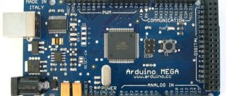
Differences from Arduino Mega
The Mega board, in full accordance with its name, is by far the largest Arduino controller in terms of size and number of pins. Compared to it, Uno has much less pins and memory. Here is a list of the main differences:
- The Mega board uses a different microcontroller: ATMega 2560. But its clock frequency is 16 MHz, the same as in Uno.
- The Mega board has a larger number of digital pins - 54 instead of 14 on the Uno board. And analog – 16/6.
- The Mega board has more pins that support hardware interrupts: 6 versus 2. More Serial ports - 4 versus 1.
- In terms of memory capacity, Uno is also significantly inferior to Mega. Flash memory 32/256, SRAM – 2/8, EEPROM – 4/1.
Based on all this, we can conclude that for large complex projects with large programs and active use of various communication ports, it is better to choose Mega. But these boards are more expensive than Uno and take up more space, so for small projects that do not use all the additional capabilities of Mega, Uno will do just fine - you won’t get a significant increase in speed when switching to the “bigger” brother.
Scope of application
The places of use can be listed for a long time, since its possibilities are unlimited. Using this device, you can design many different systems that will help a person in everyday life, as well as in industrial production, medicine and other areas of our lives. Currently, the world is experiencing “Arduinomania”. Many articles and forums on the Internet are devoted to this miniature device. Here are some popular uses for this device:
- “smart home” system;
- all kinds of sensors;
- robotics;
- automatic fans;
- traffic lights;
- security systems;
- mini weather stations;
- multitesters;
- quadcopters.
Advantages
- Open equipment diagrams and specifications. Arduino Uno is based on popular Amtel and ATMEGA microprocessors. Qualified specialists can design their own version of the module for specific tasks based on existing circuits.
- Open source program. Program coding can be extended on the C++ platform.
- Simple and convenient programming environment. The program shell is easy to use for novice programmers, but has sufficient flexibility for the work of professionals. It is most convenient for the learning environment of students, who will easily understand the operation of this platform.
- Programming, connection and power supply are performed using one USB cable or a cable with an adapter on the chip.
- Possibility of functioning on various types of systems. The software operates successfully on Linux, Macintosh, Java and other systems, as it is open source. However, the most popular system for Arduino has become the Windows system.
- Acceptable price. In big cities, Arduino Uno can be purchased for less than 1000 rubles. This is the price for a ready-made, complete device that does not require auxiliary equipment, expensive programmers, or paid programs.
Advantages and disadvantages.
Flaws
The program shell is too simple. This is a very inconvenient code editor. To program, you will have to switch to a more convenient editor, but you still need to leave the Arduino IDE code editor open. Low microprocessor frequency. There is no way to change it. Small amount of memory for saving programs.
It will be interesting➡ Arduino Nano: pinout and board diagram, characteristics, description
Brief conclusions
Arduino Uno is an excellent board option for creating your first projects and smart devices. 14 digital and 6 analog pins allow you to connect a variety of sensors, LEDs, motors and other external devices. The USB connector will help you connect to a computer to flash the sketch without additional external devices. The built-in stabilizer allows you to use various batteries with a wide voltage range, from 6-7 to 12-14 V. The Arduino Uno works quite conveniently with popular protocols: UART, SPI, I2C. There's even a built-in LED that you can flash in your first sketch. What more could a beginner Arduino user want?
Arduino - digital pins
The Arduino Uno has 14 digital pins (“D0” - “D13”) that can be configured as inputs or outputs. One of these pins "D13" is connected to the built-in LED.
The maximum current (load) of each digital pin is 20mA. Digital pins work with logic states: a low state means logic 0, and a high state means logic 1. If the Arduino's digital pins are configured as outputs, then low voltage is 0V and high voltage is 5V.
If digital contacts are configured as inputs that receive signals from external devices, then the logical levels will be different. Arduino interprets input voltage in the range of 0.0V - 0.8V as a low state ("0"), and in the range of 2.0V to 5.0V as a high state ("1"). The range 0.8V - 2.0V means a prohibited state in which there is no right to change the logical state.
Advantages and disadvantages
- Price. In Moscow, Arduino Diecimila can be bought for less than 1000 rubles. At the same time, you are buying a complete (well, almost) device that does not require additional equipment, such as expensive programmers and debugging stands, and does not require paid software.
- Cross-platform. Arduino software works on Windows, Macintosh OS X, Linux and other operating systems as it is open source and runs on Java. Most microcontroller systems are limited to Windows.
- Simple programming environment. The software interface is easy to use for beginners, but flexible enough for advanced users to quickly achieve the desired result. This is especially convenient in an educational environment, where students can easily understand the platform, and teachers can develop a course and assignments.
- Open source. The language can be extended with C++ libraries; more advanced specialists can create their own Arduino toolkit based on the AVR C compiler.
- Open specifications and equipment diagrams. Arduino is based on Atmel ATMEGA8 and ATMEGA168 microcontrollers. The module schematics are published under a Creative Commons license so experienced circuit designers can create their own version of the module to suit their needs. Even relatively inexperienced users can mock up a module to understand how it works and save money.
Among the shortcomings, I would like to note, perhaps, a rather poor software shell, a low processor frequency (which is actually quite high and, in addition, reduces power consumption) and a small amount of “disk” (flash) memory for programs. With such a clock frequency and memory capacity, it is unlikely that it will be possible to assemble a simple mp3 player. However, it is unlikely that anyone will try to make, say, a guided cruise missile based on Arduino. In addition, I could not find sane sources for assembling avr-gcc. Well, of course, you will have to know (or study in the process) the basics of electronics at the level of “plus/minus, resistor/capacitor” - there’s absolutely no way without this.
Communication with the outside world
To communicate with external devices (computer and other microcontrollers), there are several additional devices on the board. On pins 0 (RX) and 1 (TX), the ATmega328 controller supports UART - a serial data interface. ATmega8U2, which acts as a programmer on the board, broadcasts this interface via USB, allowing the platform to communicate with a computer through a standard COM port.
Expert commentary
Lagutin Vitaly Sergeevich
Engineer with a degree in Computer Software and Automated Systems, MEPhI, 2005–2010.
Ask a Question
The firmware installed in the ATmega8U2 controller has standard USB-COM drivers on board, so no additional drivers are required for connection.
Related material: What are SMD resistors used for?
On Chinese-made boards, instead of the ATmega8U2 controller, another programmer is used - CH340G, which is not automatically recognized by Windows. It requires installing an additional driver. Using serial bus monitoring called Serial Monitor, the Arduino IDE sends and receives data from the Arduino. When exchanging data, the RX and TX LEDs are visible blinking on the board. When using the UART interface via pins 0 and 1, the LEDs do not blink.
The board can communicate via the UART interface not only through hardware, but also through software. For this purpose, the Arduino IDE provides the SoftwareSerial library. Also, the board provides pins for the main interfaces for interaction with peripherals: SPI and I2C (TWI).
Interference and protection against it
If there are powerful consumers in the same power circuit with the Arduino, such as servos, addressable LED strips, relay modules, etc., noise may occur on the power line, leading to strong measurement noise from the ADC, and more powerful interference can cause interrupts and even change states pins, disrupting communication across various communication interfaces and introducing errors into sensor readings, displaying nonsense on displays, and sometimes it can even lead to the controller rebooting or freezing. Some modules can also freeze, reboot and fail if the power supply is poor, for example, a bluetooth module can easily freeze and hang until the system is completely rebooted, and rf24 radio modules will not work at all with a “noisy” power supply.
Moreover, interference can come from unexpected places - through the air, for example from an electric motor, the inductive surge is caught by wires and does all sorts of things to the system. What to do? “Big guys” in real industrial devices do a lot to protect against interference; entire books and dissertations are devoted to this. We will look at the simplest thing you can do at home on your knee.
- Power the logical part (Arduino, low-current sensors and modules) from a separate low-noise 5V power supply, that is, separate the power supply of the logical and power parts, or even better, feed the Vin pin from a 7-12V power supply, since the linear stabilizer gives a very good smooth voltage. For the correct operation of devices that are powered separately (motor drivers, drives), you need to connect the grounds of the Arduino and all external devices;
- Place capacitors to power the board , as close as possible to the 5V and GND pins: electrolyte 6.3V 100-470 uF (µF, the capacitance depends on the quality of the power supply: in case of strong voltage drops, install a larger capacitance; in case of slight interference, 10-47 µF is enough) and ceramic by 0.1-1 uF. This will smooth out noise even from servos;
- For “remote” elements of the system on the wires (buttons, knobs, sensors), twist the wires into a pigtail , mainly with the ground. It’s even better to use shielded wires; the screen will naturally be GND. This way we protect ourselves from electromagnetic interference;
- Connect all grounds with one thick wire and, if possible, ground to a central ground;
- The metal and grounded body of the device (or simply wrapped in foil?), to which all components of the circuit are grounded, is the key to the complete absence of interference and interference through the air.
An LC filter consisting of an inductor and a capacitor can handle noise filtering even better. The inductance should be taken with a nominal value in the region of 100-300 μH and with a saturation current greater than the load current after the filter. The capacitor is an electrolyte with a capacity of 100-1000 uF, depending again on the current consumption of the load after the filter. It is connected like this, the closer to the load, the better:
You can read more about calculating filters here.
Inductive emissions
In practice, the most vile interference usually comes when switching an inductive load using an electromagnetic relay: it is very difficult to protect yourself from such interference, because it comes along the ground, that is, even separate power supply of the project will not save you. What to do?
- For chains direct current Be sure to install a powerful diode in reverse parallel to the load, as close as possible to the relay terminals. The diode will accept (close) the inductive surge from the motor/coil;
- There, on the relay terminals, you can put an RC circuit, called in this case a spark-extinguishing circuit: a 39 Ohm 0.5 W resistor, a 0.1 uF 400V capacitor (for a 220V circuit);
- AC networks, use a solid-state relay (SSR) with a Zero-cross detector, also called “silent” relays. If in the AC circuit instead of a relay there is a triac with an optocoupler, then the optocoupler must again be used with a zero detector, such an optocoupler, like the SSR zero-cross, will turn off the load at the moment when the voltage in the network passes through zero, this minimizes everything emissions.
You can read more about spark arresting circuits in this manual.