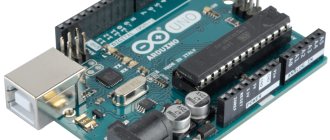
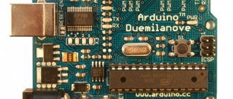
Arduino UNO pinout
Most Arduino models, including the most popular Arduino UNO R3, are equipped with an 8-bit AVR ATmega328P microcontroller. The tracks on the printed circuit board connect the pins of the microcontroller to the pin comb. Thanks to this, we can connect external devices such as Arduino Shield, LEDs, transistors, sensors, potentiometers and others to Arduino.
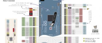
The Arduino UNO R3 pins include 14 digital pins, 6 analog pins, power headers, a USB header, and a header for an optional external USB-ASP programmer. The complete pinout diagram of the Arduino UNO R3 board is shown in the following figure:
RoboCraft
I think it’s no secret to anyone that the program is initially uploaded to the microcontroller using a special device - a programmer. Of course, Arduino people usually don’t need to worry about this - they have a bootloader pre-flashed into the microcontroller, and it picks up the firmware via UART via a COM port or via USB. But to flash this bootloader or other firmware into a “clean” MK, you need a programmer.
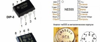
But in this article we will not consider assembling and soldering the programmer from scratch, but will use the capabilities of Arduino. The fact is that most Arduino boards up to the Uno version have an FT232RL
FTDI company. This chip is a UART->USB converter, providing the operating system with a virtual COM port that works via USB. But in this case, we need another of its capabilities - control of individual pins of the chip, called the bit-bang mode, which allows you to “wrap” an arbitrary protocol in USB. The task is to wrap the MK firmware protocol in USB.
The AVR microcontrollers used in Arduino are flashed using the already familiar SPI protocol via a connector for in-circuit programming - ISP
(
I
n-
System
P rogramming
). It is so called because it allows you to flash the MK directly in the final device. This is what this connector looks like on the CraftDuino board:
MISO, MOSI, SCK, RESET - these are all SPI bus lines, only instead of SS - RESET.
But we still need access to the FT232RL pins, through which the firmware will be carried out, and the Arduino developers took care of this by making the X3
(x-three):
If your board only has pads for X3, you will need to solder a piece of PLS comb yourself.
The pins of this connector have the following purpose for the ISP programmer:
- 1 (CTS) - MISO
- 2 (DSR) - SCK
- 3 (DCD) - MOSI
- 4 (RI) - RESET
And instead of X3, CraftDuino has a standard RS232 connector, also connected to FT232RL, from which we need the same 4 outputs:
- 1 (CD) - MOSI
- 6 (DSR) - SCK
- 8 (CTS) - MISO
- 9 (RI) - RESET
Having brainstormed, we’ll make a cable for our improvised ISP programmer:
At one end of the cable there are connectors for Arduino X3/CraftDuino UART, and for power:
And at the other end there is a standard ISP connector:
Typically, the popular avrdude
, which supports many different programmers and MK models; even the Arduino IDE uses it to upload a sketch.
There is a patch for this utility that allows you to flash the MK through the FT232RL chip using the bit-bang mode. There were kind people who had already patched the Windows version of avrdude
to work with a bit-bang programmer based on this chip, and I did the same for Linux:
- Patched version 5.3.1 for Windows.
- Version 5.10, deb package for Linux i386 and amd64 (x86_64).
- An archive with the source code of version 5.10, the libftd2xx-1.0.4 library from the official FTDI website and the corrected Makefile.in
and
avrdude.conf
so that all this is assembled, installed correctly and works. I only tested it on Ubuntu 11.04 (i386 and amd64).
Actually, the deb packages are compiled from the patched distribution posted here, but for the paranoid there is another option - to patch and build avrdude yourself, read about it here. Only in avrdude.conf
you need to add the following lines, and not what is written in the article at the link:
programmer id = “ftbb”;
desc = "FT232R Synchronous BitBang"; type = ft245r; miso = 3; # CTS X3(1) sck = 5; # DSR X3(2) mosi = 6; # DCD X3(3) reset = 7; # RI X3(4) ; If you're running Linux, you'll have to do a few more steps (FTDI loves us):
- Kill driver ftdi_sio
, which interferes
avrdude
open FTDI COM port: sudo rmmod ftdi_sioIf you wish, you can blacklist this kernel module by adding it to /etc/modprobe.d/blacklist.conf
line:
blacklist ftdi_sio
Just keep in mind that to work with the virtual port /dev/ttyUSB0and so on.
(needs Arduino IDE) this module must be running. This can be done with the command sudo modprobe ftdi_sio - By default, when avrdude tries to open the FTDI virtual COM port, the system will show it a cookie, and it will show you a not very informative error message. You need to give yourself full access rights to virtual COM ports by creating /etc/udev/rules.d/
file with name
80-ftdi.rules
the following content: SYSFS{idVendor}==»0403″, SYSFS{idProduct}==»6001″, MODE=»660″, GROUP=»ftdi-user»USB Vendor ID and Product ID can be clarified with the lsusb
, if the Arduino is connected to the computer:
... Bus 005 Device 012: ID 0403:6001 Future Technology Devices International, Ltd FT232 USB-Serial (UART) IC ...
Then you need to create the ftdi-userAnd add yourself to it:
Sudo AddGroup FTDI -User SUDO Usermod -G ftdi -User < However,Well, so that the udev
I found out about the changes, you need to either restart the computer or call
sudo udevadm trigger
In an article about programming AVR in C, comrade noonv has already described how to use avrdude
, and I will only describe uploading the bootloader to the Arduino Diecimila with ATmega168:
- We set the fuse bits necessary for fast bootloader firmware: quartz > 8 MHz, built-in divider by 8 is disabled: avrdude -c ftbb -P ft0 -p m8 -B 9600 -U hfuse:w:0xdd:m -U lfuse:w:0xff :m
- Load the bootloader: avrdude -c ftbb -P ft0 -p ATMega168 -B 19200 -U flash:w:ATmegaBOOT_168_diecimila.hex
But the console is not always better than the user interface, especially for setting fuse bits, and there is a much more convenient and reliable way - to use the SinaProg program, developed by Iranian programmers. Their website has long since died, but the program is alive and well to this day. Di Halt has written about its configuration in detail, but we won’t waste time and take a ready-made configured assembly with patched avrdude (there is an error in one of the configs in Di Halt’s assembly). Unfortunately, there is no version for Linux.
In the Hex file
a hex file is selected that needs to be uploaded or read.
You can write and read both program memory (Flash) and non-volatile memory (EEPROM). In the Device
you need to specify a specific MK, in the
Programmer
- the programmer (for us it is ftbb), port (FTDI0) and port speed (9600).
Well, the reason why you should use this program is the Fuses
.
In the drop-down list, you can select predefined fuse bit configurations that are specified in Fuse.txt. But the most important thing is revealed to our eyes by pressing the Advanced
:
Here you can enter fuse bytes manually, or you can press the “C” button next to the byte value and set fuse by clicking the checkboxes with descriptions. To load the bootloader, first press the Read
to read the current fuse values, and then configure
Low fuse
: quartz frequency - more than 8 MHz, MK start time - 65 ms, divider by 8 is turned off:
After setting, click the Write
and wait for the inscription “Writing Fuses... OK” to appear.
Now you can in the main window in the Hex file
select the bootloader file
ATmegaBOOT_168_diecimila.hex
and in the
Flash
press the
Program
.
If errors occur during the process, there is a “>” button above the progress indicator, which opens the avrdude
.
Let's flash some other MK - for example, ATtiny13
.
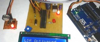
Let's put the MK on the breadboard, connect all the ISP connector lines from our bit-bang programmer to it, attach the LED through a 500 Ohm resistor to the 3rd leg ( DB4
) and pull
RESET
to the power supply with a 10 kOhm resistor:
In your favorite text editor, write a simple code for a simple LED flasher in the file blink.c
:
#include #include enum { LED_BIT = 1 << PORTB4 };
int main() { DDRB |= LED_BIT; while (1) { PORTB |= LED_BIT; _delay_ms(500); PORTB &= ~LED_BIT; _delay_ms(500); } } Compiling:
avr-gcc -DF_CPU=1200000 -Os -mmcu=attiny13 blink.c -o blink.out
Making a hex firmware file:
avr-objcopy -O ihex blink.out blink.hex
Upload to MK:
avrdude -c ftbb -P ft0 -p attiny13 -B 9600 -U flash:w:blink.hex
Loading started:
:~/tmp$ avrdude -c ftbb -P ft0 -p attiny13 -B 9600 -U flash:w:blink.hex avrdude: BitBang OK avrdude: pin assign miso 3 sck 5 mosi 6 reset 7 avrdude: drain OK ft245r: bitclk 4800 -> ft baud 2400 avrdude: AVR device initialized and ready to accept instructions Reading | ################################################## | 100% 0.00s avrdude: Device signature = 0x1e9007 avrdude: NOTE: FLASH memory has been specified, an erase cycle will be performed To disable this feature, specify the -D option. avrdude: erasing chip ft245r: bitclk 4800 -> ft baud 2400 avrdude: reading input file “blink.hex” avrdude: input file blink.hex auto detected as Intel Hex avrdude: writing flash (78 bytes): Writing | ################################################## | 100% 0.64s avrdude: 78 bytes of flash written avrdude: verifying flash memory against blink.hex: avrdude: load data flash data from input file blink.hex: avrdude: input file blink.hex auto detected as Intel Hex avrdude: input file blink.hex contains 78 bytes avrdude: reading on-chip flash data: Reading | ################################################## | 100% 0.50s avrdude: verifying … avrdude: 78 bytes of flash verified avrdude: safemode: Fuses OK avrdude done. Thank you.
We plug the Arduino into USB and observe the LED blinking, provided that there are no connection errors (:
So, with some simple manipulations with your hands and brains, you can make yourself a USB ISP programmer, so you don’t have to worry about the lack of LPT on modern computers and a COM port on almost any laptop - USB is everywhere.
Arduino - board power
How to connect Arduino to power . Like any other electronic device, the Arduino board needs to be connected to a supply voltage to operate. Power can be supplied to the Arduino UNO R3 in three ways.
- The first way is to use 5.5mm/2.1mm (round) power connector In this case, the output voltage should be in the range from 7V to 12V.
- The second method is to apply voltage to the “ VIN ” pin from an external source in the range from 7V to 12V. This can be a laboratory power supply or two 18650 connected in series. The VIN pin is connected to a rectifier diode, which prevents damage if the voltage is connected with reverse polarity.
- The third method - power can also be supplied via a USB type B connector - both when connecting the Arduino to a computer, and when powered from a smartphone charger. Please note that the computer's USB provides a maximum current of up to 500 mA.
The power of the power supply should be selected in accordance with the energy consumption of the device being developed. Regardless of the selected power source, the circuit must be connected to ground (GND). The Arduino board has five "GND" pins that are galvanically connected to each other.
RESET pin on the board , which, after a short circuit to ground, for example using a button on the board, causes a temporary power cut and restart of the Arduino.
An external voltage reference can be supplied to the Arduino via the "IOREF" pin.
Arduino kit
Keyestudio Super Starter Kit with V4.0 board for Arduino…
More details
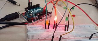
5Sketch for controlling a shift register via the SPI interface
Let's write a sketch that implements a “traveling wave” by sequentially lighting the LEDs connected to the outputs of the shift register.
#include const int pinSelect = 8;
// register select pin void setup() {
SPI.begin();
// initializing the SPI interface pinMode(pinSelect, OUTPUT); // digitalWrite(pinSelect, LOW); // select slave devices (register) SPI.transfer(0); // clear the contents of the register digitalWrite(pinSelect, HIGH); // end of transmission Serial.begin(9600); } void loop() {
for (int i=0; i}
First, let's connect the SPI library and initialize the SPI interface. Let's define pin 8 as the SS slave selection pin. Let's clear the shift register by sending the value "0" to it. Initialize the serial port.
To light a specific LED using a shift register, you need to apply an 8-bit number to its input. For example, to make the first LED light up, we supply the binary number 00000001, for the second – 00000010, for the third – 00000100, etc. These binary numbers, when converted to the decimal number system, form the following sequence: 1, 2, 4, 8, 16, 32, 64, 128 and are powers of two from 0 to 7.
Accordingly, in the loop() , we recalculate from 0 to 7 based on the number of LEDs. The pow(base, power) raises 2 to the power of the loop counter. the round() function to convert the result to an integer . And we transfer the resulting number to the shift register. For clarity, the values obtained during this operation are displayed in the serial port monitor: the unit “runs” through the digits - the LEDs light up in a wave.
Numbers sent to the 74HC595 shift register
Arduino - analog pins
Arduino UNO has 6 analog inputs (“A0” - “A5”). These inputs are connected via a multiplexer to the input of the analog-to-digital converter (ADC) of the ATmega328 microcontroller.
The ADC converts the input analog signal in the range of 0V-5V into digital form. The resolution of the ADC in Arduino is 10 bits. This means that the number of voltage levels at the converter input is 1023 with a resolution of 4.89 mV. The resolution can be expanded using a reference voltage below 5V, which is applied to the "AREF" pin.
The sampling frequency of the ADC converter is approximately 9600 Hz. The ADC will process data flawlessly as long as the signal is below half the ADC sampling frequency, i.e. no more than 4800Hz.
Typical applications using Arduino ADCs include analog sensors, potentiometers, and voice over IP (VoIP).
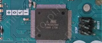
Arduino Mega 2560 board
The Arduino Mega 2560 device is assembled on the ATmega 2560 microcontroller (datasheet), and is an updated version of the Arduino Mega.
To carry out the conversion of USB-UART interfaces, a new microcontroller ATmega 16U2 (or ATmega 8U2 for versions of boards R1 or R2) is used.
The board composition is as follows:
- the number of digital inputs/outputs is 54 (15 of them can be used as PWM outputs);
- number of analog inputs – 16;
- Serial interfaces are implemented using 4 UART hardware transceivers;
- 16 MHz – quartz resonator;
- USB connector;
- power connector;
- in-circuit programming is carried out via the ICSP connector;
- reset button.
The Mega 2560 R2 version adds a special resistor that pulls the 8U2 HWB line to ground, which greatly simplifies the transition of the Arduino to DFU mode, as well as updating the firmware. Version R3 differs slightly from previous ones. The changes in the device are as follows:
- four pins were added - SCL, SDA, IOREF (to ensure voltage compatibility of various expansion boards) and another reserve pin, not yet used;
- increased noise immunity in the reset circuit;
- increased memory capacity;
- ATmega8U2 has been replaced by the ATmega16U2 microcontroller.
Arduino Mega 2560R3 pins are intended for the following:
- The available digital pins can serve as input/output. The voltage on them is 5 volts. Each pin has a pull-up resistor.
- Analog inputs do not have pull-up resistors. The operation is based on the use of the analog Read function.
- The number of PWM pins is 15. These are digital pins No. 2 - No. 13, No. 44 - No. 46. PWM is used through the analog Write function.
- Serial interface: Serial pins: №0 (rx), №1 (tx); Serial1 pins: No. 19 (rx), No. 18 (tx); Serial2 pins: No. 17 (rx), No. 16 (tx); Serial3 pins: No. 15 (rx), No. 14 (tx).
- The SPI interface is equipped with pins No. 53 (SS), No. 51 (MOSI), No. 50 (MISO), No. 52 (SCK).
- Pin No. 13 – built-in LED.
- Pins for communication with connected devices: No. 20 (SDA), No. 21 (SCL).
- For external interrupts (low signal level, other signal changes), pins No. 2, No. 3, No. 18, No. 19, No. 20, No. 21 are used.
- The AREF pin is enabled by the analog Reference command and is intended to regulate the reference voltage of the analog input pins.
- Reset output. Designed to generate a low level (LOW), which causes the device to reboot (reset button).
Arduino - digital pins
The Arduino Uno has 14 digital pins (“D0” - “D13”) that can be configured as inputs or outputs. One of these pins "D13" is connected to the built-in LED.
The maximum current (load) of each digital pin is 20mA. Digital pins work with logic states: a low state means logic 0, and a high state means logic 1. If the Arduino's digital pins are configured as outputs, then low voltage is 0V and high voltage is 5V.
If digital contacts are configured as inputs that receive signals from external devices, then the logical levels will be different. Arduino interprets input voltage in the range of 0.0V - 0.8V as a low state ("0"), and in the range of 2.0V to 5.0V as a high state ("1"). The range 0.8V - 2.0V means a prohibited state in which there is no right to change the logical state.
Arduino Mini board
It is one of the simplest and most convenient Arduino devices.
An ATmega 168 microcontroller with an operating voltage of 5 volts and a frequency of 16 MHz is used. The maximum supply voltage in models is 9 volts. The maximum current at the terminals is 40 mA.
The fee contains:
- 14 digital pins (6 of them can be used as PWM outputs), can be used as both input and output;
- 8 analog inputs (4 of them are equipped with pins);
- 16 MHz – crystal oscillator.
The pins of the Arduino Mini device have the following purposes:
- Two pins through which the plus board is powered: RAW, VCC.
- The minus contact output is the GND pin.
- Pins numbered 3, 5, 6, 9, 10, 11 are used for PWM when using the analog Write function.
- Other devices can be connected to pins No. 0, No. 1.
- Analog inputs No. 0 – No. 3 with outputs.
- Analog inputs No. 4 – No. 7 do not have pins and require soldering if necessary.
- AREF pin, which is designed to change the upper voltage.
- Reset output – reboot the microcontroller.
The pin layout may vary between different versions of arduino mini.
Arduino - digital pins with PWM signal generation function
In addition to their standard functionality, some digital pins are used to generate a PWM signal. Arduino PWM outputs : "D3", "D5", "D6", D9", "D10" and "D11". The default Arduino PWM frequency is 490 Hz.
The duty cycle value determines during what part of the period the digital pin is low. For example, if the duty cycle of a PWM signal is 40%, then at a peak voltage of 5V, the average voltage of such a signal will be 2V. Accordingly, the higher the duty cycle value, the higher the average value of the PWM signal.
Popular applications that use PWM signals include motor speed controllers, LED lighting dimmers, and music synthesizers.
Arduino Micro Board
Arduino Micro is a device based on the ATmega 32u4 microcontroller, which has a built-in USB controller. This solution simplifies connecting the board to a computer, since the system will recognize the device as a regular keyboard, mouse or COM port. The composition of the device is as follows:
- number of inputs/outputs – 20 (it is possible to use 7 of them as PWM outputs, and 12 as analog inputs); quartz resonator tuned to 16 MHz;
- micro-USB connector;
- ICSP connector designed for internal programming;
- reset button.
All digital pins of the product can work as both inputs and outputs thanks to the digital Read, pin Mode, digital Write functions. The voltage at the terminals is 5 volts. The maximum current consumed or supplied from one pin is 40 mA. The pins are connected to internal resistors, which are off by default. They have ratings of 20 kOhm - 50 kOhm. Separate arduino micro pins, in addition to the main ones, are capable of performing a number of additional functions:
- In the serial interface, pins No. 0 (RX), No. 1 (TX) are used to receive (RX) as well as transmit (TX) the necessary data through the built-in hardware transceiver. The function is relevant for arduino micro Serial class. In other cases, communication is via a USB connection (CDC).
- The TWI interface includes microcontroller pins No. 2 (SDA) and No. 3 (SCL). Allows you to use Wire library data.
- Pins numbered 0, 1, 2, 3 can be used as sources of interrupts. These include low signal level; interrupts on the edge, on the fall, when the signal level changes.
- Pins numbered 3, 5, 6, 9, 10, 11, 13, when using the analog Write function, are capable of outputting an 8-bit analog PWM signal.
- The SPI interface includes pins on the ICSP connector. They do not connect to digital pins on the board.
- Additional RX LED/SS pin, which is connected to the LED. The latter indicates the process of data transfer using USB. This pin can be used when working with the SPI interface for the SS pin.
- Pin No. 13 is an LED that turns on when sending HIGH data and turns off when sending LOW data.
- Pins A0 – A5 (marked on the board) and A6 – A11 (corresponding to digital pins numbered 4, 6, 8, 9, 10,12) are analog.
- The AREF pin allows you to change the upper value of the analog voltage on the above pins. This uses the analog Reference function.
- Using the Reset pin, a low level (LOW) is formed and the microcontroller is rebooted (reset button).
Arduino - Communication Pins - UART Interface
Arduino uses several interfaces to communicate with external devices. One of them is the UART (Universal Asynchronous Receiver-Transmitter). This is a serial protocol implemented using digital pins:
- “ D0 ” (“RX” is a receiver that receives a signal from an external device)
- “ D1 ” (“TX” is a transmitter that sends a signal to an external device)
UART provides communication with external modules, as well as with the computer to which it is connected via a USB connector.
Arduino - Communication Pins - SPI Interface
Another interface is SPI (Serial Peripheral Interface). It is a serial protocol that allows a microcontroller to communicate with one or more devices. This protocol provides synchronous communication with another microcontroller in the Master - Slave topology.
In Arduino UNO R3, the SPI bus has the following pins:
- SS (Slave Select) - pin “ D10 ” - selecting the address of the slave device with which the microcontroller should communicate
- SCK (Serial Clock) - pin “ D13 ” - clock signal synchronizing data transfer in both directions
- MISO (Master Input Slave Output) - pin “ D12 ” - line for sending information from slave devices to the master device
- MOSI (Master Output Slave Input) - pin “ D11 ” - line that sends information from the master device to the slave devices
Connecting SPI to Arduino
The Arduino board already contains special pins for connecting the SPI interface. The same pins are repeated in the hotel ICSP connector. There is no SS on this connector - it was originally intended that the Arduino microcontroller will act as a master device. If you need to use it as a slave, you can use any digital pin as SS.
This illustration shows an option for connecting an OLDE screen via SPI to Arduino.
Each Arduino model has its own SPI pins. These conclusions:
- Uno: MOSI corresponds to pin 11 or ICSP-4, MISO – 12 or ICSP-1, SCK – 13 or ICSP-3, SS (slave) – 10.
- Mega1280 or Mega2560: MOSI – 51 or ICSP-4, MISO – 50 or ICSP-1, SCK – 52 or ICSP-3, SS (slave) – 53.
- Leonardo: MOSI – ICSP-4, MISO – ICSP-1, SCK – ICSP-3.
- Due: MOSI – ICSP-4, MISO –ICSP-1, SCK –ICSP-3, SS (master) – 4, 10, 52.
The latest Arduino Due controller expands user capabilities and allows you to implement more tasks than other microcontrollers. For example, it is possible to automatically control the slave device and automatically select different configurations (clock speed, mode, etc.).
Arduino - Communication Pins - I2C Interface
Arduino also has an I2C bus that allows communication between two components. For the UNO R3 board, I2C communication is implemented using two pins:
- SDA (Data Series) - pin “ A4 ” for data transmission via the I2C bus
- SCL (Serial Clock) - pin “ A5 ” of the clock signal, synchronizing data transfer on the I2C bus in both directions
Each external device that communicates with the Arduino via the I2C bus has its own unique address, for example 0x23. Up to 255 devices can be connected to one bus simultaneously.
3Standard library for working via the SPI interface
A special library has been written for Arduino that implements the SPI protocol. It is installed along with the Arduino IDE. It is connected like this: at the beginning of the program we add #include SPI.h .
To start using the SPI protocol, you need to set the settings and then initialize the protocol using the SPI.beginTransaction() . You can do this with one instruction: SPI.beginTransaction(SPISettings(14000000, MSBFIRST, SPI_MODE0))
This means that we initialize the SPI protocol at a frequency of 14 MHz, data transmission occurs starting from MSB (most significant bit), in SPI_MODE0 mode.
After initialization, select the slave device by moving the corresponding SS pin to the LOW state. Then we transfer the data to the slave device using the SPI.transfer() . After transmission, return SS to the HIGH state.
Timing diagram of the SPI interface
Work with the protocol is completed with the SPI.endTransaction() .
It is advisable to minimize the transfer time between the SPI.beginTransaction() and SPI.endTransaction() instructions to avoid problems if another device tries to initiate a data transfer using different settings.
If you plan to use standard Arduino pins in your sketch, you don’t have to describe them at the beginning of the program, because they are already defined in the library itself and have the following names:
#define PIN_SPI_SS (10) #define PIN_SPI_MOSI (11) #define PIN_SPI_MISO (12) #define PIN_SPI_SCK (13)
These pins are defined in the file pins_arduino.h, which is located in the path %programfiles%\arduino-(version)\hardware\arduino\avr\variants\ (if you installed the program in the standard location). That is, for example, to lower the slave selection pin to the “0” state, you can write:
digitalWrite(PIN_SPI_SS, LOW);
Arduino - interrupt pins
In microcontrollers like ATmega238P built into Arduino, we can trigger an external interrupt routine. An external interrupt is a system interrupt that is initiated automatically from the communicating device level or manually from the user level due to external signals.
The simplest example of using an interrupt is to count the number of pulses and determine the frequency from an external signal source.
In Arduino UNO R3, the following pins are responsible for interrupts:
- " INT0 " - pin " D2 "
- " INT1 " - pin " D3 "
The activation and deactivation of each interrupt can be configured individually in the program: triggering on both falling and rising edges, as well as on low and high states.
Arduino - ICSP header on UNO R3
ICSP (In-Circuit Serial Programming) is a 6-pin connector that allows you to connect an external USB-ASP programmer. This solution is implemented for users who prefer “traditional” programming in C and Assembly languages and who want to save an additional 5 kB of microcontroller memory, which is occupied by the Arduino bootloader.
ICSP contacts perform the following functions:
- SCK (Serial Clock) - a clock signal that synchronizes data transfer between the microcontroller memory and the computer
- MISO (Master Input Slave Output) - a line that sends information from slave devices to the master device (computer)
- MOSI (Master Output Slave Input) - a line that sends information from the master device (computer) to slave devices
- VCC - 5V auxiliary power line
- GND - auxiliary power ground
- RESET - microcontroller reset
Choosing a board and port
Open Arduino IDE. From the Tools>Board menu, select Arduino/Genuino Mega or Mega 2560.
Select the processor/microcontroller of the board, usually ATmega2560. From the Tools>Processor menu, select ATmega2560 (Mega 2560).
Select the board's serial device from the Tools>Port menu. Most likely it is COM3 (Arduino/Genuino Mega or Mega 2560) or higher (COM1 and COM2 are usually reserved). To find out, you can unplug your board and reopen the menu; the entry that disappears must be Arduino or Genuino Mega. Connect the board and select this serial port.
If you have an Arduino Mega 2560 CH340G model, then it is better to use the Arduino as ISP programmer.
It is possible not to use a bootloader and program the microcontroller via ICSP pins (in-circuit programming).