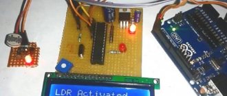
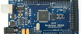
What is Arduino?
Arduino is a family of electronic platforms designed for learning electronics design.
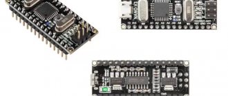
Arduino NANO is a compact microelectronic prototyping platform designed for use with a development board. The functionality of the device is in many ways similar to Arduino UNO and differs from it only in the size of the board and the absence of a separate connector for power.
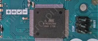
The basis of the Arduino Nano is a microcontroller based on ATmega328, a logical chip for data processing with a clock frequency of 16 MHz, which has 8 analog and 14 general-purpose digital pins on board, as well as all the necessary interfaces: I2C, SPI and UART.
Step-by-step instructions for connection
There are two methods to connect LED to Arduino:
- Through a breadboard.
- Through soldering of elements.
To work with a breadboard you will need:
- male-male wires;
- Light-emitting diode;
- 220 V resistor.
Connection instructions:
- The wire is connected at one end to the contact from which power will be supplied, and at the other end to the socket on the assembly field of the breadboard.
- A resistor is connected in series with the power supply to the breadboard socket (polarity is not important).
- An LED is connected in series with the resistor (anode to the resistor).
- The LED cathode is connected to the GND pin of the board.
Connection through soldering of elements is made in the same sequence with one exception: instead of male-male wires, conductors are used, the ends of which are tinned and soldered to the elements.
The advantage of the first method is simplicity, the disadvantage is weak contact between the elements. The advantage of the second connection method is reliable contact between the components; the disadvantage is the need to heat the board and elements with a soldering iron, which increases the risk of thermal breakdown of any component.
The LED on Arduino can blink without connecting peripherals. The board has a built-in LED that can be configured for any operating mode.
It is better to carry out all tests on a breadboard.
Board specifications
| Nutrition | 5 V |
| Input signal | 7-12 V (DC) |
| Number of DP | 14 (6 for PWM) |
| Number of APs | 8 |
| Maximum current DP | 40 mA |
| Flash format memory | 16 / 32 KB |
| RAM | 1 / 2 KB |
| EEPROM format memory | 512 bytes / 1 KB |
| Microcontroller clock frequency | 16 MHz |
| Dimensions | Width - 19 mm, length - 42 mm |
| Weight | 7 g |
A detailed overview of the board's capabilities is provided in the Datasheet - technical documentation. Detailed characteristics and description of AN are also indicated there.
Characteristics of Arduino Nano V2.3 ATmega168PA
| Microcontroller | ATmega168PA |
| Operating voltage | 5 V |
| Supply voltage (recommended) | 7-12 V |
| Supply voltage (limit) | 6-20 V |
| Digital inputs/outputs | 14 (6 of which can be used as PWM outputs) |
| Analog inputs | 8 |
| PWM (PWM) pins | 6 |
| DC current via input/output | 40 mA |
| Maximum pin output current 3.3V | 50 mA |
| Flash memory | 16 KB of which 2 KB are used by the bootloader |
| SRAM | 1 KB |
| EEPROM | 512 bytes |
| Clock frequency | 16 MHz |
| Built-in LED | 13 |
| Length | 42.0 mm |
| Width | 18.5 mm |
| Weight | 7 g |
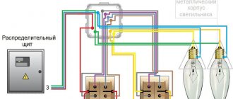
Schematic diagram
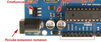
Module power supply
Arduino Nano can work from different power sources, it can be connected either through a Mini-B USB computer, or from a regular unregulated 6-20 volts (pin 30), or regulated 5 volts (pin 27). The board will automatically select the highest voltage supply.
- Via mini-USB or microUSB when connected to a computer;
- Through an external power source, voltage 6-20V.
External power is stabilized thanks to LM1117IMPX-5.0 with a voltage of 5V. When connecting via USB, a Schottky diode is used.
Arduino Nano board pinout
The figure shows the numbers and pin assignments of the Arduino Nano (view from the side on which the Atmega328 microcontroller is located):
Color interpretation:
– gray color – physical pin of the Atmega328 microcontroller;
– light gray color (PD0, PD1, etc.) – microcontroller port number, which is accessible from assembler programs;
– green color (ADC0, etc.) – numbers of analogue pins;
– blue color – pins of UART and SPI ports.
Purpose and pin designations:
USB is a USB port designed to connect the Arduino to a computer via a USB cable (a Mini-B USB connector is required).
VIN – power can be supplied here from an external 7-12 V power source (the power supply must be purchased separately). The voltage will be supplied to the stabilizer and dropped to 5 V. Therefore, it is optimal to supply about 9 V to this pin.
5V – through this pin you can also power the board from a 5 volt power source, but the voltage must be more or less stable, since it is supplied directly to the microcontroller (the stabilizer is not involved), and therefore high voltage can kill the main microcontroller.
3.3V – a voltage of 3.3 V will hang on this pin, which is generated from the board’s internal stabilizer. This pin is needed to connect some external devices that require 3.3 V to operate - usually these are all kinds of LCD displays. However, the maximum output current should not exceed 50 mA.
GND – ground (Ground Pin).
AREF – reference voltage for analog inputs. Used as needed (configured using analogReference()).
IOREF – allows you to find out the operating voltage of the microcontroller. Rarely used. It is completely absent on Chinese boards.
Reset – resets the microcontroller, apply a low level to this input.
SDA, SCL – TWI/I2C interface pins.
D0…D13 – digital inputs/outputs. There is a built-in LED hanging on pin D13, which lights up if the HIGH level is applied to pin D13.
0 (RX), 1 (TX) – pins of the UART port (Serial port).
A1…A5 – analog inputs (can also be used as digital).
Appearance of the Arduino Nano board with labeled pins:
Here:
RX+TX LEDs - LEDs blink when data is transmitted through the Serial UART serial port (RX and TX pins).
Reset Button – button to restart the microcontroller;
(see other designations above)
FTDI USB chip – FTDI FT323RL chip, which is used to connect the Arduino to a computer via a USB cable. From the Arduino side, this is a serial interface. This interface will be available on the computer as a virtual COM port (drivers for the FTDI chip must be installed - usually included in the Arduino IDE).
Schematically it looks like this:
Pin number, name, pin type and description:
GPIO
Let's start with the pins, which are the most numerous, these are GPIO, from English. General Purpose Input-Output, general purpose inputs and outputs, on the board they are labeled as D0–D13 and A0–A5. According to the pinout picture, they are called PD*, PB* and PC*, (instead of an asterisk - a number) are marked in dark beige. Why are they “officially” called PD/PB/PC? Because the pins are combined into several ports (no more than 8), in the Nano example there are three ports: D, B and C, respectively, the pins are labeled like this: PD3 – Port D 3 – the third output of port D. These are digital pins capable output a logic signal (0 or VCC) and read the same logic signal. VCC is the supply voltage of the microcontroller, in normal use of a regular Arduino board it is 5 Volts, accordingly this is 5 volt logic: 0V is a low level signal (LOW), 5V is a high level signal (HIGH). The supply voltage of the microcontroller plays a very important role, we will talk about this later. GPIOs have several operating modes: input (INPUT), output (OUTPUT) and input with a pull-up to the power supply by a 20 kOhm resistor built into the MK (INPUT_PULLUP). We'll talk more about modes in a separate lesson.
All GPIO pins in input mode can accept a signal with a voltage from 0 to 5 volts (actually up to 5.5 volts, according to the microcontroller datasheet). Negative voltage or voltage exceeding 5.5 Volts will lead to failure of the pin or even the MK itself. A voltage of 0-2.5 volts is considered low level (LOW), 2.5-5.5 is considered high level (HIGH). If the GPIO is not connected anywhere, i.e. “hangs in the air”, it receives random voltage arising from interference from the network (220V wires in the walls) and electromagnetic waves at different frequencies that permeate the modern world.
GPIO in output mode (OUTPUT) are transistor outputs of the microcontroller and can output voltage 0 or VCC (MCU supply voltage). It is worth noting that the microcontroller is a logical, not a power device; its outputs are designed to send signals to other pieces of hardware, and not to directly power them. The maximum current that can be removed from the GPIO output of the Arduino is 40 mA. If you try to remove more, the pin will fail (the output transistor will burn out and that’s it). What is 40 mA? A regular 5mm single-color LED consumes 20 mA, and this is practically the only thing that can be powered directly from the Arduino. Also, do not forget about the maximum current from all pins, it is limited to 200 mA, that is, no more than 10 LEDs can be powered from the board at full brightness...
Interfaces
Most GPIOs have additional capabilities, since pins from other microcontroller systems are connected to them, you are already familiar with them from the previous lesson:
- ADC (ADC, analog-to-digital converter) – green ADC* signatures on the pinout
- UART (communication interface) – blue TXD and RXD on pinout
- Timer outputs, also known as PWM pins, are light purple OC*A and OC*B, where * is the timer number
- SPI (communication interface) – blue SS, MOSI, MISO, SCK
- I2C (communication interface) – blue SDA and SCL
- INT (hardware interrupts) – pink INT0 and INT1, as well as PCINT* – PinChangeInterrupt
ADC
ADC pins (with ADC) are marked on the board with the letter A. Yes, pins A6 and A7 on the Nano board have only an ADC input and are not GPIO pins! ADC is an analog-to-digital converter that allows you to measure voltage from 0 to VCC (MK supply voltage) or reference voltage. On most Arduino boards, the ADC capacity is 10 bits (2^10 = 1024), which means the following: the voltage from 0 to the reference is converted into a digital value from 0 to 1023 (1024-1 since the count starts from zero). The reference voltage plays a very important role: with a reference voltage of 5V, one ADC measurement step will be 4.9 millivolts (0.00488 V), and with a reference voltage of 1.1V – 1.1 mV (0.00107 V). The whole point is exactly, I think you understand. If the reference voltage is set below the supply voltage of the MK, then by digitizing a voltage above the reference we will get 1023. By applying a voltage higher than 5.5 Volts to the ADC we will get a burnt-out port. Applying negative voltage is also not recommended. The Arduino has several reference voltage modes: it can be equal to VCC (supply voltage), 1.1V (from the stabilizer built into the MK) or receive a value from an external source in the Aref pin, this way you can adjust the desired range and obtain the required accuracy. Other Arduino models (for example Mega) have other built-in modes. It is recommended to connect the reference voltage to the board through a resistor, for example 1 kOhm. To measure voltages above 5.5 volts, you must use a voltage divider across resistors.
Timers (PWM)
Timer outputs: in the microcontroller, in addition to the regular computing core with which we work, there are also “hardware” counters that work in parallel with all the other hardware. These counters are also called timers, although they have nothing to do with timers: counters literally count the number of ticks made by the crystal oscillator, which sets the operating frequency for the entire system. Knowing the frequency of the oscillator (usually 16 MHz) you can determine time intervals with very high accuracy and do something based on this. What use are these meters to us? Out of the box, called Arduino IDE, we have several ready-made timer-based tools (time functions, delays, pulse length measurements, and others).
This article is about pins and outputs, so we’ll talk about them: each counter has two GPIO outputs. The nano (ATmega328p MK) has three counters, respectively, 6 outputs. One of the counters' capabilities is the generation of a PWM signal, which is output to the corresponding GPIOs. For nano these are D pins 5 and 6 (counter 0), 9 and 10 (timer 1) and 3 and 11 (timer 2). A separate lesson is devoted to the PWM signal, now let’s just remember that with its help you can control the brightness of LEDs, the rotation speed of motors, the heating power of the coils and much more. But you need to remember that the current limit of 40 mA has not gone away and nothing more powerful than LEDs cannot be powered from the pins.
Interrupts
Hardware interrupts allow the processor to instantly switch to a certain block of actions (interrupt handler function) when the signal level on the pin changes. We'll talk more about this, as well as about PinChangeInterrupts, in another lesson.
Other pins
- The 3.3V pin can be used to power low-power sensors and modules: the maximum current that can be removed from the 3.3V pin is 150 mA, which is enough for any sensors and modules, except perhaps the nrf25L01 radio modules.
- GND pins – power ground, all GNDs are interconnected
- Pin 5V – power supply from a source with a voltage of up to 5.5V (for more details about power supply, see the next lesson)
- Pin Vin – power from a source with a voltage of 7-15V (for more details about power supply, see the next lesson)
- RST – MK reboot. This pin is also displayed on the button
Conventional LEDs
An LED is the simplest indicator that can be used to debug code: it can be turned on when a condition is triggered or simply wink. But first you need to connect it.
LED connection
An LED is a device that is powered by current, not voltage. What does it mean? The brightness of an LED depends on the current that passes through it. It would seem that knowledge of Ohm's law from the first lesson in the section is enough, but this is not so!
- The LED in the circuit cannot be replaced with a “resistor”, because it behaves differently, nonlinearly.
- The LED is polarized, that is, if it is connected incorrectly, it will not light up.
- The LED has a maximum current characteristic that it can operate at. For regular 3 and 5mm LEDs this is typically 20mA.
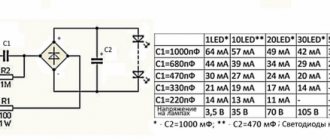
- The LED has a voltage drop characteristic (Forward Voltage), the magnitude of this drop depends on the emitted color. The color is emitted by the crystal, the composition of which determines the color. For red LEDs the drop is ~2.5 volts, for blue, green and white LEDs ~3.5 volts. More accurate information can be found in the documentation for the specific LED. If there is no documentation, you can use this plate, here are the minimum values:
If you power the LED with a voltage below its drop voltage, then the brightness will not be maximum, and no drivers are needed here. That is, the red LED can be powered from a AA battery without any problems. At the same time, the crystal may degrade and the voltage will decrease, which will lead to an increase in current. But this is a rare case. As soon as we exceed the drop voltage, we need to stabilize the power supply, namely the current. In the simplest case, a resistor is installed for a conventional LED, the value of which must be calculated using the formula: R = (Vcc - Vdo) / I, where Vcc is the supply voltage, Vdo is the drop voltage (depending on the LED), I is the LED current, and R is the desired resistance of the resistor. Let's calculate the resistor for a regular 5 mm red LED when powered by 5 Volts at maximum brightness (2.5 V, 20 mA): (5-2.5)/0.02=125 Ohm. For blue and green colors you get 75 ohms. The brightness of an LED depends nonlinearly on current, so “by eye” at 10 mA the brightness will be the same as at 20 mA, and the resistance value can be increased. But you can’t reduce it, just as you can’t connect it without a resistor at all. In most tutorials and projects in general, a 220 ohm resistor is used for regular LEDs of all colors. With a 1 kOhm resistor, the LED will also glow, but noticeably dimmer. Thus, using a resistor, you can set the brightness of the LED in hardware. How to determine the plus ( anode ) and minus ( cathode ) of an LED? The plus leg is longer, the side of the minus leg is slightly cut off, and the electrode itself inside the LED is larger:
Flashing
Flashing an LED with Arduino is very simple: connect the cathode to GND, and the anode to the GPIO pin. Many people are sure that “analog” pins are just analog, but this is not the case: these are ordinary digital pins with the ability to digitize an analog signal. On the Nano board, pins A0-A5 are digital and analog at the same time, but A6 and A7 are analog, that is, they can only read an analog signal. So let's connect to A1, configure the pin as an output and flash!
void setup() { pinMode(A1, OUTPUT); } void loop() { digitalWrite(A1, HIGH); delay(500); digitalWrite(A1, LOW); delay(500); }
I talked about how to get rid of delay() in any code in this lesson. https://www.youtube.com/watch?v=uaiLcCd9Tnk
Flashing smoothly
How about smooth brightness control? Let's remember the lesson about the PWM signal and connect the LED to one of the PWM pins (on Nano these are D3, D5, D6, D9, D10, D11). Let's make a pin as an output and we can control the brightness using a PWM signal! Read the lesson about PWM signal. A simple example with several brightness levels:
void setup() { pinMode(3, OUTPUT); } void loop() { analogWrite(3, 10); delay(500); analogWrite(3, 100); delay(500); analogWrite(3, 150); delay(500); analogWrite(3, 200); delay(500); analogWrite(3, 255); delay(500); }
Let's connect a potentiometer to A0 and try to adjust the brightness with it:
void setup() { pinMode(3, OUTPUT); } void loop() { // analogRead(0) / 4 == 0... 255 analogWrite(3, analogRead(0) / 4); delay(100); }
As you can see, everything is very simple. Let's do one more interesting thing: let's try to smoothly turn on and off the LED, for which we will need a loop from the lesson about loops.
void setup() { pinMode(3, OUTPUT); } void loop() { for (int i = 0; i < 255; i++) { analogWrite(3, i); delay(20); } for (int i = 255; i > 0; i—) { analogWrite(3, i); delay(20); } }
Bad example! The smooth brightness change algorithm blocks code execution. Let's do it on an uptime timer.
void setup() { pinMode(3, OUTPUT); } uint32_t tmr; int val = 0; bool dir = true; void loop() { if (millis() - tmr >= 20) { tmr = millis(); if (dir) val++; // increase the brightness else val—; // decrease if (val >= 255 || val <= 0) dir = !dir; // expand analogWrite(3, val); } }
Now changing the brightness does not block the execution of the main loop, but the rest of the code should be written in the same way so as not to block calls to the brightness change function! Another option could be to interrupt the timer, see the lesson.
The LED will not blink very smoothly: the brightness will increase too sharply and will hardly change. This is due to the fact that the human eye perceives brightness nonlinearly, but we control it linearly. For a smoother feeling of brightness, correction according to the CRT gamma is used, which has been moved from this lesson to a separate lesson on blinking an LED according to the CRT gamma in the algorithms block. Be sure to study it!
One more point: if you connect the LED the other way around, to VCC, its brightness will be inverted: 255 will turn off the LED, and 0 will turn it on, because the current will flow in the other direction:
Communication Interfaces
Arduino Nano supports I2C interface for communication with various devices and peripherals. One common application is communicating with a display via the I2C bus. Thanks to special technology, you can display sets of characters and data on the display using only 2 pins, in Nano these are pins D4 SDA) and D5 (SCL).
The official website has a special library for working with it. When writing programs, do not forget to include it with the directive:
#include SPI.h
Now you can organize a communication system.
Schematic diagram of the Arduino Nano board
Part of the circuit near the Atmega328P microcontroller:
Part of the circuit near the FT323 chip (but on Chinese boards it will be replaced by CH340):
Power stabilizer:
ISCP connector diagram (more details here):
Schematic of the entire Arduino Nano board:
Firmware and memory Arduino v3 0 CH340G
The standard version of the Arduino Nano board, running on the ATmega328P chip, can be flashed exclusively through a programmer with an SPI interface.
In addition, the AN model is produced, on which the CH340G chip is additionally installed. The advantage of this assembly is that the board can be flashed without connecting an SPI programmer via a USB port. This can be done with the built-in bootloader and USB-COM converter.
If necessary, such a Nano model can also be flashed via the SPI interface.
To download firmware via mini-USB, you will need:
- Connect the board to the PC via USB. The system will detect the device as USB 2.0 SERIAL.
- Download and install the CH340G driver.
As soon as the driver is installed, the system will detect the board correctly and it can be flashed through the programmer. The ON LED on the board will light up and the LED will blink.
Types of memory
ATmega328P supports 3 types of memory:
- Flash. It acts as a permanent storage device.
- RAM.
- EEPROM This memory is also a read-only memory, but it can be reprogrammed.
The microcontroller from Atmel has 32 KB of Flash memory (30 KB free, since 2 KB is occupied by the bootloader), 2 KB of RAM and 1 KB of EEPROM.
What you need to connect LED to Arduino board
There are two options for connecting the LED. For learning purposes, you can choose any one.
- Use built-in LED. In this case, you will not need anything more than a cable to connect to a PC via a USB connector for power and programming. There is no point in using an external voltage source to power the board: the current consumption is small.
USB AB cable for connecting Arduino Uno to PC. - Connect external LEDs. Here you will additionally need:
- the LED itself;
- current-limiting resistor with a power of 0.25 W (or more) with a nominal value of 250-1000 Ohms (depending on the LED);
- wires and a soldering iron for connecting an external circuit.
Connecting an external LED directly to the controller output.
LEDs are connected with the cathode to any digital pin of the microcontroller, and the anode to the common wire through a ballast resistor. If there are a large number of LEDs, an additional power source may be needed.
Board elements
Arduino Nano consists of many elements, including:
- microcircuits;
- passive elements (resistors, capacitors, diodes);
- connectors;
- regulators.
FT232R board chip
The chip allows you to connect the board via USB. The chip installed in the AN cannot work directly with the USB interface, so the FT232R converts it to a UART interface.
The heart of the platform is the ATmega328P microcontroller
ATmega328P is the main control element of the board. A sketch written by the programmer is loaded into it, and the controller sends commands to various elements of the board. For example, a microcontroller causes diodes to blink, relays to switch, and a piezoelectric element to make sounds.
LED indication
There are 4 LEDs built into the board, each of which has its own purpose:
- The RX and TX LEDs blink when data is being transferred via the UART.
- The L-diode lights up when a high signal level is applied to it, and turns off when the signal level is low.
- The ON LED lights up when there is power on the board.
Additionally, almost any pin of the microcontroller can be connected to other LEDs, 7-segment indicators or even displays.
Mini-USB connector
Using the mini-USB connector, the board can be connected to a personal computer. The AN can also receive power from external sources through this interface.
Linear Buck Voltage Regulator 5V
The LM1117MPX-5.0 microcircuit is used as a regulator. It converts the AN power signal into a power signal for the ATmega microcontroller and other logic elements that do not support power supplies greater than 5 V. For example, transistor-transistor logic (TTL) elements are powered by a signal of this magnitude.
Description of pins and pinout of Arduino Nano board
The figure shows the numbers and pin assignments of the Arduino Nano (view from the side on which the Atmega328 microcontroller is located):
Each of the Nano's 14 digital pins can be configured as an input or output using the pinMode(), digitalWrite(), and digitalRead() functions. The pins operate at 5 V. Each pin has a 20-50 kOhm load resistor and can carry up to 40 mA. Some pins have special functions:
- Serial bus: 0 (RX) and 1 (TX). The pins are used to receive (RX) and transmit (TX) TTL data. These pins are connected to the corresponding pins of the FTDI USB-to-TTL serial bus chip.
- External Interrupt: 2 and 3. These pins can be configured to trigger an interrupt on either a low value, a rising or falling edge, or a value change. See the attachInterrupt() function for details.
- PWM: 3, 5, 6, 9, 10, and 11. Either pin provides 8-bit PWM using the analogWrite() function.
- SPI: 10 (SS), 11 (MOSI), 12 (MISO), 13 (SCK). These pins provide SPI communication, which, although supported by the hardware, is not included in the Arduino language.
- LED: 13. Built-in LED connected to digital pin 13. If the pin value is high, the LED is lit.
The Nano platform has 8 analog inputs, each with a resolution of 10 bits (i.e., can take 1024 different values). By default, the pins have a measurement range of up to 5 V relative to ground, however it is possible to change the upper limit using the analogReference() function. Some pins have additional functions:
- I2C: A4 (SDA) and A5 (SCL). The pins provide I2C (TWI) communication. The Wire library is used for creation.
Additional pair of platform pins:
- AREF. Reference voltage for analog inputs. Used with the analogReference() function.
- Reset. A low signal on the pin resets the microcontroller. Typically used to connect a reset button on an expansion board, which blocks access to the button on the Arduino board itself.
Color interpretation
– gray color – physical pin of the Atmega328 microcontroller;
– light gray color (PD0, PD1, etc.) – microcontroller port number, which is accessible from assembler programs;
– green color (ADC0, etc.) – numbers of analogue pins;
– blue color – pins of UART and SPI ports.
Purpose and pin designations
USB is a USB port designed to connect the Arduino to a computer via a USB cable (a Mini-B USB connector is required).
VIN – power can be supplied here from an external 7-12 V power source (the power supply must be purchased separately). The voltage will be supplied to the stabilizer and dropped to 5 V. Therefore, it is optimal to supply about 9 V to this pin.
5V – through this pin you can also power the board from a 5 volt power source, but the voltage must be more or less stable, since it is supplied directly to the microcontroller (the stabilizer is not involved), and therefore high voltage can kill the main microcontroller.
3.3V – a voltage of 3.3 V will hang on this pin, which is generated from the board’s internal stabilizer. This pin is needed to connect some external devices that require 3.3 V to operate - usually these are all kinds of LCD displays. However, the maximum output current should not exceed 50 mA.
GND – ground (Ground Pin).
AREF – reference voltage for analog inputs. Used as needed (configurable using analogReference).
IOREF – allows you to find out the operating voltage of the microcontroller. Rarely used. It is completely absent on Chinese boards.
Reset – resets the microcontroller, apply a low level to this input.
SDA, SCL – TWI/I2C interface pins.
D0…D13 – digital inputs/outputs. There is a built-in LED hanging on pin D13, which lights up if the HIGH level is applied to pin D13.
0 (RX), 1 (TX) – pins of the UART port (Serial port).
A1…A5 – analog inputs (can also be used as digital).
Appearance of the Arduino Nano board with labeled pins
Here:
RX+TX LEDs - LEDs blink when data is transmitted through the Serial UART serial port (RX and TX pins).
Reset Button – button to restart the microcontroller;
(see other designations above)
FTDI USB chip – FTDI FT323RL chip, which is used to connect the Arduino to a computer via a USB cable. From the Arduino side, this is a serial interface. This interface will be available on the computer as a virtual COM port (drivers for the FTDI chip must be installed - usually included in the Arduino IDE).
It will be interesting➡ The most popular Arduino projects
Schematically it looks like this:
Pin number, name, pin type and description:
Guide for Arduino Beginners
1. Install Arduino IDE and drivers as written in the guide. If this is your first time, it is advisable not to connect anything to the new board, but to download the trial firmware from the guide and make sure that everything loads and works. If, after assembling the circuit, the firmware stops loading, alas, the circuit was assembled with errors and the board could already burn out. But it worked, we checked it =)
- If the project is based on esp8266 or Digispark , we install support for these boards, as described in the guide above.
2. Download the archive from the project page . There is always one link, it leads to a direct download of the archive from the GitHub repository. When the project is updated (this may be written on the project page), the link to the archive remains the same, but it will already contain some changed files, new firmware versions have been added, etc. All updates are indicated on the project page.
3. Unpack the archive . The archive is in .zip format; to unpack it, you can use the built-in tools of the operating system, or the popular WinRAR. If you do not unpack the archive, the firmware will not open correctly. I don’t have a wild imagination and always name folders the same, here’s what might be in the project archive:
- firmware – firmware for Arduino
- software – programs for PC
- libraries – libraries
- schemes - schemes
- PCB – gerber files of printed circuit boards
- docs – all kinds of documents
- Android - application sources
- 3Dprint – models for printing
- processing – a program based on Processing
WinRAR Extraction
Extract Windows Unpacked folder
4. Install libraries . The firmware of my projects always comes with the libraries necessary for the code to work. Libraries in projects often overlap, but it is recommended to install the version that comes with the project, since older or newer ones may be incompatible.
libraries folder from the archive are placed in
- C/Program Files/Arduino/libraries/ (Windows x32)
- C/Program Files (x86)/Arduino/libraries/ (Windows x64)
Installation in libraries
If you have problems accessing this folder (on Windows 10), you can put the libraries in
- Documents/Arduino/libraries/
Installation in documents
Note : different projects have different versions of the same libraries; they are not always compatible. If errors occur, it is recommended to delete the current versions and replace them with those included in the archive.
5. Open the sketch (this is the name of the file with the program). When you run the sketch file, the Arduino IDE will automatically open. Important : if there are several files in the folder with the sketch, run any one with the Arduino logo. The remaining files should be pulled up automatically and form tabs in the program window. If you run the sketch directly from the archive, the tabs will not open and it will be impossible to compile/download the program.
Tabs in Arduino IDE
6. Select board and port . In the program settings, select the appropriate board and the port where it is connected, as in the guide above. Important points regarding the settings of the board itself are usually indicated in the description of a specific project.
- Arduino Nano projects, select Arduino Nano, as well as Tools\Processor\ATmega328p (Old Bootloader). If for some reason they send you boards with a new bootloader - the firmware will not load (there will be a minute loading and an error), you can try changing the Processor item to ATmega328p
- For projects on Wemos , select (LOLIN)Wemos D1 R2 & mini
- For projects on NodeMCU , select NodeMCU 1.0
- In some projects, for example GyverLamp2 (second version) for firmware in esp8266 you need to select the Generic esp8266 board, read the download details on the project page!
- For projects on Digispark you do not need to select a port, read the instructions above
7. Set up the program . Very often at the beginning of the code of my programs you can find a settings block. The settings usually look like
#define SOME_SETTING 1 // 1 enabled, 0 disabled
where the number is responsible for the setting value, you only need to change the number according to the comment.
8. Download firmware . Click the arrow in the upper left corner of the program window and the firmware is loaded. Is not downloading? Read the guide above, all possible reasons are described there.
It is advisable to download the firmware before connecting the components to make sure that the board is working. After assembly, you can flash it again, the board should be flashed smoothly. In projects with powerful consumers in the board's 5V power supply circuit (addressable LED strip, servos, motors, etc.), it is necessary to supply external 5V power to the circuit before connecting the Arduino to the computer, because USB will not provide the required current if the consumer requires it - this may cause the protective diode on the Arduino board to burn out.
9. If something doesn’t work , read the instructions, it describes every step and the solution to all problems. There is also a video at the very beginning where everything is shown in even more detail.
A note for those who did not read the instructions and received some kind of error. Here is a list of the most common reasons:
- I did not unpack the archive and ran the sketch directly from it, but received a compilation error in the style of not declared in this scope. UNPACK THE ARCHIVE
- The error log contains the phrase no such file or directory – the libraries were not installed. INSTALL LIBRARIES
- A download error occurs. RETURN TO IDE SETUP INSTRUCTIONS
- Something on the board is heating up and the firmware is not loading. I MADE AN ERROR WHEN ASSEMBLYING, EVERYTHING BURNED
- I installed an old or crooked version of the Arduino IDE and received strange errors - uninstall the old one and INSTALL THE FRESH VERSION
Description of Arduino Nano V3 board elements
- USB Jack – USB Mini-B connector for connecting USB devices;
- Analog Reference Pin – to determine the ADC reference voltage;
- Ground - earth;
- Digital Pins (2-13) – digital pins;
- TXD – data transfer pin via UART;
- RXD – data reception pin via UART;
- Reset Button – button to reset the microcontroller;
- ISCP (In-Circuit Serial Programmer) – contacts for reprogramming the board;
- Microcontroller ATmega328P – microcontroller - the main element on the board;
- Analog Input Pins (A0-A7) – analog inputs;
- Vin – input is used to supply power from an external source;
- Ground Pins - ground;
- 5 Volt Power Pin – 5 V power supply;
- 3 Volt Power Pin – power supply 3.3 V;
- RST – input for reboot;
- SMD Crystal - quartz resonator (jarg "quartz") - a device in which the piezoelectric effect and the phenomenon of mechanical resonance are used to construct a high-quality resonant element of an electronic circuit;
- TX LED (White) – LED – indicator of data sending via UART;
- RX LED (Red) – LED – indicator of data reception via UART;
- Power LED (Blue) – LED – power indicator;
- Pin 13 LED (Wellow) – connected LED to the 13th pin.
Pin description/Arduino Nano pinout
Each of the Nano's 14 digital pins can be configured as an input or output using the pinMode(), digitalWrite(), and digitalRead() functions. The pins operate at 5 V. Each pin has a 20-50 kOhm load resistor and can carry up to 40 mA. Some pins have special functions:
- Serial bus: 0 (RX) and 1 (TX). The pins are used to receive (RX) and transmit (TX) TTL data. These pins are connected to the corresponding pins of the FTDI USB-to-TTL serial bus chip.
- External Interrupt: 2 and 3. These pins can be configured to trigger an interrupt on either a low value, a rising or falling edge, or a value change. See the attachInterrupt() function for details.
- PWM: 3, 5, 6, 9, 10, and 11. Either pin provides 8-bit PWM using the analogWrite() function.
- SPI: 10 (SS), 11 (MOSI), 12 (MISO), 13 (SCK). These pins provide SPI communication, which, although supported by the hardware, is not included in the Arduino language.
- LED: 13. Built-in LED connected to digital pin 13. If the pin value is high, the LED is lit.
The Nano platform has 8 analog inputs, each with a resolution of 10 bits (i.e., can take 1024 different values). By default, the pins have a measurement range of up to 5 V relative to ground, however it is possible to change the upper limit using the analogReference() function. Some pins have additional functions:
- I2C: A4 (SDA) and A5 (SCL). The pins provide I2C (TWI) communication. The Wire library is used for creation.
Additional pair of platform pins:
- AREF. Reference voltage for analog inputs. Used with the analogReference() function.
- Reset. A low signal on the pin resets the microcontroller. Typically used to connect a reset button on an expansion board, which blocks access to the button on the Arduino board itself.
Changing the LED flashing frequency
To make the LED blink faster, you need to change the parameter specified in parentheses ( ) in the “delay” command.
As already stated, the delay period is specified in milliseconds. That is, in order to make the LED blink twice as often, you need to change the value from 1000 to 500. As a result, the pause between turning the LED on/off will be half a second and the LED will blink faster.
To check, do not forget to upload the modified sketch to the Arduino board.
Connecting Arduino Nano
Connecting the Arduino Nano board to a computer is not particularly difficult - it is similar to a regular Uno board. The only difficulty may arise when working with a board based on the ATMEGA 168 chip - in the settings you need to first select the Nano board, and then the desired processor option.
Installing the driver for CH340
The CH340 chip is often used in Arduino boards with a built-in USB-to-Serial converter. It allows you to reduce the cost of producing boards without affecting its performance. With this programmer you can easily flash Arduino boards. In order to start working with this chip, you need to install the driver on your computer.
The installation is carried out in several stages:
- Downloading an archive with a driver for the desired operating system. For Windows, MacOS and Linux, you can download drivers from the link in our article about USB UART.
- Unpacking the archive.
- Search for the SETUP.EXE file and launch it.
- A window will appear on the monitor in which you need to click the Install button. The driver installation will begin, after which you can start working with the circuit.
Arduino IDE setup
The standard Arduino IDE development environment is used to work all types of Arduino with a computer. To get started, you must first download the Arduino IDE from the official website and install it. It is more convenient to download Windows Installer, especially if the development environment will be installed on a permanent working computer. If you downloaded the archive, you need to unpack it and run the Arduino.exe file.
Once the environment is installed, you need to run it. To do this, you need to connect the Arduino board itself to the computer via USB. Then go to the Start menu >> Control Panel >> Device Manager, find COM and LPT ports there. The installed board will appear in the list and the port number to which the board is connected will be indicated.
After this, you need to launch the Arduino IDE, go to the Tools >> Port menu, and specify the port to which the Arduino is connected. In Tools >> Boards you need to select the model of the connected board, in this case Arduino Nano. If you have a Nano board version 2.0, then you also need to select the processor option in the corresponding menu.
It is important to remember that if another board is connected to the computer, the settings will again need to be changed to the corresponding device.
Setting up Arduino IDE
Launch Arduino IDE, select the board (Toolsboard”your board”). See first screenshot.
Select the microcontroller model (ToolsProcessor”Your processor”). Arduino NANO can have atmega328p or 168, I always leave links to 328p (168 - less memory, more problems).
ATTENTION! The microcontroller on the board you purchased can be flashed with a “new” or “old” bootloader; both are available for sale. Starting with Arduino IDE version higher than 1.8.4, you can choose ATmega328P and ATmega328P (Old Bootloader) , try both, because this is determined by random method.
Select port: toolsport”COM other than COM1, for example COM3, COM5...” See second screenshot. Which port did you see when you first connected the Arduino to the computer? Note: if you only have COM1, it means either the drivers are not installed or the board is dead.
Ready-made firmware simply opens with a double click. To download the firmware, click the DOWNLOAD button on the top toolbar, it is in the form of an arrow.
ATTENTION ! There should be no Russian letters in the path to the folder with downloaded sketches! Create an Arduino folder in the root of the disk and work in it!
ATTENTION! As soon as you take the Arduino out of the bag, immediately flash a sketch into it with a blinking LED (blink.ino) . This way you will know that the Arduino is working (in case after assembly/soldering it stops working and flashing), that is, you yourself they broke it, but it was not originally defective
Example projects with Arduino Nano
It is convenient to implement projects on AN due to the presence of libraries that simplify writing code.
Connecting LEDs to Arduino Nano
You can power the LED diode, for example, using pin 13 through a 220 Ohm limiting resistor. To blink this diode, you should write the following code:
| 1 2 3 4 5 6 7 8 9 10 | void setup(){// initialization of code elements (analogous to int main() in C) pinMode(13, OUTPUT);// declaring pin 13 as an output} void loop(){// infinite loop (analogous to while (1) in C) digitalWrite(13, HIGH);// turn on the LED delay(1000);// ensure blinking with a frequency of 1 Hz digitalWrite(13, LOW);// turn off the LED delay(1000);// ensure blinking with a frequency of 1 Hz} |
void setup() { // initialization of code elements (analogous to int main() in C) pinMode(13, OUTPUT); // declare pin 13 as an output } void loop() { // infinite loop (analogous to while (1) in C) digitalWrite(13, HIGH); // turn on the LED delay(1000); // ensure blinking at a frequency of 1 Hz digitalWrite(13, LOW); // turn off the LED delay(1000); // ensure blinking at a frequency of 1 Hz }
To create a pixel image, where a pixel is 1 diode, the WS2812 address strip is used.
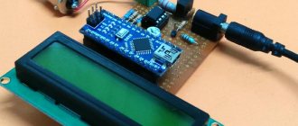
Connecting LCD 1602 to Arduino Nano
The LCD 1602 is a monochrome programmable display. To connect it to the board you need to write the following sketch:
| 1 2 3 4 5 6 7 8 9 10 11 12 | #include
|
#include
- LiquidCrystal lcd(12, 11, 5, 4, 3, 2); void setup(){ lcd.init(); // initializing the screen lcd.backlight(); // activate the backlight lcd.setCursor(0,0); // placing the cursor at the beginning of the first line lcd.print(“text”); // typing text on the first line lcd.setCursor(0,1); // placing the cursor at the beginning of the second line lcd.print(“text”); // typing text on the second line }
Connecting NRF24L01 to Arduino Nano
NRF24L01 is a radio module that is often used to create the Internet of Things. It is installed on the board as follows:
Module pin Pinout boards GND GND VCC 3.3 V C.E. D9 CSN D10 SCK D13 MOSI D11 MISO D12 IRQ Doesn't connect
Arduino Nano ISCP Circuit
Finally, we must say about connecting the programmer. To program the Atmel controllers on which the Arduino module is assembled, the ICSP interface is used. For Arduino Nano icsp the pinout looks like this (see top of previous picture):
- MISO (master receives from slave);
- SCK (clock pulse);
- MOSI (master transmits to slave);
- RESET (reset);
- GND (ground).
+5V (power);
The first pin of the 6-pin connector has a square shape at the base and is numbered clockwise when viewed from above. To avoid any doubt regarding the numbering order of the connector pins, below is a fragment of the Arduino board circuit diagram:
This connector connects to a programmer with an SPI (Atmel Serial Programming Interface) interface. In addition, the controller firmware can be changed from the programming environment via a USB cable, so purchasing a programmer becomes optional (it is only needed if there is no bootloader program).
ICSP pinout
ICSP (In Circuit Serial Programming) is one of several methods available for programming Arduino boards. Typically the Arduino bootloader program is used to program the Arduino board, but if the bootloader is missing or damaged, the ICSP can be used instead. ICSP can be used to repair a missing or damaged bootloader.
Arduino nano icsp pinout
Each ICSP pin is usually connected to another Arduino pin with the same name or function. For example, MISO in ICSP Nano is connected to MISO/digital pin D12, MOSI in ISCP is connected to MOSI/digital pin D11, and so on.
Module power supply
Arduino Nano can work from different power sources, it can be connected either through a Mini-B USB computer, or from a regular unregulated 6-20 volts (pin 30), or regulated 5 volts (pin 27). The board will automatically select the highest voltage supply.
- Via mini-USB or microUSB when connected to a computer;
- Through an external power source, voltage 6-20V.
External power is stabilized thanks to LM1117IMPX-5.0 with a voltage of 5V. When connecting via USB, a Schottky diode is used.
Installing drivers
On Windows, the drivers will be installed automatically when you connect the board if you used the installer. If you downloaded and extracted the Zip archive or for some reason the board is not recognized correctly, follow the procedure below.