Scope of application of two-color LEDs
A 2-color LED is an integrated assembly with two light-emitting crystals on one substrate. Despite the rather limited emission spectrum, 2-color LEDs are widely used in:
- instrument making, as a two-color 5mm LED used as an indicator;
- advertising business to attract consumer attention;
- decorating rooms using the play of light;
- modern signaling equipment, such as a two-color LED flasher, traffic lights;
- car tuning;
These devices are widely used in alarm, indication and visual design systems. 2-color LED lighting is actively used in the creation of electronic displays and signs. In addition, a two-color LED is used as a rotation indicator for a DC motor, showing which direction it is rotating.
LED for 2 colors – these are two ordinary LEDs in one housing. It has two legs and each is simultaneously the cathode of an LED of one color and the anode of a different color. Therefore, the color of the lamps will depend on the direction in which the current flows through the two-color diode. This LED requires only one resistor. Two-color LEDs are less popular than three-color LEDs. An example of a 2-color LED is charging for a mobile device and a battery, when the indicator light glows red during charging, and after charging the battery the light changes to green.
In cars, LED lamps are used where 2 colors are required in the headlight, when one lamp simultaneously serves as a marker and a turn signal. The dimensions will be red, and the turn signals will be yellow.
How to connect a two-color LED?
Connecting LEDs to a circuit requires connecting a ballast resistor, which is built into modern LEDs. By limiting the current in the circuit, connecting the LED is possible with a network voltage of 220V.
Connection diagrams for two-color LEDs
To make an electrical appliance with your own hands, you need to know how to connect a two-light LED. The simplest (but not entirely correct) option is to connect power to the legs through a resistor and determine the on/off cycles.
To add a resistor to the circuit, you need to calculate its resistance and power values.
Since 2015, GOST 29433-2014 has defined new power supply voltage parameters:
- nominal 230 V;
- minimum 207 V, under load 198 V;
- maximum 253 V.
The resistance of the resistor must be of such a value that the current necessary for the normal functioning of the two-color LED can flow through it, but the element does not overheat. Therefore, the rated current value of 20 mA for calculations is replaced by another value - 7 mA = 0.007 A, which allows the diode to glow normally.
Resistance:
You need to buy a 33 kOhm element.
Resistor power:
You need to buy a 2 W element.
To check, the current at maximum voltage is calculated:
Power:
This means that a 2 W resistor will not overheat even at the maximum network voltage.
On timer 555
The 555 timer is an integrated device that generates pulses at certain intervals. Models are available in plastic and metal DIP and SMD housings for 4.5 – 16 V. The main area of application in everyday life is the control of three-color strips and lamps. Timer 555 turns on the colors one by one. The standard supply voltage is 5 V, you can convert it to 12 V by changing the resistance of the resistors.
A similar circuit with a 555 timer can be created to control a two-color LED. It is necessary to power the circuit from a 220 V network through a step-down transformer. The voltage is stabilized by the 7805 regulator. The transformer can have one or more windings. The second option requires an additional output from the 12 V winding.
If the LED is multicolor, the circuit includes as many timers as there are colors. The colored elements are connected to the 555 pins via resistors. As the resistance changes, the glow intensity changes from minimum to maximum value.
Up to 1a
To drive two-color LEDs operating at currents up to 1 A, a TA7291P circuit is used, equipped with two inputs and outputs. A two-color LED is connected to the output. If the logic of the diodes, transistors and relays is the same, but the outputs are different, the chip does not light up.
With the same logic levels, the circuit works differently. If the levels at the inputs are different, one of the outputs is connected to a common wiring, which leads to the cathode of a two-color diode and a resistor being connected to it. The voltage at the second output changes simultaneously with the voltage at the input. This makes it possible to adjust the intensity of the glow.
The voltage at the second output is supplied from the microcontroller that produces pulses. In addition to the brightness of the glow, the microcontroller controls the inputs, so it is possible to regulate the control algorithm and shades of the glow.
control circuit for two-color LEDs up to 1A
The control circuit for two-color LEDs is based on a TA7291P chip with two OUT outputs and two IN inputs. We connect two diodes or one two-color diode with a power of at least 1A to the output. If the logic at the inputs is the same, then the output potentials are equal, and accordingly the LED does not light up.
At different logical levels at the inputs, the microcircuit operates as follows. If one of the inputs, for example, IN1, has a low logical level, then the output OUT1 is connected to the common wire. The cathode of LED HL2 is also connected to the common wire through resistor R2. The voltage at the OUT2 output (if there is a logical one at the IN2 input) in this case depends on the voltage at the V_ref input, which allows you to adjust the brightness of the HL2 LED.
In this case, the voltage V_ref is obtained from PWM pulses from the microcontroller using the integrating chain R1C1, which regulates the brightness of the LED connected to the output. The microcontroller also controls the inputs IN1 and IN2, which allows you to obtain a wide variety of shades of light and LED control algorithms. The resistance of resistor R2 is calculated based on the maximum permissible current of the LEDs.
A little theory
An LED requires a constant voltage or current to operate properly. They should be:
- Constant in direction. That is, the current in the LED circuit when voltage is applied must flow from the “+” of the voltage source to its “–”.
- Stable, i.e. constant in value, during the operating time of the diode.
- Not pulsating - after rectification and stabilization, the values of constant voltage or current should not change periodically.
For LEDs, the available voltage sources were initially used - 5, 9, 12 V. And the operating voltage of the pn junction is from 1.9-2.4 to 3.7-4.4 V. Therefore, turning on the diode directly is almost always its physical combustion from overheating with high current. The current must be limited by a current-limiting resistor, wasting energy on heating it.
LEDs can be switched on in series, several at a time. Then, by assembling a chain of them, the sum of their direct voltages can be used to almost reach the voltage of the power source. And “pay off” the remaining difference by dissipating it in the form of heat on a resistor.
Turning on the LEDs from the power supply
We will talk about power supplies (PSUs) operating from a 220 V AC network. But even they can differ greatly in output parameters. It can be:
- AC voltage sources, inside of which there is only a step-down transformer;
- unstabilized direct voltage sources (DCS);
- stabilized PPI;
- stabilized direct current sources (LED drivers).
You can connect an LED to any of them by adding the necessary radio elements to the circuit. Most often, stabilized power supply voltages of 5 V or 12 V are used as a power supply. This type of power supply means that in the event of possible fluctuations in the network voltage, as well as when the load current changes within a given range, the output voltage will not change. This advantage allows you to connect LEDs to the power supply using only resistors. And it is precisely this connection principle that is implemented in circuits with indicator LEDs.
LED matrices
- Idriver – driver current according to the passport, A;
- ILED – rated current of the LED, A.
You can even use one 1.5 V AA battery as a power source. But to do this, you will have to assemble a small electrical circuit that will increase the supply voltage to the required level. You can learn how to do this in the article “How to connect an LED from a 1.5 V battery.”
How 3 color LED diodes work
Structurally, a three-color LED consists of 3 color LEDs mounted in a common housing, or, to be more precise, 3 crystals integrated on one matrix. Figure 1 shows a micrograph of an integrated rgb LED. The colored squares in the photo are crystals of primary colors. To display the entire palette of shades, three colors are sufficient, using RGB synthesis (Red - red, Green - green, Blue - blue). The RGB palette is used not only in graphic editors, but also in website development. By mixing colors in different proportions you can get almost any color. The advantages of RGB LEDs are their simplicity of design, small size and high light output efficiency.
RGB LEDs combine three crystals of different colors in one package. RGB LED has 4 pins - one common (the anode or cathode has the longest pin) and three color pins. A resistor must be connected to each color output. In addition, the RGB LED Arduino module can be directly mounted on the board and have built-in resistors - this option is more convenient for robotics classes.
What is RGB LED
Conventional light-emitting semiconductor devices have one pn junction in one package, or they are a matrix of several identical junctions (COB technology). This makes it possible to obtain one glow color at each moment of time - directly from the recombination of the main carriers or from the secondary glow of the phosphor. The second technology gave developers ample opportunity to choose the color of the glow, but the device cannot change the color of the radiation during operation.
The RGB LED contains three pn junctions with different glow colors in one housing:
- red (Red);
- green (Green);
- blue.
The abbreviation of the English names of each color gave the name to this type of LED.
Operating principles of a three-color LED
The appearance of the three-color LED is shown in the following figure:
The tri-color LED has 4 pins as shown in the figure below:
- contact 1: color 1 negative terminal with a common anode or color 1 positive terminal with a common cathode;
- pin 2: common positive terminal for all three colors with a common anode or common negative terminal for all three colors with a common cathode;
- pin 3: color 2 negative terminal or color 2 positive terminal;
- pin 4: color 3 negative pin or color 3 positive pin.
Thus, there are 2 types of three-color LEDs - with a common cathode (OC) and with a common anode (OA). With a common cathode (common negative terminal), we have three positive terminals, where each terminal is responsible for its own color, and one common negative terminal. The internal wiring diagram of a three-color LED with a common cathode is shown in the following figure:
In such an LED (with OK), if we want to turn on the red color, we must apply power to the contact responsible for the red color and apply ground to the common negative terminal. Likewise for other colors.
With a common anode (common positive terminal), we have three negative terminals, where each terminal is responsible for its own color, and one common positive terminal. The internal wiring diagram of a three-color LED with a common anode is shown in the following figure:
In such an LED (with OA), if we want to turn on the red color, we must apply ground to the contact responsible for the red color and apply power to the common positive terminal. Likewise for other colors.
In our circuit we will use a three-color LED with a common anode (CA). If you need to connect more of these LEDs to the Arduino Uno board, for example 5, then you will need 5x4 = 20 pins, but you can reduce the number of pins in this case to 8 if we connect three-color LEDs in parallel and use multiplexing technology.
Control
The LED turns on when direct current passes, when the anode is connected to the plus, the cathode to the minus. A multi-color emission spectrum can be obtained by changing the intensity of the channels (RGB). The resulting hue is determined by the ratio of brightnesses of individual colors. If all 3 colors are equal in luminescence intensity, the resulting color is white.
Periodic rectangular voltage pulses are formed at the digital outputs of the Arduino board, as in Figure 4, with a variable duty cycle.
Rice. 4
For those who forgot. The duty cycle is the ratio of the duration of the pulse repetition period to the pulse duration.
The lower the duty cycle of the channel pulses, the brighter the glow of the corresponding LED diode. The program for controlling the duty cycle of color channel pulses is hardwired into the controller chip. This change in the duty cycle of pulses, carried out for the purpose of controlling the process, is called PWM (pulse width modulation).
Figure 4 shows examples of diagrams of rectangular pulses of various duty cycles.
The color and intensity of the rgb diode can be controlled without PWM. The diagram below uses analog control of three-color LEDs. Its essence is to regulate the direct current of diodes of a certain color.
Rice. 5
In the diagram (Fig. 5) rgb diodes (led1-led10) have a common anode. The cathodes of the same color of all diodes are combined, and through resistors R4.1, R4.2, R4.3 are connected to the emitter of the corresponding transistor. Thus, all red LEDs are connected to transistor VT1.1, green LEDs are connected to VT1.2, blue LEDs are connected to VT1.3. When you move the sliders of potentiometers R1.1, R1.2, R1.3, the base current of the corresponding transistor changes. The magnitude of the base current determines the degree of opening of the emitter-collector junction, and, ultimately, the brightness of the corresponding color. Before connecting, you need to correctly determine the polarity of the LED, otherwise it will not light.
The use of digital programmable controllers provides virtually limitless color control possibilities. In those cases where the creation of dynamic color images is not required, an analog control method can be used. These can be external or interior lamps for static lighting with a choice of colors.
By the way. The use of such regulation in the lighting systems of vehicle instrument panels allows the driver to choose any shade and brightness.
Characteristics of two-color diodes with two and three outputs
A two-color diode contains 2 crystals connected in counter-parallel. The case has standard DIP and SMD sizes with two or three pins. In the first option, each terminal serves as the anode of one crystal and the cathode of another. Such a source emits 2 or 3 colors. The third is obtained by simultaneous glow of both crystals.
Possible color combinations:
- Red and blue;
- red and green;
- red and yellow or yellow-green;
- blue and yellow;
- green and yellow.
The voltage drop depends on the color of the crystal:
- red 1.6 V;
- green 1.8 V;
- blue 3.5 V;
- yellow 1.7 V.
If a two-color LED has 2 pins, the crystals are connected back-to-back. In a design with a common anode or cathode, 2 LEDs of different colors are installed.
In chips with two pins, the common contact is most often located in the middle of the package, but there are exceptions. You can determine the polarity using an ohmmeter.
The colors of the crystals are selected in accordance with the rules of ergonomics. Green color most often indicates normal operation of the equipment, red indicates an emergency situation. The color yellow is used to identify standby mode. Blue crystals are used to highlight surfaces of dark shades.
Types of RGB diodes
Three-color LEDs are divided into three types based on the way the crystals are connected inside the housing:
- with a common anode (have 4 terminals);
- with a common cathode (have 4 outputs);
- with separate elements (have 6 pins).
Types of three-color LEDs.
The way the device is controlled depends on the design of the LED.
Based on lens type, LEDs are:
- with transparent lens;
- with matte lens.
For RGB elements with a clear lens, additional light diffusers may be needed to achieve mixed shades. Otherwise, individual color components may be visible.
LED garland
Figure 9 shows a garland of eight LEDs. The nominal drop voltage on each is about 2V. Resistor R1 limits the current.
And the garland can be powered from a voltage source of 20-25V. For the garland to blink, it is enough for one of the LEDs to be blinking. HL1 interrupts the current in the circuit while blinking, so the other seven LEDs blink at the same time.
Rice. 9. Scheme of a homemade garland of eight LEDs.
Figure 10 shows a garland consisting of an almost unlimited number of LEDs. Here the LEDs are connected in parallel (through current-limiting resistors). This means that each of them lives his own life and does not affect the work of the others.
Here you can use a variety of LEDs - different colors, flashing and non-blinking. At the same time, the non-flashing ones will light up steadily, and the blinking ones will blink.
You can put two or three-color flashing ones - they will shimmer in different colors. In general, the garland will all sparkle, shimmer... very beautiful. And the more diverse the LEDs, the more beautiful.
Rice. 10. Diagram of a garland consisting of an almost unlimited number of LEDs.
However, the power of the power source must also be taken into account. If with resistors with a resistance of 510 Ohms and a power supply voltage of 12V (or from 6 to 18V), the current through each LED will be somewhere around 0.02A.
That is, if there are ten LEDs, then the current is 0.2A, and if this garland is made of one hundred LEDs, then the current, accordingly, will be as much as 2 A. Therefore, choose a source that is capable of delivering the required current. For example, the network adapter from a laptop provides 3A, but the power supply of the Dandy game console only provides 0.3 A (300 mA).
So the Dandy unit can only power 15 LEDs. However, the resistance of the resistors can be increased. Then the current will decrease (according to Ohm’s law), but the brightness of the LEDs will also decrease.
But the number of LEDs can be increased without increasing the current. Figure 11 shows a garland similar to the one in Figure 10. But in it the LEDs are connected three in series.
Such a garland can be powered by a voltage of 9-18V, consuming a current of only about 0.02A for each three LEDs. Thus, the number of LEDs is tripled, with the same current consumption. At the same time, for a trio of LEDs to blink, it is enough to have one blinking LED in it.
Rice. 11. Diagram of an LED garland, in which the LEDs are connected three in series.
Each branch (Fig. 11) can have more or less than three LEDs
It is important that the total drop voltage of the LEDs is at least 10% less than the voltage of the power source, otherwise the LEDs will not light or will light very weakly
The resistance of the quenching resistor connected in series with the LED or LEDs must be selected so that the current through the LED is no more than the permissible value for it, but such that the glow is bright enough.
You can calculate the quenching resistance for a circuit with LEDs using the formula:
R = (U – Uc) /1, where U is the supply voltage.
Uc is the total drop voltage of LEDs connected in series, I is the current strength.
For example, the supply voltage is 12V, three LEDs are connected in series, with drop voltages of 1.9V, 2.4V and 2.1V. The required current through the LEDs is 17mA.
We consider Uc = 1.9 + 2.4 + 2.1 = 6.4V. Then we calculate R = (12 - 6.4) / 0.017 = 329.4 Ohms, that is, a 330 Ohm resistor is needed.
In this formula, the difference (U – Uc) should not be negative or equal to zero. That is, the supply voltage should always be greater than the drop voltage across the LEDs.
However, it is also necessary to take into account that if there is a blinking LED in the circuit, then the supply voltage should not be greater than the maximum permissible for a blinking LED that is in the off state.
Unfortunately, this parameter is not always given in reference books, but the vast majority of flashing LEDs normally tolerate forward voltage up to 30V when turned off. But at higher voltages, some break down.
Device and scope of application
Structurally, RGB LEDs are three LED chips with one optical lens, located in one housing. Color control occurs by applying electrical signals to the terminals of each LED chip, and the combination of emissions from all three LEDs allows you to adjust the final color. For example, below is the most popular RGB LED SMD 5050.
An RGB LED is a full-color LED; by mixing three colors in different proportions, any color can be displayed. For example, if you light all three colors at full power, you will get a white glow.
The areas of application of RGB LEDs are directly related to the development of the advertising and entertainment market. Also, ready-made RGB lamps and strips are used in the field of lighting design of architectural and design solutions - night lighting of buildings or fountains, interior lighting, car indicator systems, etc.
Table of wavelengths of smd 5050 LEDs, different luminescence
The variety of applications of multicolor LED light sources determines the main types of external design of RGB LEDs: low-power products are produced in standard round cases with a spherical lens and leads for conventional soldering; low-power RGB LEDs in surface-mount SMD packages are widely used in LED strips or large-area full-color LED screens; in Emitter-type housings they produce powerful RGB light sources with independent control of each LED crystal; super bright LEDs in housings.
To simplify light control systems, control chips are built into the housings of some series of multicolor LED light sources. Pin Layouts (Pinout) Several standard control circuits determine the structure of the external pins of RGB LEDs and their connection inside the housing. There are three main pinout patterns that are followed on most manufactured products:
- In a common cathode circuit, three independent anode terminals are used for control, and the cathode terminals of the LED crystals are interconnected;
- The pinout with a common anode is controlled by negative pulses to the cathode terminals, and the anode electrodes of the LED crystals are connected together;
- The independent connection circuit has six pins according to the number of LED crystals; no connections are made inside the housing.
It will be interesting How does a tunnel diode work?
There is no single standard for pinout; the specific type of arrangement of external pins is used depending on the tasks assigned. If there are no documents for the LED product, the type of external pins can be easily determined using a multimeter. In the dialing mode, the LED will glow (high-power LEDs are very weak), and the multimeter will make a connection sound if the red probe of the multimeter is connected to the anode of the LED crystal, and the black one to its cathode. In the case of a reverse connection, there will simply be no visible or audible effects.
Three LEDs and their sizes
The simplest way to connect and control the operating modes of RGB LEDs is implemented using standard Arduino microcontrollers
The common pin is connected to a single bus of the microcontroller, and control signals are supplied to the terminals of LED crystals through limiting resistors. The lighting modes of LED crystals are controlled using pulse-width modulation, where the duty cycle of the pulses determines the light intensity. Programming the PWM modulator determines the final color of the entire device or cyclic operating modes of each color
Kinds
There are several types of RGB LEDs:
- common-cathode elements that are driven by positive signals applied to the anodes of the chips. Such elements are marked with the letters CA;
- with a common anode. Commands to change the operating mode are sent to the cathodes of the elements. CC marking;
- own pair of contacts for each crystal (6 pins).
This variety of options was created to facilitate the management of groups of devices. The third group demonstrates the greatest independence - with 6 conclusions. A unified pinout standard has not yet been adopted, so in each case it is necessary to determine the type of polarity of RGB LEDs.
Scope of application
The peculiarities of the emission spectrum do not prevent dual-illumination LEDs from finding a field of application.
LED indicators based on two-color diodes are used:
- in advertising;
- in signaling systems (traffic lights, flashing lights, signs, electronic displays);
- in electric motors (to determine the direction of rotation);
- when decorating premises;
- in phones, tablets, cameras;
- in charging various batteries;
- for car tuning.
In everyday life, you can make a garland from two-color LEDs. One color lights up during the positive half-cycle, the second - during the negative half-cycle.
Pros and cons of RGB LEDs
RGB LEDs have all the advantages of semiconductor light-emitting elements. These are low cost, high energy efficiency, long service life, etc. A distinctive advantage of three-color LEDs is the ability to obtain almost any shade of light in a simple way and at a low price, as well as dynamic color changes.
The main disadvantage of RGB LEDs is the inability to obtain pure white by mixing three colors. This will require seven shades (a rainbow can be used as an example - its seven colors are the result of the reverse process: the decomposition of visible light into its components). This imposes restrictions on the use of three-color lamps as lighting elements. To somewhat compensate for this unpleasant feature, the RGBW principle is used when creating LED strips. For each three-color LED, one white glow element is installed (due to the phosphor). But the cost of such a lighting device increases markedly. There are also RGBW LEDs. They have four crystals installed in their body - three to produce the original colors, the fourth to produce white; it emits light using a phosphor.
Connection diagram for RGBW version with additional contact.
RGBW LEDs
In order to obtain a pure white color using a multi-colored rgb LED, it is necessary to accurately balance the brightness of the glow across the crystal of each color. In practice this can be difficult. Therefore, to reproduce white color and increase the variety of color effects, the rgb diode was supplemented with a fourth white crystal.
Most often, RGBW LEDs are used in RGBW SMD LED strips. To power such LED strips, special RGBW controllers have been created, usually controlled by infrared remote controls.
The photo shows a powerful four-color LED module SBM-160-RGBW-H41-RF100 manufactured by Luminus Devices Ink.
Rice. 6 RGBW LED module from Luminus
Time after time we are asked where to buy an RGBW LED, so in order not to answer everyone, we decided to write about it in an article.
We buy all LED products in China through the AliExpress marketplace, only from trusted sellers with fast delivery, at the lowest prices. Follow the link and see for yourself - look at the RGBW LED on AliExpress.
Calculation of the limiting resistor
Looking at the current-voltage characteristic of the LED, it becomes clear how important it is not to make a mistake when calculating the limiting resistor
- U – supply voltage, V;
- ULED – forward voltage drop across the LED (nameplate value), V;
- I – rated current (certificate value), A.
The result obtained should be rounded up to the nearest value from the E24 series, and then calculate the power that the resistor will have to dissipate:
R – resistance of the resistor accepted for installation, Ohm.
More detailed information about calculations with practical examples can be found in the article on calculating a resistor for an LED. And those who do not want to dive into the nuances can quickly calculate the resistor parameters using an online calculator.
Scope of application
The peculiarities of the emission spectrum do not prevent dual-illumination LEDs from finding a field of application.
LED indicators based on two-color diodes are used:
- in advertising;
- in signaling systems (traffic lights, flashing lights, signs, electronic displays);
- in electric motors (to determine the direction of rotation);
- when decorating premises;
- in phones, tablets, cameras;
- in charging various batteries;
- for car tuning.
In everyday life, you can make a garland from two-color LEDs. One color lights up during the positive half-cycle, the second - during the negative half-cycle.
How much power does an LED consume?
LEDs are undoubtedly the most economical lighting sources, only sunlight is cheaper. But even despite their efficiency, some specimens can be quite voracious. And yet, how much electricity does an LED consume?
The “gluttony” of a device directly depends on its brightness.
The light-emitting crystal operates at a voltage of 2.8 - 3.5 V (depending on the color of the glow). Inside the diode crystal there is a pn junction, when current passes through it, light is emitted. How many volts the LED operates from depends on the method of connecting the modules on the matrix. It can be either 3V or 12V.
Principle of operation
The operating principle of RGB LEDs is based on color mixing. Controlled ignition of one, two or three elements allows you to obtain a different glow.
Discrete color mixing palette.
Incorporating the crystals individually produces three corresponding colors. Paired inclusion allows you to achieve glow:
- red+green pn transitions will ultimately give yellow color;
- blue+green when mixed gives turquoise;
- red+blue makes purple.
Including all three elements produces white.
Much more possibilities are provided by mixing colors in different proportions. This can be done by separately controlling the brightness of each crystal. To do this, you need to individually regulate the current flowing through the LEDs.
Palette of mixing colors in different ratios
Conclusion
Multicolor RGB LED is a type of regular LED. Its design feature allows you to obtain any spectrum of the emitted color of the rainbow. This simultaneously increases its cost and complicates the connection scheme. Therefore, before choosing, ask yourself whether you really need an RGB LED or is it enough to use a regular LED of the desired color?
RGB is an English acronym that stands for “red, green, blue.” Accordingly, an rgb LED has three independent light sources inside. Depending on its structure. Such LEDs can have one common anode or cathode. The whole effect lies in the peculiarities of our vision. If you place diodes that produce red and blue light next to each other, at a distance of several meters the light from them will merge and the result will be violet.
If you add green to this spectrum, in this case the light will become simply white. The article outlines all the structural features, devices of rgb LEDs, as well as in what areas they are used. As a bonus, the article contains several videos and one interesting scientific article on this issue.
Three-color LED.
Main conclusions
The use of RGB LEDs is constantly expanding. They perform various tasks:
- creating dynamic lighting effects;
- decoration of buildings, structures, interiors;
- illumination and accentuation of advertising structures;
- design of public events, concerts, performances.
The area of use of RGB LEDs is increasing and actively developing. New lighting options are emerging. Software packages are being developed for use in microcontrollers. Share your ways of using RGB LEDs in the comments.
Important Takeaways
Radio amateurs use two-color light-emitting diodes in various homemade lighting devices:
- “Electronic heart” with a 555 timer and a generator for decorating rooms for a variety of celebrations;
- railway crossing models;
- brightness regulators for products made from light-emitting diodes;
- blinking regulators;
- “Roulette” (rotating circle) based on timer 555;
- 3 D cubes based on 4020 chip;
- turn signals for bikes mounted on a helmet;
- linear lamps for illuminating plants.
At home, any device should be designed in such a way that one neutral color is illuminated regularly. Almost always it is green, indicating that it is connected to power.
Another option is to install each diode in an individual place and enter a mode that includes a total glow. If you make lamps from two-color diodes, you need to know that installing them yourself can lead to an unexpected spectrum of light.
If the light source burns out, the entire system will have to be reconstructed.
Two-color LED with two terminals ⋆ diodov.net
In the manufacture of various electronic structures, LEDs are often used, for example, in display units or signaling equipment operation. Probably everyone has worked with conventional indicator LEDs, but not everyone uses a two-color LED with two terminals, because few novice electronics engineers know about it. Therefore, I will talk a little about it and naturally we will connect a two-color LED to a 220 V alternating voltage network, since for some reason unknown to me this topic is of increased interest.
And so, we know that a “regular” LED passes current only in one direction: when the plus is applied to the anode, and the minus of the power source is applied to the cathode. If you change the polarity of the voltage source, no current will flow.
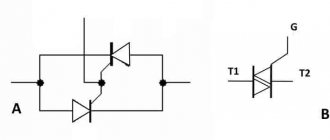
A two-color LED with two terminals consists of two back-to-back diodes connected in a common housing. Moreover, the body, or, more precisely, the lens, has standard dimensions and also only two terminals.
A special feature is that each LED terminal serves as the anode of one LED and the cathode of the second.
If you apply a plus to one pin and a minus to the second pin of the power supply, then one LED will be locked, and the second will light up, for example, green.
When the polarity of the power supply is changed, the green LED will be locked, and the red LED will light up.
Two-color LEDs are available in the following color combinations:
- Red Green;
- blue yellow;
- green - amber;
- Red Yellow.
How to connect a two-color LED with two terminals to a 220 V network
Such an LED is convenient to use on alternating current, since there is no need to use a reverse diode. Therefore, to connect a two-color LED to 220 V AC voltage, it is enough to add only a current-limiting resistor.
It is necessary to immediately make an amendment here that the nominal voltage in the network, which is also the same in the outlet, starting from October 2015, is no longer the usual 220 V, but 230 V. These and other data are reflected in GOST 29433-2014. The same standard provides permissible deviations from the rated voltage value of 230 V:
— nominal value 230 V;
— maximum 253 V (+10%);
— minimum 207 V (-10%);
— minimum under load 198 V (-14%).
Based on these assumptions, it is necessary to calculate the resistance of the current-limiting resistor so that it does not overheat and sufficient current flows through the LED for it to glow normally with the maximum permissible voltage fluctuations in the network.
Calculation of a current-limiting resistor
Therefore, although the nominal current value is 20 mA, we will take the calculated current value of a two-color LED as 7 mA = 0.007 A. At this value, it glows normally, since the brightness of the LED is not directly proportional to the current flowing through it.
Let's determine the resistance of the current-limiting resistor at a rated voltage in the socket of 230 V:
R = U/I = 230 V / 0.007 A = 32857 Ohm.
From the standard range of resistor values we select 33 kOhm.
Now let's calculate the power dissipation of the resistor:
P = I2R = 0.0072∙33000 = 1.62 W.
We accept a 2-watt resistor.
Let us recalculate for the case of the maximum permissible voltage at a given value of the resistor resistance:
I = U/R = 253 / 33000 = 0.0077 A = 7.7 mA.
P = I2R = 0.00772∙33000 = 1.96 W.
As you can see, when the voltage increases by an acceptable 10%, the current will also increase by 10%, however, the power dissipation of the resistor will not exceed 2 W, so it will not overheat.
When the voltage decreases by an acceptable amount, the current will also decrease. At the same time, the power dissipation of the resistor will also decrease.
Hence the conclusion: as an indicator of the presence of a mains voltage of 230 V, it is enough to just use a two-color LED with two terminals and a current-limiting resistor with a resistance of 33 kOhm with a dissipation power of 2 W.
If you look at such a semiconductor device when alternating current flows through it, you will see that both LEDs glow simultaneously.
In fact, they alternately flicker at a frequency of 50 Hz, but our eyes do not have time to track such fast flickers and give us a continuous image.
diodov.net
Connection
The easiest way to connect RGB LEDs to a power source is to connect to an Arduino microcontroller. The common lead (usually the longest one) is soldered to the "Gnd" pin, and the rest are connected to the corresponding points marked D12, D10 and D9. Contacts cannot be soldered directly; each of them (except the common one) must have a current-limiting resistor.
When connecting an LED with a common anode, the negative contact “Gnd” is used, located in the same row as the cathodes. If a common cathode connection is used, the positive “Gnd” contact from the opposite row is used.
Two-color LED with three terminals
This product is in great demand. Essentially, these are several LEDs in a single housing, thanks to which the colors are mixed and the product will shine in different shades, which can light up sequentially. A two-color LED also comes with three terminals. The color changes based on how the current flows and in what direction. In this case, the diodes are connected in parallel. If the current flows in a straight direction, then one diode does not light up. The opposite happens if the current flows in the opposite direction.
The colors of the products can be: green, red, blue, etc., tones and shades are obtained by combining colors. The purpose of devices with LEDs is different. They are most often used in decoration, advertising lighting structures, and alarm systems. Also, products with multi-color LEDs are widely in demand in everyday life and electronic devices. They are found in phones, modern gadgets, cameras and other products. It's easy to see how the LED works. For example, when the battery is charged, the light glows green, and when the battery is discharged, it glows red.
It is important to know that an LED, which has three outputs, has more capabilities. This number of pins gives the right to autonomously control the operation of the crystals and obtain a more complete palette of shades when mixing colors
You can also adjust the brightness of the light using special devices (switches, PWM modulators)
Application
All RGB LEDs are used for decoration and design of objects. They perform different tasks:
- create advertising backlight;
- lighting effects at concert venues;
- design of entertainment events;
- decoration and ceremonial lighting of buildings;
- decoration of fountains, monuments, bridges, etc.
Interesting! In addition, lighting design of interiors is becoming fashionable, in which designer multi-color solutions are actively used. When you change the shade of the glow, the color of the furniture visually changes, and the room gets a new, unusual look.