Light-emitting diodes (also known as led) have been actively used for many years both in the production of televisions and as the main lighting of a house or apartment, but the question of how to properly connect LEDs is still relevant today.
Today there are a huge number of them, of varying power (super-bright Piranha), operating on constant voltage, which can be connected in three ways:
- Parallel.
- Consistently.
- Combined.
There are also specially designed circuits that allow you to connect the LED to a stationary 220V household network. Let's take a closer look at all the LED connection options, their advantages and disadvantages, as well as how to do it yourself.
Basic principles of connection
As mentioned earlier, the design of a light-emitting diode involves connecting them exclusively to a direct current source. However, since the working part of the LED is a semiconductor silicon crystal, it is very important to maintain polarity, otherwise the LED will not emit a luminous flux.
Each LED has technical documentation, which contains instructions and directions for correct connection. If there is no documentation, you can look at the LED markings. The marking will help you identify the manufacturer, and knowing the manufacturer, you can find the required datasheet, which contains information on the connection. Here, this is not a tricky piece of advice.
How to determine polarity?
There are only 3 ways to resolve the issue:
- Constructively . According to standards accepted throughout the world, on a regular LED (not SMD type), the long leg is always the “+” or the anode. For an LED to work, a positive half-wave must be supplied to it. And the short one is the cathode.
- Using a multimeter. To check, you need to set the device switch to the “Test” mode and install the red multimeter probe on the anode, and the black probe on the cathode. As a result, the LED should light up. If this does not happen, you need to change the polarity (black to the anode, and red to the cathode). If the result does not change, then the LED has failed (to establish a more accurate diagnosis, read how to check the LED).
- Visually . If you look closely at the LED, you can see 2 tips near the crystal. The larger one is the cathode, the smaller one is the anode.
We've sorted out the polarity, now we need to decide how to connect the LED to the network. For those who do not understand, read a detailed and interesting article on determining the polarity of an LED. In it we have collected all possible methods of checking, and even using a battery.
LED pinout
By pinout we usually understand the appearance (body design) of the LED. Each manufacturer produces LEDs in its own housing, depending on the structure and purpose. There is no single standard, as in LED lamps; let me remind you that the most common lamp bases are: e27, e14.
There is no single standard for LED pinout. Each manufacturer does as they see fit. As a result, on store shelves we get a lot of LEDs that differ in shape, appearance, and design.
From the whole set, it is still possible to single out a couple of small groups. For example, the most common simple LEDs are made in a transparent or colored housing made of durable plastic or glass, and have the shape of a cylinder, the edge of which is most often rounded.
More expensive LEDs consist of several parts: a base and a lens. There are conductive tracks on the base, and the lens is made of high-quality material, which serves as a light diffuser.
The base is made in the form of a circle or square. Polarity on a square is indicated by a beveled corner. For example, CREE LEDs look like this:
A non-standard pinout may occur when repairing electronic units and cause certain difficulties in determining polarity. The pinout of the LED determines its polarity, knowledge of which is required for repair or correct installation of the LED in the circuit.
It is not always possible to determine the polarity in the usual ways, due to the non-standard pinout of the LED: the special structure of the housing, the thickening of one of the LEDs and other reasons. Therefore, in such cases, whatever one may say, you will have to resort to electrical measurement.
Designation of LEDs on the diagram
The LED in the diagram is indicated as a regular diode with two arrows pointing to the side, indicating the emission of light. The diode itself can be depicted either in a circle or without it.
On the side of the nose of the triangle there is a cathode, and on the side of the back of the triangle there is an anode. Sometimes on the diagram you can see the designations of the anode and cathode in the form of the letters A and K or + and -, which respectively mean anode and cathode or plus and minus.
The semiconductor element is signed on domestic circuits with the letters HL (HL1, HL2, etc.) - this is according to GOST. In foreign standards, the LED designation on the diagram is similar to the Russian one. It is signed with a different word - LED (LED1, LED2, LED3, etc.), which translated from English stands for light - emitting diode - light-emitting diode.
Do not confuse the designation of an LED on the diagram with a photodiode. At first glance it may seem that they are the same, however, upon closer examination, a significant difference is visible: the arrows of the photoresistor are directed towards the diode (a triangle with a stick at the sharp end).
The second difference is the letter designation of the photoresistor - VD or VB, which means photocell.
In conclusion, I would like to say that labeling is very important. Knowing its decoding allows you to determine the main parameters of the LED without opening the datasheet. It is unrealistic to remember the markings of all manufacturers, and there is no need; it is enough to know the decoding of the main brands.
Connecting LEDs to 220V voltage
The first thing you need to know when connecting to a 220V network is that for a nominal glow, a current of 20 mA must pass through the LED, and the voltage drop across it should not exceed 2.2-3V. Based on this, it is necessary to calculate the value of the current-limiting resistor using the following formula:
in which 0.75 is the reliability coefficient of the led, U pit is the voltage of the power source, U pad is the voltage that drops across the light-emitting diode and creates the luminous flux, I is the rated current passing through it, and R is the nominal resistance for regulating the passing current After appropriate calculations, the resistance value should correspond to 30 kOhm.
However, do not forget that a large amount of heat will be generated at the resistance due to the voltage drop. For this reason, it is additionally necessary to calculate the power of this resistor using the formula:
For our case, U will be the difference between the supply voltage and the drop voltage across the LED. After appropriate calculations, to connect one LED, the resistance power should be 2W.
After determining the rating and power of the resistance, you can assemble a circuit to connect one LED to 220V. For its reliable operation, it is necessary to install an additional diode that will protect the light-emitting diode from breakdown when an amplitude voltage of 315V (220*√2) occurs at the LED terminals.
The circuit is practically not used, since very large losses occur in it due to heat generation in the resistance. Let's consider a more efficient connection diagram to 220 V:
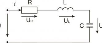
In the diagram, as we can see, a reverse diode VD1 is installed, which passes both half-waves to the capacitor C1 with a capacity of 220 nF, on which the voltage drops to the required nominal value.
Resistance R1 with a nominal value of 240 kOhm discharges the capacitor when the network is turned off, and does not play any role during operation of the circuit.
But this is a simplified model for connecting LEDs; most LED lamps already have a built-in driver (circuit) that converts 220V AC voltage into 5-24V DC voltage for their reliable operation. You can see the driver circuit in the following photo:
Some tips for creating a garland
When choosing the color of your future Christmas tree decoration, you should not pay attention to the RGB elements.
Assembly for a novice craftsman can become too complicated, and spending extra money to later connect them like ordinary components will be an unaffordable luxury. It is best to connect LEDs of different colors in parallel. Of course, you will have to make additional calculations of the resistor parameters, but the result will be much more interesting than when using single-color emitters. It is clear that a ready-made LED garland in a store is quite cheap. But you should understand that a product made by yourself will seem many times more beautiful. And the satisfaction that everything turned out as planned cannot be measured by any money.
When making such decorations, you should be extremely careful to ensure that there are no bare areas left and that the wires inside the controller do not overlap. The contacts must be properly soldered to avoid heating. It is necessary to understand that it will be located on the tree, and the needles flare up very quickly due to the resin it contains.
It makes sense to replace the power cable running from the controller to the socket - Chinese manufacturers are trying to save on everything. It is for this reason that the strands of this wire are slightly thicker than a hair. After opening the controller case, it makes sense to check the quality of soldering connections and contacts - in cheap models this is a sore spot.
Connecting LEDs to a 12V network
12 volts is a safe voltage that is used in particularly hazardous areas. These include bathrooms, baths, inspection pits, underground structures and other premises.
To connect to a DC voltage source rated 12V, similarly, to connect to 220V networks, a damping resistance is required. Otherwise, if you connect it directly to the source, the LED will instantly burn out due to the larger current flowing through.
The nominal value of this resistance and its power are calculated using the same formulas:
Unlike 220V circuits, to connect one LED to a 12V network we need a resistance with the following characteristics:
- R = 1.3 kOhm;
- P = 0.125W.
Another advantage of the 12V voltage is that in most cases it is already rectified (constant), which greatly simplifies the connection diagram. It is recommended to additionally install a voltage stabilizer such as KREN or an equivalent.
As we already know, a light-emitting diode can be connected to both 12V and 220V circuits, however, there are several variations of their connection to each other:
- Consistent.
- Parallel.
Types and main parameters of LEDs
In the diagram, the LED is indicated as a regular diode with two parallel arrows pointing outward, indicating its emitting nature. There are a large number of types of LEDs on sale, which differ in functionality, design, power, glow color and other properties.
Based on their purpose, LEDs are divided into two types - indicator and lighting.
Indicative:
- SMD LEDs;
- super bright Super Flux “Piranha”;
- DIP LEDs (Direct In-line Package);
- Straw Hat (“straw hat”).
Lighting:
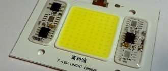
- COB (Chip On Board) LEDs;
- SMD LED;
- filament (Filament LED).
Indicative
Indicator LEDs are characterized by low power and moderate brightness. They are used for color indication of operating modes of various devices and equipment, as well as for illumination of displays and instrument panels. Types of indicator LEDs:
- DIP LEDs. The emitter crystal is located in an output housing, which most often is a convex lens. The downside is the small radiation scattering angle.
- “Piranha” is an ultra-high brightness emitter with four pins, ensuring its convenient mounting on the board. Demanded for illuminating devices in cars and advertising signs.
- "Straw Hat" A cylindrical two-terminal device with a significant radiation scattering angle and an increased lens diameter. Used in decorative structures and alarm lights.
- SMD LEDs. Ultra-high brightness devices are housed in housings designed for SMT mounting. Their markings indicate dimensions in inches (hundredths thereof) or in mm. LED strips are manufactured based on SMD LEDs.
Lighting
Lighting LEDs are found in the design of lanterns, headlights, and strips. They differ in the power and brightness of the glow. Most lighting fixtures are housed in SMT mounting housings. Available in two varieties of white:
- cool white – cold;
- warm white – warm.
An SMD lighting LED is a heat-sinking substrate on which a emitting crystal treated with a phosphor composition is mounted.
Serial connection
When connected in series through a current-limiting resistor, several LEDs are assembled into one chain, and the cathode of the previous one is soldered to the anode of the next one:
In the circuit, one current (20mA) will flow through all LEDs, and the voltage level will consist of the sum of the voltage drop across each. This means that using this connection diagram, you cannot include any number of LEDs in the circuit, because it is limited by voltage drop.
Voltage drop is the level of voltage that a light-emitting diode converts into light energy (glow).
For example, in the circuit the voltage drop across one LED will be 3 Volts. There are a total of 3 LEDs in the circuit. Power supply 12V. We consider 3 Volts * 3 led = 9 V - voltage drop.
After simple calculations, we see that we cannot include more than 4 LEDs (3 * 4 = 12V) in a parallel connection circuit, powering them from a regular car battery (or other source with a voltage of 12V).
If we want to connect more LEd in series, we will need a power supply with a higher rating.
This scheme was quite often found in Christmas tree garlands, however, due to one significant drawback, modern LED garlands use a mixed connection. We'll look at what the drawback is below.
Disadvantages of daisy chaining
- If at least one element fails, the entire circuit becomes inoperative;
- To power a large number of LEDs you need a high voltage source.
Installation features
To correctly connect spotlights, you need not only to choose the right circuit. It is necessary to follow a certain sequence of actions, which depends on the type of ceiling.
You just need to connect a few spotlights - and you have a beautiful interior
In suspended ceilings
Spotlights are usually installed with suspended or suspended ceilings. If the ceilings are suspended, all wires are laid in advance. They are attached to the ceiling without connecting to power, the lamps are placed and secured on pendants, then the wires are connected to them and the operation is checked.
Prepared for installation of suspended ceilings
Before installing suspended ceilings, turn off the power, remove the lamps and remove parts that may be damaged by temperature. After installing suspended ceilings, holes are cut in the material (the lamps are visible or can be felt), sealing rings are installed, and then the lamps are assembled.
In plasterboard ceilings
If the ceiling is made of plasterboard, you can proceed according to the same scheme, but the lamps must be installed after the ceiling has been plastered. That is, separate the wiring and leave the ends of the wiring hanging freely. To avoid problems with determining the location of lighting fixtures, it is necessary to draw a detailed plan indicating the exact distances from the walls and from each other. According to this plan, markings are made and holes are cut out using a drill with a crown of the appropriate size. Since there may be small movements - a few centimeters - when cutting the cable, leave a margin of 15-20 cm. This will be quite enough (but do not forget that the wires are attached to the main ceiling and they should extend 7-10 cm beyond the level of the drywall. If the ends turn out to be too long, you can always shorten them, but extending them is a big problem.
If you need to install a converter
There is a second way to connect spotlights to a plasterboard ceiling. It is used if there are few light sources - four to six pieces. The entire installation of spotlights along with wiring is done after the work on the ceiling has been completed. Before installation begins, the cable/cables from the junction box are led beyond the ceiling level. After finishing the puttying and sanding work, markings are made and holes are drilled. The cable is passed through them, bringing the ends out. Then the lamps themselves are installed.
Everything is simple, but this method cannot be called correct: the cables simply lie on the drywall, which definitely does not comply with fire safety standards. You can still turn a blind eye to this if the ceiling is concrete, the cable is non-flammable, the cross-section of the wire is not small, and the connection of the wires is done correctly.
Sequence of work in photo format
If the floors are wooden, the PUE requires installation in non-flammable all-metal trays (cable ducts) or metal pipes. You can install such wiring only before starting work on the ceiling. It is very undesirable to violate installation rules - wood, electricity, heat generation during operation... not the safest combination.
Parallel connection
In this situation, everything happens the other way around. Each LED has the same voltage level, and the current is the sum of the currents passing through them.
Following from the above, we conclude that if we have a 12V source and 10 LEDs, the power supply must withstand a load of 0.2A (10 * 0.002).
Based on the above calculations, for a parallel connection you will need a current-limiting resistor with a nominal value of 2.4 Ohms (12 * 0.2).
This is a deep misconception!!! Why? You will find the answer below
The characteristics of each LED, even of the same series and batch, are always different. In other words: in order for one to light up, it is necessary to pass through it a current with a nominal value of 20 mA, and for the other this nominal value may already be 25 mA.
Thus, if only one resistance is installed in the circuit, the nominal value of which was calculated earlier, different currents will flow through the LEDs, which will cause overheating and failure of LEDs designed for a nominal value of 18 mA, and more powerful ones will shine at only 70% of the nominal value .
Based on the above, it is worth understanding that when connecting in parallel, it is necessary to install a separate resistance for each.
Disadvantages of parallel connection:
- A large number of elements;
- When one diode fails, the load on the others increases.
Learn more about how diodes work
Which LED connection should I choose: series or parallel? This greatly depends on the operating conditions and the power source, as well as the voltage and current stabilization system. To make the right choice, you need to consider both options.
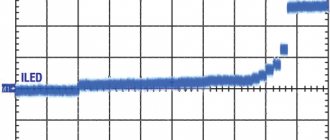
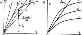
Initially, we were talking about the current-voltage characteristic for a reason; let’s consider in detail its form for LED devices.
Please note that in the voltage range lower than 2.5V, very little or no current flows through the LED. Having overcome the level of 2.5 volts, current begins to flow through the diode and it lights up in the area from 2.5 to 3 volts. After this level, the current begins to increase rapidly.
For 5 mm white light diodes, the operating current is 20 mA at 3V, and at 3.5 volts the current will be 80 mA, which is four times higher than the nominal value.
Although the brightness of the diode depends on the current flowing through it, at excessively high values the LED does not glow much brighter than at nominal value. Therefore, you should not experiment with high indicators - your diodes will simply burn out.
Voltage values may vary depending on the types and design of LEDs, this is influenced by their number in one package, color, and even the material that was chosen as the basis of the chip.
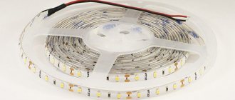
Mixed connection
This connection method is the most optimal. All LED strips are assembled using this principle. It involves a combination of parallel and serial connections. You can see how it is done in the photo:
The circuit involves connecting in parallel not individual LEDs, but serial chains of them. As a result of this, even if one or more chains fail, the LED garland or strip will still shine equally.
We looked at the main ways to connect simple LEDs. Now let's look at the methods for connecting high-power LEDs, and what problems you may encounter if connected incorrectly.
You need to know this
The main thing is to remember safety precautions. The presented circuits are powered by 220 V AC, and therefore require special attention during assembly. Connecting the LED to the network must be carried out in strict accordance with the circuit diagram.
Deviation from the diagram or negligence can lead to a short circuit or failure of individual parts. When you turn it on for the first time, it is recommended to let the assembly work for a while to make sure it is stable and does not overheat the elements.
To increase the reliability of the device, it is recommended to use previously tested parts with a margin of maximum permissible voltage and power values. You should carefully assemble transformerless power supplies and remember that they do not have galvanic isolation from the network.
The finished circuit must be reliably isolated from adjacent metal parts and protected from accidental contact. It can only be dismantled with the power supply switched off.
How to connect a powerful LED?
For powerful light-emitting diodes to work, just like simple ones, we need a power source. However, unlike the previous version, it should be an order of magnitude more powerful.
To illuminate a powerful 1W LED, the power source must withstand at least 350 mA of load. If the rating is 5W, then the DC power source must withstand a current load of at least 1.4A.
For the correct operation of a high-power LED, it is necessary to use an integrated voltage stabilizer of the LM type, which protects it from voltage surges.
If you need to connect not one, but several powerful LEDs, we recommend that you familiarize yourself with the rules for serial and parallel connection, which were described above.
Parallel connection of LEDs is not correct
I repeat once again - parallel connection of LEDs is used only when the power source is low voltage.
Despite the fact that this type of connection is not very welcome, it is often used. There is one rule in these types of connections - parallel connection of LEDs is never done using ONLY ONE resistor!!!
Well, or for those who only understand visual pictures, an incorrect parallel connection will look like this:
Naturally, the question arises - WHY can’t it be connected like this? And the point here is simple...
Connection errors
- Direct connection to power source. In this case, the LED will burn out instantly, since there is no current limiting resistor.
- Parallel connection via one resistor.
LEDs will gradually fail because the operating current is different for each one. - Serial connection with different current consumption.
With this connection scheme, there are 2 options: either some will simply shine dimmer than others, or those designed for less current will burn out. - Incorrectly selected limiting resistor.
If the resistance is incorrectly selected, a large current will flow through the LEDs, as a result of which they will overheat and eventually burn out. With high resistance, they will not shine at full strength. - Connection to an alternating voltage network rated 220V without a diode or other protection components. If when connecting from a 220V network, e
If you do not install an additional diode, an amplitude voltage value of 315V will appear on the LED, which will instantly disable it.
Calculation of resistance when connecting LEDs in parallel
Let's consider parallel connection of LEDs using the example of two power supplies. The data will be obtained based on twice the current consumption. Those. the limiting resistor has half the resistance than. if we powered one LED. In any case, it is worth remembering that no two LEDs are identical, even if they were produced by the same factory and from the same batch. All diodes have a variation in current consumption and internal resistance. A crystal with less resistance will draw more current. Thus, some distortion will arise. This can be determined visually. With higher consumption, the diode will glow stronger, with lower consumption, weaker. If the diodes are from the same batch, then the distortion will not be very noticeable, but if the LEDs are also from different manufacturers, then it is quite possible that the diode will burn out.
Let's go back to our sheep... The resistor is designed for double current consumption, and therefore if one burns out, the second one receives double the voltage and double the current. This is also critical. This rule is true not only for connecting two LEDs in parallel, but also for larger numbers with one resistor. If one burns out, the rest will fail in the shortest possible time, due to proportionally increasing voltage and current.
Video
Connection errors can lead to unpleasant consequences, from simple breakdown of LEDs to self-harm. Therefore, we strongly recommend watching a video where common errors are discussed.
Conclusion
After reading the article, we can conclude that all LEDs, regardless of the operating voltage, are always connected in parallel or in series - a school physics course. It is also worth remembering that no LED is connected directly to a 220V network; you should always use protective elements in the connection diagram. The type of protective elements used depends on the type of light-emitting diode being connected.
How to connect correctly?
When connecting LEDs in parallel, you need to use a limiting resistor for each diode, as shown in the figure below. This makes it possible to set the current for each of the elements of the electrical circuit.
LED Parallel Connection Diagram
Below is a diagram of NOT correctly connecting a resistor to a circuit.
This is not the right way to connect
When connecting LEDs and any other consumers in parallel, the voltage at their terminals will be equal. On the one hand, this is good, but not for diodes. Each LED, even a set taken from the same batch, has a small technological variation in parameters. The voltage required to achieve the rated current may vary slightly within tenths of a volt.
Above you saw the current-voltage characteristic of the device and you can easily conclude that a slight excess of the rated voltage leads to an avalanche-like increase in current and overheating. Some suggest excluding the resistor from this circuit; this connection of LEDs is the worst!
The total current in the circuit is equal to the sum of the currents in each of the branches of the parallel circuit. If you choose how to connect LEDs to operate in a circuit with high voltage (6 volts or more), it is better to use a series connection.