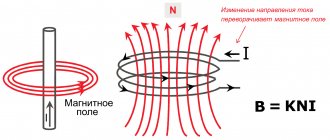
Today, probably, not a single apartment or private house can do without LED lighting. And street lighting is gradually changing to economical and durable LED elements. But looking at today’s topic of conversation, the question arises – what does the driver have to do with it (that’s how “driver” is translated from English)? This is the first question that comes to the mind of a person ignorant of LED lighting. In fact, without such a device, light diodes do not work with a voltage of 220 V. Today we will figure out what function the driver for LEDs performs, how to connect this device and whether it is possible to make it yourself.
Without such a device, the LEDs will not work
Why do we need drivers for LEDs and what are they?
The answer to the question of what is an LED driver is quite simple. This is a device that stabilizes the voltage and gives it the characteristics necessary for the operation of LED elements. To make it clearer, let's draw an analogy with the ballast of a fluorescent lamp, which also cannot work without additional equipment. The only difference is that the driver is compact in size and fits into the body of the light device. In essence, it can be called a stabilizing starting device or frequency converter.
Even inside the LED light bulb there is a miniature low power converter
Types of drivers.
By type they can be divided into:
Linear. They are most suitable if the input voltage is not stable. Features improved stabilization. Rarely distributed due to low efficiency. Generates more heat, suitable for low-power loads.
Driver internals
Appearance and circuit diagram of the LED 1338G7 driver.
Pulse. Based on PWM chips. They have high efficiency. They are characterized by low heating and long service life.
Recom PWM driver.
PWM chips create significant levels of electromagnetic interference. People with pacemakers are not recommended to stay in rooms where such drivers are used to power LEDs.
Driver working with dimmer. The principle is based on the use of a PWM controller. The principle is that the current on the LEDs is regulated. Low quality products give a shimmering effect.
Driver with dimmer.
Electronic view of the device.
Ideally, the electronic converter should be equipped with a transistor. Its role is to unload the control microcircuit. To eliminate or smooth out ripple as much as possible, a capacitor is mounted at the output.
This type of device belongs to the expensive category, but it is capable of stabilizing current up to 750 mA, which ballast mechanisms are not capable of.
The newest drivers are mainly installed on light bulbs with an E27 socket. An exception to the rule is Gauss GU5.3 products. They are equipped with a transformerless converter. However, the degree of pulsation in them reaches several hundred Hz
Pulsation is not the only drawback of converters. The second can be called electromagnetic interference in the high frequency (HF) range. So, if other electrical appliances are connected to the socket connected to the lamp, for example, a radio, you can expect interference when receiving digital FM frequencies, television, router, etc.
The optional device of a quality device must have two capacitors: one is electrolytic to smooth out ripples, the other is ceramic to reduce RF. However, such a combination can be found rarely, especially when talking about Chinese products.
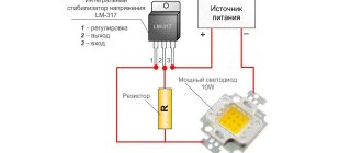
Those who have general concepts in such electrical circuits can independently select the output parameters of the electronic converter by changing the value of the resistors
Due to their high efficiency (up to 95%), such mechanisms are suitable for powerful devices used in various fields, for example, for car tuning, street lighting, and household LED sources.
Power supply based on capacitors.
Now let's move on to less popular devices - those based on capacitors. Almost all low-cost LED lamp circuits that use this type of driver have similar characteristics.
However, due to modifications by the manufacturer, they undergo changes, for example, the removal of some circuit element. Especially often this part is one of the capacitors - a smoothing one.
Due to the uncontrolled filling of the market with cheap and low-quality goods, users can “feel” one hundred percent pulsation in the lamps. Even without delving into their design, we can say that the smoothing element has been removed from the circuit
Such mechanisms have only two advantages: they are available for self-assembly, and their efficiency is equal to one hundred percent, since losses will only occur at pn junctions and resistances.
There are the same number of negative aspects: low electrical safety and high degree of pulsation. The second disadvantage is around 100 Hz and is formed as a result of rectification of the alternating voltage. GOST specifies a norm of permissible pulsation of 10-20%, depending on the purpose of the room where the lighting device is installed.
The only way to mitigate this drawback is to select a capacitor with the correct rating. However, you should not count on completely eliminating the problem - such a solution can only smooth out the intensity of the bursts.
Dimmable current converters.
Drivers-dimmers for dimmable LED bulbs allow you to change the incoming and outgoing current indicators, while reducing or increasing the brightness of the light emitted by the diodes.
There are two connection methods:
- the first involves a soft start;
- the second is impulse.
Consider the operating principle of dimmable drivers based on the CPC9909 chip, used as a regulating device for LED circuits, including those with high brightness.
Diagram of standard connection of CPC9909 with 220 V power supply. According to the schematic instructions, it is possible to control one or more powerful consumers
During a soft start, the microcircuit with the driver ensures gradual switching on of the diodes with increasing brightness. This process involves two resistors connected to the LD pin, designed to perform the task of smooth dimming. This is how an important task is achieved – extending the service life of LED elements.
The same output also provides analog regulation - the 2.2 kOhm resistor is replaced with a more powerful variable analogue - 5.1 kOhm. In this way, a smooth change in output potential is achieved.
The second method involves supplying rectangular pulses to the low-frequency output of the PWMD. In this case, either a microcontroller or a pulse generator is used, which are necessarily separated by an optocoupler.
With or without housing?
Drivers are available with or without a housing. The first option is the most common and more expensive. Such devices are protected from moisture and dust particles.
Devices of the second type are used for hidden installation and, accordingly, are inexpensive.
All presented devices can be powered from a 12 V or 220 V network. Despite the fact that open-frame models benefit in price, they lag significantly behind in terms of safety and reliability of the mechanism
Each of them differs in the permissible temperature during operation - this must also be taken into account when selecting.
Where are stabilizing devices used for LED elements?
LED drivers for LEDs are used in various fields:
- street lighting lamps;
- household lighting lamps;
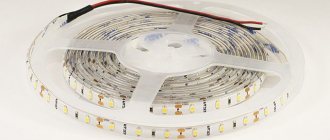
- LED strips and various lighting;
- office lamps with the form of fluorescent lamps.
Even daytime running lights of cars require the installation of such a device, but here everything is much simpler; you can get by with one resistor. And although the driver for an LED strip (for example) differs in characteristics from the voltage stabilizer of a light bulb, they perform the same function.
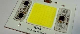
The difference in size is large, but the characteristics are the same
sxemy-podnial.net
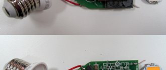
I present to your attention the driver circuits for LED lamps that I recently had to repair. I'll start with a simple one (photo 1, right) and the diagram in Figure 1.
LED lights. Photo 1.
LED lamp driver for CL1502. Rice. 1.
The CL1502 chip is installed in the circuit of this driver. Many microcircuits with similar functions have already been released, and not only in a package with 8 legs. There is a lot of technical data on this chip on the Internet, for example in [1]. The driver is assembled according to the “classical” scheme. The problem was that a couple of LEDs burned out. The first time I simply shorted them out, since I was far from “civilization.” He did the same the second time. And when the third pair burned out, I realized that this lamp had little time left to live. Simply short-circuiting pairs of LEDs will not do so easily. Something drastic was required. Previously, I studied the circuit design and operation of similar microcircuits in order to shorten an LED lamp in a 36-watt tubular glass fluorescent housing from a length of 120 centimeters to 90, since there was such a lamp installed above the desktop. And everything was successful and works. And here. As far as I understand the operation of such lamps, using such drivers, nothing bad should happen after short-circuiting at least all the LEDs except the last pair. After all, everything in them is decided by the current sensor, in this circuit these are resistors R3 and R4. The voltage generated by these resistors, passing through pins 7 and 8 of the CL1502 microcircuit to the comparator for turning off the power switch, works perfectly. But something still burns the LEDs. But what? My guess is that the driver itself is burning them! The LEDs used in this lamp are similar to 2835SMDLED (0.5 W per LED). And if this is really them, then the declared power of the lamp is completely justified. But I have strong suspicions that the lamp contains 3528SMDLEDs, which have parameters almost an order of magnitude lower. But this is very difficult for me to understand, since there are no symbols on SMD LEDs. What did I do? I removed resistor R4 from the board. At the same time, the current through the LEDs decreased and... the LEDs stopped burning. Interestingly, in a construction trailer that contained three lamps of the same type, all three had to be repaired sequentially. And everywhere I had to remove one resistor. And yes, the luminous flux has dropped everywhere, although it is difficult to determine with the eye, but if you compare it, it is noticeable.
In another trailer, there were two lamps with external dimensions of 595x595 mm... And they also “burned”. In these lamps, the cells consisted of four LEDs in parallel and there were 28 such cells. Since there was a similar circuit there (it was not possible to raise it), I simply removed one resistor at a time.
As a result, we can conclude that repairs can be carried out using a similar method, that is, reducing the current through the LEDs, since it is better to let them shine darker than to go out completely. Although, of course, it would be more correct to change all the LEDs to 2835SMDLED, but this is subject to their availability.
LED lamp driver for B77CI. Rice. 2.
I “picked up” the circuit of the second driver, shown in Figure 2, from a lamp that I found in scrap metal, with mechanical damage to the housing. Figure 3 shows a diagram of four LED boards of 9 W each. I wanted to remove the LEDs for spare parts. And I didn’t even immediately notice the nondescript box with the driver. The scheme turned out to be almost a “monster”.
LED lamp lantern. Rice. 3. Appearance of the driver board on the B77CI. Photo 2.
The presence of two microcircuits, two powerful field-effect transistors, two chokes and two electrolytic capacitors 220 microns x 100 V connected in parallel indicated that the developers did a great job. There is also a pretty good filter circuit (see photo 2). The DX3360T chip is apparently a voltage stabilizer, and possibly with a power corrector. I found only a nondescript picture on the Internet, without a description. But I didn’t find anything for the B77CI chip, and I put the names of the pins on the diagram according to intuition. I have not seen this driver in action. But I assume good work. But if you have to reduce the current through the LEDs, then you need to either remove one or two resistors Rs4..Rs6 from the board, or replace them with other calculated ones.
And further. It is not at all clear how heat removal from LEDs is organized in such lamps. After all, they are sealed onto scarves made of foil fiberglass, 5 mm wide. and about 1 mm thick.? I think almost nothing. Everything is consumer goods.
References: 1. https://www.dianyuan.com/upload/community/2014/04/10/1397117125-79110.pdf
Operating principle of a 220V LED lamp driver circuit
The operating principle of the device is to maintain a given current at the output voltage (regardless of its value). This is the difference from a stabilizing power supply, which is responsible for voltage.
The simplest converter circuit for light diode tape
Looking at the circuit, we see that the current, passing through the resistance, is stabilized, and the capacitor gives it the desired frequency. Then the rectifying diode bridge comes into play. We get a stabilized forward current on the LEDs, which is again limited by resistors.
To design LED lamps, power sources—drivers—are constantly required. With a large volume, it is quite possible to assemble the drivers yourself, but the cost of such drivers is not so low, and manufacturing and soldering double-sided printed circuit boards with SMD components is a rather labor-intensive process at home.
I decided to make do with a ready-made driver. What was needed was an inexpensive driver without a housing, preferably with the ability to adjust the current and dimming.
The choice fell on the Chinese manufacturer QIHANG, which produces a wide range of these products.
Where and how to buy can be read in my article on the profile blog mysku.ru. Let me just say that 20W drivers for 6-10 600mA LEDs cost me about $2.5
Driver Specifications
- Item No.: QH-20WLP6 ~ 10X3W
- Input voltage: AC 85~277V
- Output voltage: DC 18~35V
- Output current: 0.6A
- Output power: 20W
- Efficiency: ? 88%
- Output accuracy: ±3%
- Power factor (PF): ? 0.95
- Output ripple size: ? 50 mV (not true)
- Dimensions: length X width X height = 47 x 20 x 13mm
- Operating temperature: -40~+85°C
- Weight 20g
The photo shows the QH7938 driver chip. A search on the Internet leads to a datasheet for this microcircuit in Chinese. The datasheet is clearly not complete, the diagram does not have enough part values and there are clearly more elements on the driver. And what to do with the mysterious DIM and RTH legs?
Thanks to the user Muska Sarayan14 who has already tinkered with this driver and even drew a diagram.
I redrawn the diagram and modified it a little
I connect a chain of 9 three-watt LEDs. Everything works, the current is stable 598mA, but the device in AC voltage measurement mode shows output ripple of about 1V or more than 3%. Where is the 50mV stated in the specifications?
Improvement No. 1. Reducing output ripple.
How to reduce output voltage ripple? That's right, capacitors. Capacitors can be placed in two places - increase the output capacitance and add a capacitor at the input after the bridge in parallel with the 0.22 µF film capacitor.
For testing, I use a pointer device in AC voltage measurement mode and a homemade lux meter that measures pulsations of the light flux
Characteristics without capacitors ~0.9V and 8.7% (light flux ripple)
The output capacitor is expected to reduce ripple by half ~0.4V and 4%
But a 10uF capacitor at the input reduces ripple by 9 times ~0.1V and 1%, although adding this capacitor significantly reduces PF (power factor)
Both capacitors bring the output ripple characteristics closer to the specifications ~ 0.05V and 0.6%
So, ripple was defeated with the help of two capacitors from the old power supply.
Improvement No. 2. Setting the driver output current
The main purpose of the drivers is to maintain a stable current to the LEDs. This driver consistently produces 600mA.
Sometimes you want to change the driver current. This is usually done by selecting a resistor or capacitor in the feedback circuit. How are these drivers doing? And why are three parallel low-resistance resistors R4, R5, R6 installed here?
Everything is correct. They can set the output current. Apparently, all drivers are of the same power, but for different currents and differ precisely in these resistors and the output transformer, which gives different voltages.
If we carefully remove the 1.9 Ohm resistor, we get an output current of 430 mA, removing both 300 mA resistors.
You can go the opposite way by soldering another resistor in parallel, but this driver produces a voltage of up to 35V and with a higher current we will get excess power, which can lead to driver failure. But 700mA is quite possible to squeeze out.
So, by selecting resistors R4, R5 and R6, you can reduce the driver output current (or increase it very slightly) without changing the number of LEDs in the chain.
Revision 3. Dimming
There are three pins on the driver board labeled DIMM, which suggests that this driver can control the power of the LEDs. The datasheet for the microcircuit speaks about the same thing, although it does not contain typical dimming circuits. From the datasheet you can glean information that by applying a voltage of -0.3 - 6V to leg 7 of the microcircuit, you can obtain smooth power control.
Connecting a variable resistor to the DIMM pins does not lead to anything, in addition, leg 7 of the driver chip is not connected to anything at all. So again improvements.
Solder a 100K resistor to leg 7 of the microcircuit
Now by applying a voltage of 0-5V between ground and resistor we get a current of 60-600mA
To reduce the minimum dimming current, you must also reduce the resistor. Unfortunately, nothing is written about this in the datasheet, so you will have to select all the components experimentally. I was personally satisfied with dimming from 60 to 600mA.
If you need to organize dimming without external power, you can take the driver supply voltage ~15V (leg 2 of the microcircuit or resistor R7) and apply it according to the following circuit.
Well, finally, I feed PWM from D3 of the Arduino to the dimming input.
I’m writing a simple sketch that changes the PWM level from 0 to maximum and back:
#include
void setup() { pinMode(3, OUTPUT); Serial.begin(9600); analogWrite(3,0); }
void loop() { for( int i=0; i< 255; i+=10 ){ analogWrite(3,i); delay(500); } for( int i=255; i>=0; i-=10 ){ analogWrite(3,i); delay(500); } }
I get dimming using PWM.
PWM dimming increases output ripple by about 10-20% compared to DC control. The maximum ripple increases approximately twice when the driver current is set to half the maximum.
Checking the driver for short circuit
The current driver must respond correctly to a short circuit. But it’s better to check the Chinese. I don't like such things. Stick something under voltage. But art requires sacrifice. We short-circuit the driver output during operation:
The driver tolerates short circuits normally and restores its operation. There is short circuit protection.
Let's sum it up
Pros of the driver
- Small dimensions
- Low cost
- Possibility of current adjustment
- Dimmable
Minuses
- High output ripple (eliminates by adding capacitors)
- The dimming input needs to be soldered
- Little normal documentation. Incomplete datasheet
- During operation, another disadvantage was discovered - interference on the radio in the FM range. It can be treated by installing the driver in an aluminum case or a case covered with foil or aluminum tape.
The drivers are quite suitable for those who are comfortable with a soldering iron or for those who are not, but are willing to tolerate output ripples of 3-4%.
useful links
- Discussion on the ledway.ru forum
- Datasheet for QH7938
- Discussion on the import forum
- Product on TAOBAO
- Product on Aliexpress
- Manufacturer's website (Chinese)
From the series - cats are liquid. Timofey - 5-6 liters)))
Driver Features Worth Considering
The characteristics of the converters required in a particular case are determined based on the parameters of the LED consumers. The main ones can be called:
- Rated power of the driver - this parameter must exceed the total power consumed by the light diodes that will be in its circuit.
- Output voltage - depends on the magnitude of the voltage drop across each of the light diodes.
- Rated current , which depends on the brightness of the glow and the power consumption of the element.
Different colors of LED elements have different voltage drops.
Important to know! The voltage drop across an LED depends on its color. For example, if you can connect 16 red LEDs to a 12 V power supply, then the maximum number of green ones will be 9.
Main conclusions
Even the simplest LED, if it is powered by 220 V AC, requires a driver for stable operation. Its main meaning is stabilization, current rectification and voltage reduction. Whether it is made with your own hands or bought in a store, it is characterized by three main parameters:
- Rated current.
- Power.
- Output voltage.
The driver for powering LEDs from 220 V consists of three interacting stages - a capacitive voltage divider, a diode rectifying bridge and a stabilizer. To install such a device with your own hands, you will need to stock up on the necessary radio components and a set of tools, which can be purchased at any specialized store. When assembling the device, you must strictly adhere to the proposed diagram and instructions.
If you have experience creating a similar driver with your own hands or otherwise modifying it for an LED powered by a 220 V network, be sure to write about it in the comments.
Division of LED drivers by device type
Converters can be divided into two types - linear and pulse. Both types are applicable to light diodes, but the differences between them are noticeable in both cost and technical characteristics.
Linear current converter and its circuit
Linear converters are characterized by their simple design and low cost. But such drivers have a significant drawback - the ability to connect only low-power light elements. Part of the energy is spent on heat generation, which contributes to a decrease in efficiency.
Pulse converters are based on the principle of pulse width modulation (PWM) and during their operation, the values of output currents are determined by such a parameter as the duty cycle. This means that there is no change in the pulse frequency, but the duty cycle can vary by values from 10 to 80%. Such drivers allow you to extend the life of light diodes, but have one drawback. During their operation, it is possible to induce electromagnetic interference. Let's try to figure out what this threatens a person with a simple example.
Switching regulators are slightly larger
A person living in an apartment or house has a pacemaker. At the same time, in a small room there is a chandelier with many devices operating on pulsed ice drivers for LED lamps. The pacemaker may begin to malfunction. Of course, this is exaggerated and to create such strong interference you need a lot of lamps that are located at a distance of less than a meter from the pacemaker, but there is still a risk.
And this is a converter for a more powerful LED
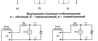
Key type voltage stabilizers
This kind of 12V switching voltage regulator has an efficiency of 60%. The main problem is that it is not able to cope with electromagnetic interference. In this case, devices with a power of more than 10 W are at risk. Modern models of these stabilizers can boast a maximum voltage of 12 V. The load on the resistors is significantly reduced. Thus, on the way to the capacitor, the voltage can be completely converted. The current frequency is directly generated at the output. The wear on the capacitor in this case is minimal.
Another problem is related to the use of simple capacitors. In fact, they performed quite poorly. The whole problem lies precisely in the high-frequency emissions that occur in the network. To solve this problem, manufacturers began to install electrolytic-type capacitors on the pulse voltage stabilizer (12 volts). As a result, the quality of work was improved by increasing the capacity of the device.
How to choose a driver for an LED: some nuances
Before purchasing a converter, calculate the power consumed by the LEDs. The rated power of the device must exceed this figure by 25÷30%. Also, the stabilizer must match the output voltage.
If you plan to place it hidden, it is better to choose a converter without a housing - the cost will be lower with the same technical characteristics.
The Chinese do everything quite simply and without unnecessary details.
Important! Drivers made in China usually do not meet the stated specifications. You shouldn’t skimp on purchasing a “made in” converter. It is better to give preference to a Russian manufacturer.
How to connect LED elements to the converter: methods and diagrams
LEDs are connected to the driver in two ways - in series or in parallel. For example, let's take 6 LED emitters with a voltage drop of 2 V. For a serial connection, you will need a 12 V and 300 mA driver. In this case, the glow will be even across all elements.
Connection diagram of the driver to the panel or light strip
By connecting the emitters in parallel in a group of 3, we will be able to use a 6 V converter, but at 600 mA. The problem is that due to the uneven voltage drop, one line will glow brighter than the other.
We calculate the characteristics of the converter for LEDs
For an accurate calculation, we first determine the power consumption of the LEDs. Afterwards, the issue with the connection diagram is decided - will it be parallel or serial. The output voltage and rated power of the required converter will depend on this. That's all the work that needs to be done. Now, in an electrical store or on an online resource, we select a driver according to the calculated indicators.
Before choosing a converter, you need to calculate the power consumed by the light diodes
Good to know! When purchasing a converter, ask the seller for a certificate of conformity for the product. If it is missing, it is better to refrain from purchasing.
What is a dimmable LED driver?
Dimmable is a driver for an LED lamp that supports changing input current parameters and is capable of changing output current parameters depending on this. This is achieved by changing the glow intensity of LED emitters. An example would be a controller for an LED strip with remote control. If desired, it becomes possible to “dim” the lighting in the room and give your eyes a rest. This is also appropriate if a child is sleeping in the room.
This device performs dimming
Dimming is performed from the remote control, or from a standard mechanical stepless switch.
Types of dimmable drivers
Types of dimmable drivers:
- Connect between the power supply and the light source. They allow you to control the energy that goes to the LED elements. The design is based on PWM modulators with microcontroller control. All energy goes to the LEDs in pulses. The energy that goes to the LEDs directly depends on the length of the pulses. Such driver designs are used mainly for operating modules with stabilized power supply. For example, for ribbons or tickers.
- The second type of device allows you to control the power supply. Control is carried out using a PWM modulator. The amount of current that flows through the LEDs also changes. As a rule, such designs are used to power those devices that require stabilized current.
It is necessary to take into account the fact that PWM regulation has a bad effect on vision. It is best to use driver circuits to power LEDs in which the current is regulated. But here’s one caveat: depending on the current value, the glow will be different. At a low value, the elements will emit light with a yellow tint; at a higher value, it will emit a bluish tint.
Chinese converters - what's special about them
Chinese friends are famous for their ability to counterfeit equipment so that it becomes impossible to use. The same can be said for drivers. When purchasing a Chinese device, be prepared for inflated declared characteristics, low quality and rapid failure of the converter. If you are going to build your first LED lamp, practice and gain skills in radio electronics, such products are indispensable due to their low cost and ease of execution.
If you add a capacitor to the Chinese converter circuit, the lamp life will increase
What affects the service life of converters
The causes of converter failure are:
- Sudden power surges in the network.
- Increased humidity if the device does not meet the degree of protection.
- Temperature changes.
- Insufficient ventilation.
- Increased dustiness.
- Incorrect calculation of consumer power.
This is what happens when the current stabilization device overheats.
Any of these reasons can be prevented or corrected. This means that it is within the power of a home craftsman to extend the service life of the stabilizing device.
PT4115 LED driver circuit with dimmer
We will talk about a Chinese manufacturer, which is an exception to the rule. A microcircuit on the basis of which you can assemble a simple converter made by him. The PT4115 microprocessor has good characteristics and is gaining popularity in Russia.
Stabilizer circuit based on PT4115 microprocessor
Article on the topic: If LED lighting and conventional regulators are not suitable, then dimmers are installed for 220 V LED lamps , which are slightly different in design and technically. Today we’ll figure out what they are, how to choose and even make such a device yourself.
The figure shows the simplest PT4115 driver circuit for LEDs, which can be assembled by a novice home craftsman without experience in working with radio electronics. An interesting feature of the microcircuit is an additional output (DIM) that allows the connection of a dimmer.
Lamp driver (LED) repair
Sometimes the light source refuses to work at the most inopportune moment. This can happen due to improper use or the fault of the manufacturer (this often happens with Chinese low-quality products).
The simplest driver for a 220 V LED lamp is often made using ordinary elements (diodes, resistors, etc.). In this circuit, one or more LEDs immediately fail when a capacitor or one of the bridge diodes breaks down. Therefore, these radio components are checked first.
Instead of LEDs, temporarily connect an ordinary 15-20 watt light bulb (for example, from a refrigerator). If all parts except the LED are intact, it lights up dimly.
The second option is a rectifier with a voltage divider, a pulse stabilizer on a microcircuit and an isolation transformer. If the chandelier malfunctions, all elements are checked sequentially. The scheme may differ from the one shown, but the search algorithm is the same.
LED lamp driver circuit
We recommend reading: DIY LED lamp repair
How to repair:
- First, check whether the LED matrices are receiving voltage. If there is one, look for faulty LED parts and replace them. If the voltage is OK, check the bridge diodes and input capacitors.
- If they are also intact, measure the supply voltage of the microcircuit (4th leg). If it differs from 15-17 V, this element is most likely faulty and should be replaced.
- If the microcircuit is intact and there are pulses on its 5th and 6th legs (checked with an oscilloscope), then the transformer and its circuits are “to blame” - the capacitor or diodes connected to it.
Replacing electrolytic capacitors in the driver for LED lamps.
Many people purchase long strings of LEDs mounted on flexible substrates. These are LED strips.
There are two options for such sources:
- only LED devices without additional parts;
- products with resistors soldered to each element or chain of 4-6 LEDs, which are designed so that at a voltage of 12-36 V and rated current the lighting elements do not burn out.
In both cases, drivers that have already been discussed above are often used. But sometimes the second version of LED strips is powered using a module, which is a transformer power supply.
Circuit diagram of a simple power supply.
When repairing a 36-watt LED lamp driver, if not a single LED or chain lights up, first check the transformer for an open circuit. Then diodes and rectifier capacitor. Parts R1 and C1 in such a scheme very rarely deteriorate.
If at least one or more elements are lit, the supply voltage is supplied. In this case, check the LEDs and change them.
It will be useful to read: Driver repair for LED strip 12 V 100 W.
How to make a driver for LEDs with your own hands
Any novice craftsman can assemble an LED lamp driver circuit. But this will require accuracy and patience. The stabilizing device may not work the first time. To make it clearer to the reader how the work is done, we offer several simple diagrams.
As you can see, there is nothing complicated in the driver circuits for LEDs from a 220 V network. Let's try to look at all stages of work step by step.
Step-by-step instructions for making a DIY LED driver
| Photo example | Action to be performed |
| To work, we need a regular power supply for the phone. With its help, everything is done quickly and easily. | |
| After disassembling the charger in our hands, we already have an almost complete driver for three one-watt LEDs, but it needs a little modification. | |
| We solder a 5 kOhm limiting resistor, which is located near the output channel. It is this that prevents the charger from supplying too much voltage to the cell phone. | |
| Instead of a limiting resistor, we solder in a tuning resistor, setting it to the same 5 kOhm. Subsequently, we will add voltage to the required level. | |
| 3 LEDs of 1 W each are soldered onto the output channel, connected in series, which gives us a total of 3 W. | |
| We find the input contacts and unsolder them from the printed circuit board. We don't need them anymore... | |
| ...and in their place we solder a power cord through which 220 V power will be supplied. | |
| If desired, you can put a 1 Ohm resistor in the gap and set all the indicators with an ammeter. In this case, the attenuation range of the LEDs will be wider. | |
| After complete assembly, we check the functionality. The output voltage is 5 V, the LEDs are not lit yet. | |
| By turning the knob on the resistor, we see how the LED elements begin to “flare up”. |
Be careful. From such a converter you can get a shock not only of 220 V (from the power cord), but also a shock of about 450 V, which is quite unpleasant (tested on myself).
Very important! Before you check the LED driver for functionality and connect it to a power source, you should once again visually check the correctness of the assembled circuit. Electric shock is life-threatening, and flash from a short circuit can cause damage to the eyes.
220 volt LED driver circuit
The 220 volt LED driver circuit is nothing more than a switching power supply.
As a homemade LED driver from a 220V network, we will consider the simplest switching power supply without galvanic isolation. The main advantage of such schemes is simplicity and reliability.
But be careful when assembling, since this circuit has no current limit. The LEDs will draw their required one and a half amperes, but if you touch the bare wires with your hand, the current will reach ten amperes, and such a shock is very noticeable.
- The simplest driver circuit for 220V LEDs consists of three main stages:
- capacitive voltage divider;
- diode bridge;
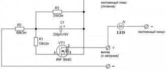
- voltage stabilization cascade.
The first stage is capacitance on capacitor C1 with a resistor. The resistor is necessary for self-discharge of the capacitor and does not affect the operation of the circuit itself. Its rating is not particularly critical and can be from 100 kOhm to 1 Mohm with a power of 0.5-1 W. The capacitor is necessarily non-electrolytic at 400-500V (effective peak voltage of the network).
In simple terms, only a tenth of the incoming voltage will pass through the capacitor.
The second stage is a diode bridge. It converts alternating voltage to direct voltage. After cutting off most of the half-wave voltage with a capacitor, we get about 20-24V DC at the output of the diode bridge.
The third stage is a smoothing stabilizing filter. A capacitor with a diode bridge acts as a voltage divider. When the voltage in the network changes, the amplitude at the output of the diode bridge will also change.
The assembled circuit of a 220-volt LED lamp begins to work immediately, but before connecting it to the network, carefully insulate all exposed wires and soldering points of circuit elements.
Driver option without current stabilizer
There are a huge number of driver circuits on the network for LEDs from a 220V network that do not have current stabilizers.
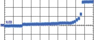
The problem with any transformerless driver is the ripple of the output voltage, and therefore the brightness of the LEDs. A capacitor installed after the diode bridge partially copes with this problem, but does not completely solve it.
There will be ripple on the diodes with an amplitude of 2-3V. When we install a 12V stabilizer in the circuit, even taking into account ripple, the amplitude of the incoming voltage will be higher than the cutoff range.
Voltage diagram in a circuit without a stabilizer
Diagram in a circuit with a stabilizer
Therefore, a driver for diode lamps, even one assembled with one’s own hands, will not be inferior in pulsation level to similar units of expensive factory-made lamps.
As you can see, assembling the driver with your own hands is not particularly difficult. By changing the parameters of the circuit elements, we can vary the output signal values within wide limits.
For more powerful lighting sources, it is necessary to either increase the number of output stages, or use a more powerful stabilizer with an output current of up to 5A and install it on a radiator.
Current converters for light diodes: where to buy and what is the cost
Such devices can be purchased at electrical stores or online resources. The second option is more affordable. In addition, many manufacturers offer free shipping. Let's consider some models with an input voltage of 220 V with technical characteristics and costs as of December 2017.
| Photo | Model | Protection class, IP | Output voltage, V | Power, W | Cost, rub. |
| DFT-I-40-LD64 | 20 | 60-130 | 45 | 400 | |
| ZF-AC LD49 | 40 | 40-70 | 54 | 450 | |
| XS0812-12W PS12 | 20 | 24-44 | 12 | 200 | |
| PS100 (open) | 20 | 30-36 | 100 | 1100 | |
| PF4050A PS50 | 65 | 27-36 | 50 | 500 | |
| PF100W LD100 | 65 | 23-36 | 100 | 1000 |
Looking at the prices, we can say that making a current converter yourself is more suitable for those for whom this is just a hobby. You can purchase such a device quite inexpensively.
You can use an old printed circuit board as a platform for self-assembly of the driver by connecting the contacts with wires
Summarize
When choosing a current converter for LED lamps, you should carefully calculate everything. Any error may lead to a reduction in the service life of the purchased device. Despite the low cost of the stabilizer, it is quite unpleasant to constantly throw money away. Only in this case will the driver serve its intended duration. And when making it yourself, follow the electrical safety rules and be careful and attentive when assembling the circuit.
We hope that the information provided today was useful to our reader. Any questions you may have can be asked in the discussion – we will definitely answer them. Write, ask, share your experience with other readers.
And finally, a short video on today's topic: