↑ Drive
It is necessary to move the milling cutter itself in 3 directions - XYZ, which means you need 3 drives - 3 motors with the transmission of rotation of the motor shaft into linear movement. About the transmission... For a milling machine where there are lateral forces cutting the material, it is advisable not to use belt drives, which are very popular in 3D printers. I will use a screw-nut transmission. The most budget-friendly gear is a regular steel screw and a backlash-free, preferably bronze, nut. A more correct one is a screw with a trapezoidal thread and a nut made of caprolon. The best (and, alas, most expensive) ball screw, or ball screw. I will talk about this in more detail later... Each gear has its own coefficient, its own pitch - that is, how linearly the milling cutter will move along the axis in one engine revolution, for example, by 4 mm.
↑ Engine (motor)
I chose a stepper motor (SM) as the motor for the drive. Why stepper?
What is this anyway? There are AC and DC motors, brushed and brushless, and so-called “stepping” motors. In any case, we need to ensure some positioning accuracy, for example 0.01 mm. How to do it? If the motor has a direct drive - the motor shaft is connected directly to the propeller, then to ensure such accuracy it is necessary to rotate it through a certain angle. In this case, with a gear pitch of 4 mm and a desired movement accuracy of 0.01 mm, this is... only 1/400 of a revolution, or 360/400 = 0.9 degrees! Nonsense, let’s take an ordinary motor... With a “ordinary” motor without feedback it will not work. Without going into too much detail, the motor control circuit needs to "know" what angle the axle has turned. You can, of course, install a gearbox - we will lose speed, and still there is no guarantee, no feedback at all! A rotation angle sensor is installed on the axle. This solution is reliable, but expensive.
An alternative is a stepper motor (read for yourself how it works). We can assume that in one “command” it will rotate its axis by a certain degree, usually 1.8 or 0.9 degrees (the accuracy is usually no worse than 5%) - just what is needed. The disadvantage of this solution is that under heavy load the engine will skip commands - “steps” and may stop altogether. The issue is resolved by installing a obviously powerful engine. Most amateur machines are made using stepper motors.
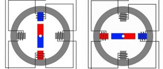
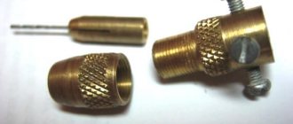
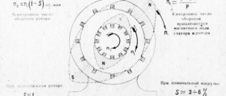
Comparison of two-phase and three-phase microstepping motors
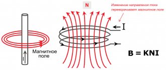
Stepper motors today are used in various fields: mechanical engineering, machine tool building, electronics and other types of activities. A stepper motor is a synchronous electric motor, the main elements of which are the stator, rotor and field windings. The rotor is set in motion by sequentially starting the windings, this leads to discrete angular displacement determined by the type and characteristics of the microstepping motor.
The microstepping mode is carried out by controlling the current of the windings of the microstepping motor. By choosing the values of the currents in the windings, you can fix the rotor in an intermediate position between steps. Due to this, the smooth running of the rotor increases and very high accuracy values can be achieved. Today, miraculous stepper motors make it possible to increase accuracy tens of times.
↑ Selecting a stepper motor
2 windings, with minimum current, minimum inductance and maximum torque - that is, the most powerful and economical motor.
Conflicting demands. Low current means high resistance, which means many turns of motor winding wire, which means high inductance. And a large torque means a large current and many turns. We choose in favor of higher current and lower inductance. And the moment must be chosen based on the load, but more on that later.
The characteristics of some engines are shown in the table:
For a small machine with a working space measuring 300x300x100 mm and a lightweight milling cutter, engines with a torque of 0.3 Nm and higher are quite suitable. The optimal current is from 1.5 to 2.5 Amps, FL42STH38-1684 is quite suitable
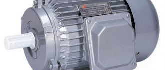
L298 + DC motors + Raspberry Pi
For this experiment, two DC motors were connected to the L298 module. The entire module is powered by one +6V battery.
Since this voltage is less than +12V (see description above), we leave the internal stabilizer jumper installed and additional +5V power supply is not required for the logic.
In this experiment, the “ ENA ” and “ ENB ” jumpers, which allow power to be supplied to the output bridges, are left installed - power will be supplied constantly to the output stages of the H-bridges of the L298 chip.
Thus, to control each of the motors we use the remaining four inputs: IN1, IN2, IN3, IN4.
After connecting the power, the LED on the module will light up, now we can apply +5V voltage to each of the inputs in turn and see how our engines will rotate.
Where can I get +5V? — in this case, this voltage is present on the power connector, on the right near GND. For the test, you can use a piece of wire - a jumper.
Now let's connect our module to the Raspberry Pi and write a simple test program in Python. To connect the control, I used the GPIO pins like this:
| Raspberry Pi GPIO | L298 module |
| Pin 7 (GPIO4) | IN1 |
| Pin 9 (GND) | GND (power connector) |
| Pin 11 (GPIO17) | IN2 |
| Pin 13 (GPIO27) | IN3 |
| Pin 15 (GPIO22) | IN4 |
Rice. 7. L298 + Raspberry Pi + DC motors.
My mini-computer is powered through a step-down switching stabilizer from a second +6V battery (for a raspberry you need +5V).
Let's move on to writing a program for our experiment. Our goal is to control the rotation of the shaft of each motor using a keyboard connected to the Raspberry Pi, or remotely via SSH, VNC.
But first, let's try a simple program in the Python scripting language, which will help you better understand how to control a DC motor.
We download the raspberry, open the Terminal or connect to it remotely using SSH. Create a new file and open it for editing using the command:
nano /home/pi/l298_dc_motors_test.py
We paste the Python script code into the editor, which is given below:
#!/usr/bin/env python # -*- coding: utf-8 -*- import time import RPi.GPIO as GPIO # Prepare GPIO pins. GPIO.cleanup() GPIO.setmode(GPIO.BCM) GPIO.setup(4, GPIO.OUT) GPIO.output(4, GPIO.LOW) GPIO.setup(17, GPIO.OUT) GPIO.output(17, GPIO .LOW) # Turn on the rotation of motor 1 in one direction. GPIO.output(4, GPIO.HIGH) # wait 5 seconds. time.sleep(5) # Turn off engine 1. GPIO.output(4, GPIO.LOW) # wait 10 seconds. time.sleep(10) # Turn on the rotation of motor 1 in the other direction. GPIO.output(17, GPIO.HIGH) # wait 5 seconds. time.sleep(5) # Turn off engine 1. GPIO.output(17, GPIO.LOW)
Exit the editor (CTRL+X) before confirming the writing of the contents to the file (press “Y” - yes). Make the script executable and run it:
chmod +x /home/pi/l298_dc_motors_test.py /home/pi/l298_dc_motors_test.py
After starting, one of the engines will begin to rotate in one direction for five seconds, then it will turn off and after waiting for 10 seconds, it will begin to rotate in the other direction for the next 5 seconds.
Below is a more complex and functional example of a program that will interact with the user and allow interactive control of two electric motors.
Similar to the first simplified script, the program can be saved in the same file or a new one can be created.
It is important that in this code example, indentation is respected; I have already written about this before here.
#!/usr/bin/env python # -*- coding: utf-8 -*- import os import sys import curses import time import RPi.GPIO as GPIO # Set the numbers of GPIO pins with which we will work M1_RIGHT = 4 M1_LEFT = 17 M2_RIGHT = 27 M2_LEFT = 22 # Function for preparing GPIO pins def setup(*ports): GPIO.cleanup() # Mode for naming pins by name, not by number on the board GPIO.setmode(GPIO.BCM) for port in ports : # Set pin to pin + low level "0" GPIO.setup(port, GPIO.OUT) GPIO.output(port, GPIO.LOW) # Function for setting low level on all pins (turn off) def stop_all(): GPIO .output(M1_LEFT, GPIO.LOW) GPIO.output(M1_RIGHT, GPIO.LOW) GPIO.output(M2_LEFT, GPIO.LOW) GPIO.output(M2_RIGHT, GPIO.LOW) # Function for controlling the rotation of motors def rotate(motor= 1, mode='s'): # Turn off all pins stop_all() # For motor 1 if motor == 1: if mode == 'r': # Set the M1_RIGHT pin to a high level (4) GPIO.output(M1_RIGHT, GPIO.HIGH) elif mode == 'l': # Set the M1_LEFT pin (17) to a high level GPIO.output(M1_LEFT, GPIO.HIGH) # For motor 2 elif motor == 2: if mode == 'r': GPIO.output(M2_RIGHT, GPIO.HIGH) elif mode == 'l': GPIO.output(M2_LEFT, GPIO.HIGH) # Initialize the pins GPIO setup(M1_RIGHT, M1_LEFT, M2_RIGHT, M2_LEFT) # Initialize the screen (curses module) stdscr = curses.initscr() # React to key presses without confirmation using ENTER curses.cbreak() # Allow the use of arrow keys on the keyboard stdscr.keypad(1) # Do not time out the program when polling events stdscr.nodelay(1) # Display the default data stdscr.addstr(0, 10, “Hit 'q' to quit”) stdscr.addstr(2, 10, “A - M1 Left, D - M1 Right”) stdscr.addstr(3, 10 , "< - M2 Left, > - M2 Right") stdscr.addstr(4, 10, "S - stop") stdscr.refresh() # Main loop while True: # Get the key press code and check it key = stdscr. getch() if key != -1: # If the key is “left arrow” then rotate slider 2 to the left if key == curses.KEY_LEFT: # Display the line “M2 <—” at position 6, 10 stdscr.addstr(6 , 10, “M2 <—“) rotate(2, 'l') # If the key is “right arrow” then rotate slider 2 to the right elif key == curses.KEY_RIGHT: stdscr.addstr(6, 10, “M2 ->” ) rotate(2, 'r') # If the key is "a" then rotate slider 1 to the left elif key == ord('a'): stdscr.addstr(6, 10, "M1 <—") rotate(1, ' l') # If the key is "d" then rotate slider 1 to the right elif key == ord('d'): stdscr.addstr(6, 10, "M1 ->") rotate(1, 'r') # If the key "s" then stops all engines elif key == ord('s'): stdscr.addstr(6, 10, "STOP 12") stop_all() # If the key is "s" then exit the program elif key == ord( 'q'): # Restore previous terminal settings stdscr.keypad(0) curses.echo() curses.endwin() # Clear and exit os.system('clear') sys.exit() # Update the text on the screen and do small delay stdscr.refresh() time.sleep(0.01)
Having launched the script, you can click the keyboard arrows “left” and “right”, as well as the keys with the letters “A” and “D” - the engines should rotate alternately and in different directions, and the program will display their current operating mode.
Rice. 8. Python program for controlling motors using the L298 driver (Konsole terminal, KDE).
A short video demonstration of this experiment is given below:
I would like to note that you can control the rotation speed of a DC electric motor shaft using pulse width modulation (PWM, PWM).
You can learn how to use this method for GPIO in the detailed article on the “RPi.GPIO” module.
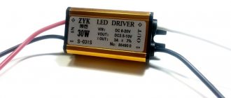
↑ Stepper motor driver
There is an engine.
Now we need a driver to switch the voltage on the motor windings in a certain way, without exceeding the set current. The simplest solution is a source of a given current and two pairs of transistor switches for each winding. And four protective diodes. And a logical circuit to change direction. And... This solution is usually made on the ULN2003A microcircuit for motors with low current, it has many disadvantages, I will not dwell on them.
An alternative is specialized all-in-one microcircuits - with logic, transistors and protection diodes inside (or outside). And such microcircuits control the current of the windings and regulate it using PWM, and can also implement the “half-step” mode, and some modes 1/4 step, and 1/8 step, etc. These modes can improve positioning accuracy , increase smoothness of movement and reduce resonance. Usually, the “half-step” mode is sufficient, which will increase the theoretical accuracy of linear positioning (in my example, up to 0.005 mm).
What's inside a stepper motor driver IC? Logic and control unit, power supplies, PWM with circuits for generating the torque and time of winding switching, output switches on field-effect transistors, feedback comparators - the current is controlled by the voltage drop across the resistors (Rs) in the power supply circuit of the windings. The motor current is set by the reference voltage.
To implement these functions, there are other circuit solutions, for example, using PIC or ATMEGA microcontrollers (again with external transistors and protection diodes). In my opinion, they do not have a significant advantage over “ready-made” microcircuits and I will not use them in this project.
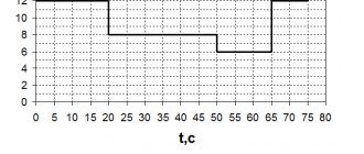
Smooth start and regulation of electric motor speed using timer NE555
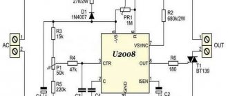
The frequency-setting circuit consists of C1 and R1, and the ratio is log. 1 and 0 – duty cycle – depends on the position of slider R1, more precisely, on the ratio of the resistances of the upper and lower parts of the resistor. These parts control the rate of charge or discharge of the capacitor, depending on the diode. When they are equal, the duration of the LED's glow and non-glow will be equal. In one of the extreme positions of the slider there will be a long glow with a short extinction time, in the other there will be short flashes.
On my own behalf, I will add that if the voltage on the 5th leg is equal to or greater than the supply voltage, the generation breaks down, the output is one, the key is completely open (which is what we need).
Let's look at real circuits. The very first serial circuit designed and manufactured using bipolar transistors. (The word “serial” means that I made more than 10 of them).
Below is the main serial diagram. Let's look at this in more detail. Provides smooth starting forward, reverse gear is engaged with a jerk. To save money, the customer agreed to this. The sound simulator was abandoned. The 55N06 field-effect transistors, ordered from China, were 20% defective, but the remaining ones worked so well (low losses and heating) that the RV was not immediately abandoned (parts K1, VD4, VT2, C5 and R5 were not installed). The intensity of acceleration is determined by capacitor C3 (from 1000.0 to 4700.0 μF) and resistor R1, the value was selected experimentally. It is not difficult to obtain a limit or the ability to adjust the speed; you need to connect a variable or trimming resistor with a nominal value of about 10...20 kOhm in parallel with C3, the slider of which is connected to the 5th leg of the timer.
↑ Wealth of choice
Today there are quite a lot of different microcircuits and quite a lot of ready-made boards and SD driver modules. You can buy a ready-made one, or you can “reinvent the wheel”, here everyone decides in their own way.
Of the ready-made ones, the most common and inexpensive drivers are based on Allegro A4988 (up to 2A) and Texas Instruments DRV8825 (up to 2.5A) chips. Since the modules were originally developed for use in 3D printers such as the Rep-rap project of the Arduino project, they are not complete modules (for example, they also need logic power (+5V), which is supplied from the so-called ramp).
There are also solutions based on DRV8811 (up to 1.9 A), A3982 (up to 2 A), A3977 (up to 2.5 A), DRV8818 (up to 2.5 A), DRV8825 (up to 2.5 A), Toshiba TB6560 (up to 3 A) and others.
Since I’m interested in doing something myself, plus the opportunity to “taste” the Allegro A3982 and A3977 microcircuits, I decided to make a couple of drivers myself.
I didn’t like the ready-made solutions on the A4988, primarily due to the miniaturization of the printed circuit board size at the expense of good cooling. The typical resistance of open transistors in the A4388 at a current of 1.5A is 0.32+0.43 Ohm, plus a 0.1-0.22 Ohm “measuring” resistor - it turns out to be about 0.85 Ohm. And there are two such channels, and although they operate pulsed, 2-3 Watts of heat must be dissipated. Well, I don’t believe in a multilayer board and a tiny cooling radiator - the datasheet shows a much larger board.
The motor wires must be kept short and the driver installed next to the motor. There are 2 technical solutions in audio engineering: a long signal cable to the amplifier + short wires to the speaker system, or a short signal cable to the amplifier + long wires to the speaker system. Both solutions have their pros and cons. It's the same with motors. I chose long control wires and short wires to the motor.
Control signals - “step” (step), “direction” (dir), “enable” (enable), indication of the state of control signals. Some circuits do not use the “Enable” signal, but this leads to unnecessary heating of both the chip and the motor in idle mode.
One power supply 12-24 volts, logic power supply (+5V) - on the board. The dimensions of the board are sufficient for good cooling, double-sided printing with a large “copper” area, the ability to glue a radiator onto the chip (used to cool the memory of video cards).
Audio amplifier with PWM timer 555
The widely used 555 PWM audio circuit uses the NE555 IC in astable mode, where the switching frequency can vary from 65 kHz to 188 kHz.
555 Timer PWM audio amplifier
Serial timer for DC motor control.
The sequential timer is a fairly commonly used circuit in industrial plants since most industrial processes are of the chain reaction type. This means that when one process completes, the next one starts.
Serial Timer for DC Motor Control Serial Timer Circuit for DC Motor Control
Contactless timer
An infrared contactless circuit of this type is also very often used as an electrical switch when physical contact is not desirable for hygiene reasons. For example, you can often see the use of infrared proximity sensors in public drinking fountains and public restrooms. The simple circuit shown here can be controlled by moving your hand in front of it. This is achieved by detecting infrared light reflected by your hand onto the receiving device.
Contactless Timer Switch
General purpose linear timer
This simple timer can be used to control any electrical appliance that needs to be turned off after a certain amount of time, provided the relay switch settings meet the requirements of that appliance. It is made from low-cost components and combines digital precision with simple analog control, providing long-lasting synchronization without the use of expensive resistors or capacitors.
Linear timer for general use
Infrared remote control timer.
Here is a circuit diagram of a timer with infrared remote control. The circuit consists of two sections, namely a transmitter section and a receiver section.
↑ Scheme and prototype
Designed in the DipTrace environment. The A3982 driver is included according to the diagram from the manufacturer's documentation. Half-step mode is enabled. Additionally, for reliable operation of control and indication signals, I used a 74NS14 logic chip (with Schmitt triggers). It was possible to make galvanic isolation using optocouplers, but for a small machine I decided not to do it. The circuit on the A3977 differs only in additional step mode jumpers and a more powerful power connector, but has not yet been implemented in hardware.
Domestic and foreign manufacturers
The 555 series timer chip is so popular that its analogues are manufactured by almost all well-known brands in the microelectronics industry. Moreover, they are geographically located not only in the USA, but also in other countries of the world. Among them: Texas Instrument, Sanyo, RCA, Raytheon, NTE Silvania, National, Motorola, Maxim, Lithic Systems, Intersil, Harris, Fairchild, Exar ECG Phillips and many others.
Often the series number from competitors contains a reference to the original NE555. There are markings NE555N, HE555P or the like.
Russian KR1006VI1
The timer is also produced in Russia, marked with the KR1006VI1 microcircuit with bipolar transistors and KR1441VI1 using CMOS technology. The national version is slightly different from the classic 555 series - in it the stop input has higher priority than the start signal.