Modern problems of electric drive development
The principle of designing mechanical systems by endowing them at the design stage with the ability to adapt to primary and power errors, to the transmitted power flow, must be laid down at the stage of developing the control system of any product.
The property of adaptation is inherent in biosystems and this property is a means of survival and evolution of biological systems; it consists in adapting to changing external conditions. Biosystems are equipped with receptors, are open, have many degrees of freedom and connections, and are capable of self-development. In the design of control systems, it is necessary to adhere to the principles of biological systems, improving and reducing them to the form of formulas and mathematics.
A modern electric drive is a complex symbiosis of an electric motor, a power current converter and a control system. The characteristics of the motor change depending on environmental conditions - the resistance of the stator windings and the electromechanical characteristics of the motor change, as a result of which the output parameters of the drive also change. To build a correct control algorithm, it is necessary to take into account many factors such as: ambient temperature, temperature of the stator windings, change in the active resistance of the stator windings, temperature drift of operational amplifiers in the current measurement circuit, motor rotor speed. To take into account external factors, it is necessary to complicate the hardware, which entails an increase in size and weight, a complication of the device as a whole, and, as a consequence, a decrease in its reliability. Therefore, it is necessary to strive for the most stable engine characteristics over the entire operating temperature range, but to minimize the parameters taken into account.
Stable torque characteristics of the engine under all operating conditions will reduce the safety margin in the executive structure and reduce weight. And the use of a minimum number of parameters taken into account will ensure an improvement in the overall dimensions and weight of the engine control unit and an increase in reliability. The stability of the drive to variable load torque is also important. To take into account all the criteria at the development stage, the control system is calculated. As well as mathematical modeling for analyzing the obtained data in all modes and operating conditions. Calculation of the control system and mathematical modeling of engine operation at the initial stage of drive development allows one to reliably select the characteristics of the engine and power converter for a specific task. Which in turn eliminates the cost of manufacturing unnecessary prototypes and testing them. The development and production time of a delivery sample of the product is also reduced. And time is most precious...
Correct calculation of the control system allows you to verify the relevance of the work being performed at the engine development stage and, if necessary, make changes to the designed product or its control system. And also to work out all the necessary options for the operation of the product, and develop adaptation algorithms to one way or another changing external factors.
The applications of brushless DC motors (BLDC motors) are continuously increasing. The reasons for this are the superior weight-to-power ratio of BLDC motors, their excellent acceleration characteristics, minimal maintenance costs, and the generation of low acoustic and electrical noise relative to universal (brushed) DC motors.
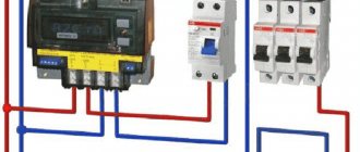
Since brushless motors are powered by alternating current, to operate they require a special controller (regulator) that converts direct current from the batteries into alternating current. Regulators for brushless motors are a programmable device that allows you to control all vital engine parameters. They allow you not only to change the speed and direction of operation of the motor, but also to provide, depending on the need, a smooth or sharp start, maximum current limitation, a “brake” function and a number of other fine engine settings.
There are a lot of manufacturers of brushless motors and regulators for them. Brushless motors also vary greatly in design and size. Moreover, self-manufacturing of brushless motors based on parts from CD drives and other industrial brushless motors has become quite common in recent years. Perhaps it is for this reason that brushless engines today do not even have such an approximate general classification as their brushed counterparts. Today, commutator motors are mainly used on inexpensive or entry-level models. These motors are inexpensive, easy to operate, and continue to be the most popular type of electric motor. They are being replaced by brushless motors. The only limiting factor so far remains their price. Together with the regulator, a brushless motor costs 30–70% more. However, prices for electronics and motors are falling, and the gradual displacement of brushed electric motors is only a matter of time.
The main problems in the development of electric drives are as follows:
‒ Engine performance varies depending on environmental conditions. The resistance of the stator windings and the electromechanical characteristics of the motor change, as a result of which the output parameters of the unit also change.
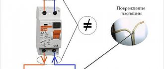
‒ For highly reliable units containing brushless DC motors, a redundant control system is required. A brushless motor requires a more complex control structure. Therefore, the number of electronic elements included in the product increases, as a result of which the reliability of the unit as a whole decreases.
‒ When the engine operates at high speeds, there is a fairly large jump in the generated torque when its sign changes to the opposite. This causes non-linearity of the control characteristics, resulting in a loss of accuracy in stabilizing the rotor speed and the developed torque.
In conclusion, I note that, despite the serious hardware support for vector PWM methods that has appeared in the latest microcontrollers, the workload for programmers has not decreased. They must still provide real-time: calculation of the base sector number and intra-sector angle; determining the components of the base vectors and reprogramming the PWM generator; correction of the influence of “dead” time and voltage losses on power switches; correction of voltage changes on the DC link. The listed tasks are solvable, which gives confidence in the possibility of quickly developing a new generation of promising digital drive control systems.
Literature:
- Directory. Control systems with digital regulators. V. I. Gostev, Kyiv, “Technology”, 1990
- Theory of automatic control systems. V. A. Besekersky, E. P. Popov, Nauka Publishing House, Moscow, 1975
- Main trends in the development of embedded motor control systems and requirements for microcontrollers. V. F. Kozachenko.
Electric drive (motor power selection)
⇐ PreviousPage 3 of 3The choice of motor is one of the critical stages in the design of an electric drive, since it is the motor that largely determines the technical and economic qualities of the drive as a whole. Of the numerous types of AC and DC motors to drive a particular production machine, one must be selected that most fully satisfies the technical and economic requirements. This means that the engine must be the easiest to control, reliable in operation and have the lowest cost, weight and dimensions, as well as high energy performance. In comparison with all existing types of motors, these requirements are best met by asynchronous motors with a squirrel-cage rotor. When choosing a motor of this type, it is necessary to find out whether the technical requirements are met: permissible reduction in speed when the load increases, permissible amount of repeated starts, possibility of quick and reliable starting.
In intense drive operating modes, with high switching frequencies, where increased or limited starting torque is required, as well as speed control within narrow limits, asynchronous motors with slip rings are used. For unregulated drives of medium and high power, operating in continuous mode with rare starts, it is recommended to use synchronous motors. They are characterized by higher efficiency. and allow power factor regulation through reactive power compensation. If smooth and deep speed control is necessary, as well as at high switching frequencies, DC motors are used.
When choosing engine power, the main initial data are the required torques that must be applied to the mechanism shaft, i.e. it is necessary to have load diagrams of the electric drive P=f(t) or M=f(t), which can be specified both in the form of a graph and in the form of a table.
An example of solving a problem on topic 4
.
Determine the required engine power to drive the mechanism, the operating mode of which is specified by the load diagram in Fig. 9. According to technological conditions, an asynchronous motor with a squirrel-cage rotor should be used. The engine must develop a rotation speed of n=980 rpm. The room where the engine will be installed is dry, free of dust and dirt.
Rice. 7. Load diagram
Solution.
In our case, the operating mode is a long-term variable load. The engine power is selected for similar operating modes based on the equivalent power, which is equal to
where tc is the work cycle time:
tc=t1+t2+t3=20+30+15=65 s;
kW
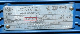
According to the catalog, an asynchronous squirrel-cage motor in a protected type A2-61-6 can be used as a drive motor; 380/220 V; Pn=10 kW, nn=965 rpm, hn=0.870, Mn/Mn=1.2, Mm/Mn=1.8.
In some cases, the load torque in certain areas may be greater than the maximum permissible motor torque, and the asynchronous motor may stop. Therefore, after selecting a motor, it must be checked for overload capacity based on the condition Mmax<Mmax.d, where Mmax is the maximum torque on the motor shaft; Mmax.d - maximum permissible motor torque. For an asynchronous motor Mmax.d=0.9·Mk. Here Mk is the critical (maximum) torque of the engine.
In our example: rated motor torque
Mn=9550Pn/nn=9550·10/965=99 N·m;
Maximum (critical) moment
Mk=l Mn=1.8·99=178 Nm;
Maximum static moment
Ms=9550·P1/n=9550·12/980=117 N·m.
The engine passes the overload capacity, since the condition 0.9·Mk=0.9·178=160>Ms=117 is met.
CONTROL TASKS
Task No. 1. For a three-phase transformer, the windings of which are connected in a star, and the values of rated power, rated voltages, short-circuit voltage, short-circuit power, no-load power and the ratio of no-load current to the rated current of the primary winding are given in Table 3, determine: rated current of the primary winding windings; no-load current; idle power factor; magnetic loss angle; short circuit resistance; resistance of the primary and secondary windings and resistance of the magnetizing circuit. Construct an external characteristic and a vector diagram at a load of b = 0.75 of the rated power of the transformer, and cos j2 = 0.8. Draw up a T-shaped substitution diagram.
Task No. 2. Three-phase asynchronous motor with a squirrel-cage rotor, the rated rotor speed of which is nн=1420 rpm, and the rated voltage, power, efficiency. , power factor, starting current multiplicity and overload capacity are given in Table 4, connected to the network with a frequency of f=50 Hz. Determine: rated and starting currents, rated, starting and maximum torques. Construct mechanical characteristics.
Task No. 3. For a parallel-excitation motor, information about the network voltage consumed at rated load and no-load current, the resistance of the armature winding and field circuit, as well as the rated rotation speed is given in Table 5, determine the rated power of the motor (on the shaft), the rated efficiency. d., rated torque, starting current when starting the engine without a starting rheostat, resistance of the starting rheostat for the condition Iп = 2.5I and starting torque when starting the engine with a rheostat. When deciding, assume that magnetic and mechanical losses do not depend on the load.
Task No. 4. For the load mode of the production mechanism specified in Table 6, construct a load diagram and select the power of an asynchronous squirrel-cage motor.
Literature
1. Bruskin D.E. and others. Electrical machines: In 2 parts. Part 1 /. D.E.Bruskin, A.E.Zorohovich, V.S.Khvostov. - M.: Higher. school, 1987.- - 319 p., (section 3).
2. Bruskin D.E. and others. Electrical machines: In 2 parts. Part 2 /. D.E.Bruskin, A.E.Zorohovich, V.S.Khvostov. - M.: Higher. school, 1987.- - 335 pp., (section 4).
3. Bashirin A., V., Novikov V.A., Sokolovsky G.G. Control of electric drives: Textbook for universities.-L.: Energoatomizdat, 1982.- 392 pp., (section 4).
4. Chilikin M.G., Sandler A.S. General electric drive course: Textbook for universities. - M.: Energoatomizdat, 1981 - 576 pp., (section 4).
5. Kopylov I.P. Mathematical modeling of electrical machines:
Educational for universities. - M.: Higher. school, 1987. - 248 pp., (sections 1,2).
6. Dombrovsky V.V., Zaichik V.M. Asynchronous machines. Theory, calculation, design elements.-L.: Energoatomizdat. 1990.- 358 p. , (section 3).
Applications
Table 3
Data for task 1 Table 3
| Option | Data for calculation | ||||
| Rated power kVA | Rated voltages | Short circuit voltage | Short circuit power | Idle power | Relative no-load current |
| 5,0 | 10,0 | ||||
| 5,0 | 9,0 | ||||
| 5,0 | 9,0 | ||||
| 5,0 | 8,0 | ||||
| 5,0 | 7,5 | ||||
| 5,0 | 7,5 | ||||
| 5,0 | 7,0 | ||||
| 5,0 | 7,0 | ||||
| 6,5 | 7,5 | ||||
| 5,5 | 6,5 | ||||
| 4,5 | 3,0 | ||||
| 4,7 | 3,0 | ||||
| 4,5 | 3,0 | ||||
| 4,7 | 3,0 | ||||
| 4,5 | 3,0 | ||||
| 4,5 | 3,0 | ||||
| 4,7 | 3,0 | ||||
| 4,0 | 3,2 | ||||
| 4,5 | 2,8 | ||||
| 4,5 | 2,8 | ||||
| 4,7 | 2,8 |
Table 4
| Option | kW | |||
| 0,8 | 0,75 | 0,86 | 2,2 | 7,0 |
| 0,1 | 0,795 | 0,87 | 2,2 | 7,0 |
| 1,5 | 0,805 | 0,88 | 2,2 | 7,0 |
| 2,2 | 0,83 | 0,89 | 2,2 | 7,0 |
| 3,0 | 0,845 | 0,89 | 2,2 | 7,0 |
| 4,0 | 0,855 | 0,89 | 2,2 | 7,0 |
| 5,5 | 0,86 | 0,89 | 2,2 | 7,0 |
| 7,5 | 0,87 | 0,89 | 2,2 | 7,0 |
| 0,88 | 0,89 | 2,2 | 7,0 | |
| 0,88 | 0,89 | 2,2 | 7,0 | |
| 0,88 | 0,90 | 2,2 | 7,0 | |
| 0,88 | 0,90 | 2,2 | 7,0 | |
| 0,89 | 0,90 | 2,2 | 7,0 | |
| 0,89 | 0,91 | 2,2 | 7,0 | |
| 0,90 | 0,92 | 2,2 | 7,0 | |
| 0,90 | 0,92 | 2,2 | 7,0 | |
| 0,915 | 0,92 | 2,2 | 7,0 |
Table 5
| Option | Data for calculation | |
| 1,6 | 1,2 | |
| 5,3 | 0,212 | |
| 6,5 | 0,11 | |
| 0,04 | 27,5 | |
| 16,3 | 1,78 | 1,16 |
| 7,8 | 0,7 | 0,8 |
| 19,8 | 2,0 | 1,5 |
| 3,2 | 0,6 | |
| 2,8 | 0,94 | |
| 3,0 | 0,45 | |
| 9,5 | 0,9 | 1,9 |
| 1,8 | 0,7 | |
| 1,5 | 0,82 | |
| 8,2 | 0,8 | 1,4 |
| 20,5 | 2,35 | 0,74 |
| 4,2 | 0,52 | |
| 10,5 | 1,2 | 1,2 |
| 18,6 | 2,0 | 0,9 |
| 1,8 | 0,6 | |
| 3,5 | 0,62 | |
| 3,2 | 0,55 | |
| 2,6 | 0,58 | |
| 6,8 | 0,40 | |
| 5,7 | 0,40 | |
| 9,5 | 0,12 | |
| 0,07 |
Table 6
| Option | R, kW | |||
| 13,5 | ||||
| 23,5 | ||||
| 1,5 | 2,5 | 1,5 | 1,5 | 3,5 |
| 1,5 | 2,5 | 3,5 | ||
| 23,5 | 3,5 | |||
| 3,0 | ||||
| 3,5 | ||||
| 1,5 | 2,5 | 1,5 | 1,5 | |
| 2,5 | 3,5 | |||
| 3,5 | ||||
| 23,5 |
⇐ Previous3
What will happen to the Earth if its axis shifts by 6666 km? What will happen to the Earth? - I asked myself...
Live by the rule: IS THERE NOT MUCH THING IN THE WORLD EXISTING? It is no coincidence that I emphasize that the space in your head is limited, but there is a lot of information around, and that your right...
What does the IS operation and maintenance department do? Responsible for the safety of data (copying schedules, copying, etc.)…
WHAT IS CONFIDENT BEHAVIOR IN INTERPERSONAL RELATIONSHIPS? Historically, there are three main patterns of differences that exist between...
Didn't find what you were looking for? Use Google search on the site: