The simplest schemes
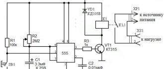
The first circuit is a simple probe
for testing electrical circuits. Using this probe, you can determine the reliability of electrical contact, find an open circuit, and check the serviceability of resistors and semiconductor diodes and transistors.
To assemble a radio-electronic device, you can pre-make a DIY KIT kit using the link.
Diagram of a probe for testing the continuity of an electrical circuit.
Let's describe his work. When the XT probes are open, a high logical voltage level is set at the inputs of the logical element DD1 relative to the common wire. Accordingly, the output of element DD1 will be a low logical level, while the LED VD1 will not light up. If the probes are connected to each other, then the DD1 input will have a low logic level, and the output will be high. A glowing diode will indicate that the outputs are closed to each other. Thus, when the probes are connected to a working circuit, the LED will light up, and if the LED does not light up, it means there is an open circuit in the circuit.
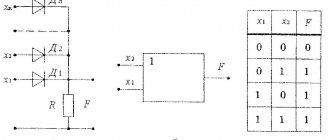
The following circuit shown below is a logic probe
.
It is intended to determine the logical voltage level in the electrical circuits of digital devices. Logic probe circuit.
In the initial state, a high logical level is set at the inputs of logic element DD1 and output DD2, and accordingly the LED VD1 is lit. When the LEDs are connected to a circuit with a high logical level, the VD1 LED continues to light, and when a low logical level appears at the DD1 input, the VD1 LED will go out accordingly.
Further narration about the use of digital microcircuits is not possible without knowledge of the internal structure
digital TTL and CMOS microcircuits and their
transfer characteristics
.
Add a link to a discussion of the article on the forum
RadioKot >Training >Digital technology >Basics of digital technology >
| Article tags: | Add a tag |
Digital microcircuits. Types of logic, enclosures
Author: Published 12/12/2005
Well, first let's say this: microcircuits are divided into two large types: analog and digital. Analog microcircuits work with an analog signal, and digital ones, respectively, with a digital one. We will talk specifically about digital microcircuits.
More precisely, we will not talk about microcircuits, but about elements of digital technology that can be “hidden” inside a microcircuit.
What are these elements?
Some names you have heard, some you may not. But believe me, these names can be pronounced out loud in any cultural society - these are absolutely decent words. So, an approximate list of what we will study:
- Triggers
- Counters
- Encryptors
- Decoders
- Multiplexers
- Comparators
- RAM
- ROM
All digital chips work with digital signals. What it is?
Digital signals are signals that have two stable levels - the logical zero level and the logical one level. For microcircuits made using different technologies, the logical levels may differ from each other.
Currently, the two most widely used technologies are TTL and CMOS.
TTL – Transistor-Transistor Logic; CMOS – Complementary Metal-Oxide-Semiconductor.
For TTL, the zero level is 0.4 V, the unity level is 2.4 V. For CMOS logic, the zero level is very close to zero volts, the unity level is approximately equal to the supply voltage.
In any case, one is when the voltage is high, zero when it is low.
BUT! Zero voltage at the output of the microcircuit does not mean that the output is “dangling in the air.” In fact, it is simply connected to the common wire. Therefore, you cannot directly connect several logical conclusions: if they have different levels, a short circuit will occur.
In addition to differences in signal levels, logic types also differ in power consumption, speed (maximum frequency), load capacity, etc.
The type of logic can be recognized by the name of the chip. More precisely, by the first letters of the name, which indicate which series the microcircuit belongs to. Within any series there may be microcircuits produced using only one technology. To make it easier for you to navigate, here is a small summary table:
| TTL | TTLSH | CMOS | Bastroaction. CMOS | ESL | |
| Explanation of the name | Transistor-Transistor Logic | TTL with Schottky diode | Complementary Metal Oxide Semiconductor | Emitter Matched Logic | |
| Main series of fatherland. microcircuits | K155 K131 | K555 K531 KR1533 | K561 K176 | KR1554 KR1564 | K500 KR1500 |
| Series of bourgeois microcircuits | 74 | 74LS 74ALS | CD40 H 4000 | 74AC 74HC | MC10 F100 |
| Propagation delay, nS | 10…30 | 4…20 | 15…50 | 3,5..5 | 0,5…2 |
| Max. frequency, MHz | 15 | 50..70 | 1…5 | 50…150 | 300…500 |
| Supply voltage, V | 5 ±0,5 | 5 ±0,5 | 3…15 | 2…6 | -5,2 ±0,5 |
| Current consumption (no load), mA | 20 | 4…40 | 0,002…0,1 | 0,002…0,1 | 0,4 |
| Level log.0, V | 0,4 | 0,5 | < 0,1 | < 0,1 | -1,65 |
| Level log. 1, V | 2,4 | 2,7 | ~U pit | ~U pit | -0,96 |
| Max. output current, mA | 16 | 20 | 0,5 | 75 | 40 |
The most common series today (and their imported analogues):
- TTLSH – K555, K1533
- CMOS – KR561, KR1554, KR1564
- ESL – K1500
It is recommended to build digital circuits using chips of only one type of logic. This is due precisely to differences in the logical levels of digital signals.
The type of logic is chosen mainly based on the following considerations:
— speed (operating frequency) — power consumption — cost
But there are situations where one type cannot be used. For example, one block should have low power consumption, and the other should have high speed. CMOS technology chips have low consumption. ESL has high speed.
In this case, you will need to install level converters.
True, some types fit together normally without converters. For example, a signal from the output of a CMOS microcircuit can be applied to the input of a TTL microcircuit (provided that their supply voltages are the same). However, it is not recommended to send a signal in the opposite direction, i.e., from TTL to CMOS.
Microcircuits are available in various packages. The most common types of enclosures are:
DIP (Dual Inline Package)
An ordinary "cockroach". We insert the legs into the holes on the board and solder them.
The legs in the body can be 8, 14, 16, 20, 24, 28, 32, 40, 48 or 56.
The distance between the terminals (pitch) is 2.5 mm (domestic standard) or 2.54 mm (for bourgeois).
Lead width approx. 0.5 mm
The numbering of the terminals is in the figure (top view). To determine the location of the first leg, you need to find a “key” on the body.
SOIC (Small Outline Integral Circuit)
Planar microcircuit - that is, the legs are soldered on the same side of the board where the body is located. In this case, the microcircuit lies on its belly on the board.
The number of legs and their numbering are the same as for DIP.
Lead pitch is 1.25 mm (domestic) or 1.27 mm (bourgeois).
Lead width – 0.33…0.51
PLCC (Plastic J-leaded Chip Carrier)
Square (less often rectangular) body. The legs are located on all four sides, and have a J-shape (the ends of the legs are bent under the abdomen).
The microcircuits are either soldered directly onto the board (planar) or inserted into the socket. The latter is preferable.
Number of legs – 20, 28, 32, 44, 52, 68, 84.
Leg pitch – 1.27 mm
Lead width – 0.66…0.82
Pin numbering - the first leg near the key, increasing the number counterclockwise:
TQFP (Thin Quad Flat Package)
Something between SOIC and PLCC.
The square case is about 1mm thick, the terminals are located on all sides.
The number of legs is from 32 to 144.
Pitch – 0.8 mm
Lead width – 0.3…0.45 mm
Numbering is from the beveled corner (top left) counterclockwise.
This is how things stand, in general terms, with buildings. I hope now it will become a little easier for you to navigate the countless number of modern microcircuits, and you will not be driven into a stupor by a phrase from the seller like: “this microcircuit is only available in the PE EL SI SI package”...
<<—Let’s remember what we’ve covered—Let’s move on—>>
| What do you think of this article? | Did this device work for you? | |
| 49 | 1 | 0 |
| 1 | 0 |
Internal structure of TTL digital chips
All families of digital chips are based on basic logic elements
.
For all microcircuits of the TTL family, such an element is the 2I-NOT element
, which has the following internal structure.
Below is shown the diagram of the 2I-NOT element and its transient characteristic. The diagram of the basic TTL 2I-NOT element and its transient characteristic.
a multi-emitter transistor at the input of the element
VT1, then
an amplifier stage
on transistor VT2 and
a push-pull output stage
on transistors VT3, VT4.
Let us describe the operation of the 2I-NOT logic element. In the initial state, the input voltage does not exceed 0.5 V, and the emitter junction of transistor VT1 is open, this voltage is not enough to transfer the collector junction to the open state, the same applies to the emitter junctions of transistors VT2, VT4. Therefore, these transistors are closed, and transistor VT3 is open, by the voltage coming from R2. Diode VD3 turns out to be open and the voltage at the output of the element is approximately 3...4 V ( point A
).
When the voltage on the emitters of VT1 begins to increase, transistor VT2 begins to open, and transistor VT3 smoothly closes ( section A - B
).
A further increase in the voltage on the input transistor leads to the fact that transistor VT2 opens even more, the voltage on R3 also increases and transistor VT4 opens. As a result, the emitter junction of transistor VT4 bypasses resistor R3, and transistor VT2 opens sharply, and the voltage at the output of the element decreases. At this moment ( section B - C
) all transistors are open and in active mode.
If you continue to increase the input voltage, then transistors VT2 and VT4 will go into saturation mode ( section B - D
), and transistor VT3 will close and the output voltage value will become equal to the saturation voltage of transistor VT4, and the current will be limited by resistor R4.
Section B – C
The transient response can be used
to process analog signals
; in this mode, the transient response has high linearity and maximum power consumption.
World market[ | ]
In 2022, the global integrated circuit market was estimated at $700 billion.[24]
The main producers and exporters are in Asia: Singapore ($115 billion), South Korea ($104 billion), China ($80.1 billion) and Malaysia ($55.7 billion). The largest European exporter is Germany ($1.4 billion), the American exporter is the USA ($28.9 billion). The largest importers: China ($207 billion), Hong Kong ($168 billion), Singapore ($57.8 billion), South Korea ($38.6 billion) and Malaysia ($37.3 billion).
Internal design of CMOS digital chips
Just like in the TTL family, the basic element of CMOS microcircuits is 2I-NOT
, the internal structure of which is shown below.
Diagram of the basic 2I-NOT CMOS element and its transient response.
Complementary field-effect transistors operate in this logic element
.
Transistors with a p-type channel (VT1, VT2)
are connected to the positive conductor of the power source,
and with an n-type channel (VT3, VT4)
they are connected in series.
At an input voltage of 2 V or less, transistors VT1 and VT2 are open, since the voltage in the gate-source sections (with a supply voltage of 9 V) is at least 7 V. The voltage in the same sections of transistors VT3 and VT4 is insufficient to open them, therefore at the output of the element there will be a voltage almost equal to the supply voltage, that is, about 9 V ( point A
).
As the input voltage increases, the transistors begin to open, and VT1 and VT2 begin to close. In section A - B
this process occurs relatively smoothly, and in
section B - C
it accelerates and is most linear.
At point B,
transistors VT1 and VT2 are almost completely closed, and VT3 and VT4 are open.
The output voltage in this case is small and with a further increase in the input voltage to the level of the power source, it tends to zero ( point G
).
Chip series[ | ]
Main article: Chipset
Analog and digital microcircuits are produced in series. A series is a group of microcircuits that have a single design and technological design and are intended for joint use. Microcircuits of the same series, as a rule, have the same power supply voltages and are matched in terms of input and output resistances and signal levels.
Cases[ | ]
Surface Mount IC Packages
Main article: Types of IC Packages
Microassembly with an open-frame microcircuit welded onto a printed circuit board
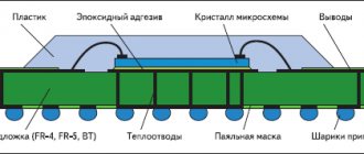
The microcircuit housing is a structure designed to protect the microcircuit crystal from external influences, as well as for ease of installation of the microcircuit into an electronic circuit. It contains the housing itself made of dielectric material (plastic, less often ceramic), a set of conductors for electrically connecting the crystal with external circuits through leads, and markings.
There are many options for microcircuit packages, differing in the number of microcircuit pins, installation method, and operating conditions. To simplify installation technology, chip manufacturers are trying to unify packages by developing international standards.
Sometimes microcircuits are produced in an unpackaged design - that is, a crystal without protection. Packless microcircuits are usually designed for installation in a hybrid microassembly. For mass-produced cheap products, direct mounting on a printed circuit board is possible.
Specific names[ | ]
Intel company
was the first to produce a microcircuit that performed the functions of a microprocessor (English microprocessor) -
Intel
4004. Based on the improved microprocessors 8088 and 8086, IBM
released
its famous personal computers.
The microprocessor forms the core of the computer; additional functions, such as communication with peripherals, were performed using specially designed chipsets (chipset). For the first computers, the number of microcircuits in sets was in the tens and hundreds; in modern systems it is a set of one, two or three microcircuits. Recently, there have been trends in the gradual transfer of chipset functions (memory controller, PCI Express
) to the processor.
Microprocessors with built-in RAM and ROM, memory and I/O controllers, and other additional functions are called microcontrollers.
Logic element in linear mode
The use of logical elements of digital microcircuits to work with analog signals is possible only if their mode is set to linear
or close to it.
So in linear mode, a TTL element
is equivalent to an amplifier with a gain of 10 ... 15 (approximately 20 dB), and
a CMOS element
is equivalent to an amplifier with a gain of 10 ... 20 (20 ... 26 dB).
Output of a logical element into linear mode: from left to right by current, voltage, feedback.
Various methods are used to output a logical element to a linear section. One of them is based on the inclusion of resistor R at the input of the TTL element
.
This resistor will cause a current to flow through the emitter junction of the TTL element's input transistor. By changing the resistance of the external resistor, you can change the voltage at the output of the element, that is, change the position of its operating point on the transfer characteristic. For TTL elements,
the resistance of such an external resistor ranges from 1 kOhm to 3 kOhm.
However, this method is not applicable for CMOS microcircuits
, since they operate without output currents (there are leakage currents, but they are small and unstable).
The second way to bring a logic element into operating mode can be by applying the appropriate voltage to the input
, for example using
a resistive divider
.
Thus, for TTL elements
the middle of the linear section of the transfer characteristic corresponds to
an input voltage of 1.5...1.8 V
, and for
CMOS 3...6 V
(with a supply voltage of 9 V). For different logic elements this voltage is not the same, so it is selected experimentally. The values of the input resistors are chosen in such a way that the input currents of the elements do not affect the voltage removed from the resistive divider.
The third method is the most effective, for this they create negative feedback (NF)
by direct current between the input and output of the element, due to which the operating point is automatically maintained at the required portion of the transfer characteristic and does not require careful selection of external resistors.
This method is implemented for logic elements with inversion
of the input signal: NOT, NAND, NOR.
resistance in the OOS circuit
are selected based on providing the element with the required input current.
For CMOS elements
it ranges
from several kiloohms to tens of megaohms
, and for
TTL – from tens of ohms to 1 kOhm
. But the use of OOS reduces the gain of the element.
Design levels[ | ]
- topological - topological photomasks for production[8]
- physical - methods of implementing one transistor (or a small group) in the form of doped zones on a chip
- electrical - circuit diagram (transistors, capacitors, resistors, etc.)
- circuit and system level - circuit and system design (flip-flops, comparators, encoders, decoders, ALUs, etc.)
- logical - logic circuit (logical inverters, OR-NOT, AND-NOT elements, etc.)
- software - allows the programmer to program (for FPGAs, microcontrollers and microprocessors) the model being developed using a virtual circuit
Currently (2014), most integrated circuits are designed using specialized CAD systems, which make it possible to automate and significantly speed up production processes, for example, obtaining topological photomasks.
Logic amplifiers
To use logic elements as signal amplifiers, it is necessary to bring the operating point to the linear section of the transfer characteristic. The main characteristics of such amplifiers are shown in the table below.
| Series | Output circuit to linear mode | SUS, dB | Fmax, MHz | Rinput mW | Uout, V | Rin, kOhm | Rout, kOhm | R1, kOhm | R2, kOhm |
| K155 | OOC | 18 | 40 | 20 | 1,2 | 0,6 | 0,05 | 0,68 | 0,68 |
| Current | 21 | 0,8 | 1,9 | — | |||||
| K176 | OOC | 25 | 5,5 | 5 … 20 | 1,5 | 0,4 | 0,05 | 7,5 | 5,1 |
| Current | 17 | 3 … 4 | 5,0 | 3,5 | 6 | 6,2 | 4 | ||
| 561 | OOC | 25 | 1000 | 7 | 1000 | 1000 |
The circuit of the simplest amplifier based on a TTL element is shown below. Adjusting the amplifier comes down to setting the operating point of the element with the trimming resistor R1 in the middle of the linear section of the transfer characteristic.
The simplest amplifier based on a TTL element
The disadvantage of simple amplifiers is their low input impedance
, which limits their scope of application. In addition, the gain is small. This disadvantage is eliminated by using it in conjunction with transistors. The gain is increased by connecting several stages in series. In addition, the digital chip contains several identical elements, which makes it possible to create multi-channel amplifiers. An example is the diagram shown below. Main characteristics of the amplifier: gain – 50; output impedance 50 Ohm, input impedance 5 kOhm, upper limit frequency 40 MHz.
Amplifier circuit with a transistor at the input
CMOS elements can also be used for amplifiers, the circuit of one of them is shown below. A common disadvantage of CMOS amplifiers is high output impedance.
.
It can be eliminated by installing an emitter follower
on a transistor at the output of the logic element and connecting it to the OOS circuit.
Amplifier circuits based on CMOS elements.
Threshold devices based on logic elements
Threshold devices
, called comparators, are designed to convert an analog signal into digital information.
The simplest threshold device is the Schmitt trigger, which is described in this post. In addition to generating pulses and restoring digital signals, threshold devices are used in analog-to-digital converters and pulse generators of various shapes. Diagram of a threshold device based on logical elements.
By and large, the logical element is itself a threshold device, but its transfer characteristic
not entirely linear.
To increase the linearity of the transfer characteristic of a logic element, it must be covered by positive feedback (POF)
for direct current through resistor R2.
In this case, it turns into a kind of Schmitt trigger
with the ability to regulate threshold voltages.
The width of the hysteresis loop
(the difference between the threshold voltages) depends on the ratio of the values of resistors R1 and R2.
Sensitivity also depends on these resistors. As R2 increases and R1 decreases, sensitivity increases and the width of the hysteresis loop decreases. For TTL microcircuits,
resistance R1 = 0.1 ... 2 kOhm, and R2 = 2 ... 10 kOhm.
Threshold devices based on CMOS elements are highly economical, but the disadvantage is low sensitivity. For CMOS chips,
R1 is several tens of kilo-ohms, and R2 is several hundred kilo-ohms.