Dmitry Levkin
- Three-phase squirrel-cage induction motor Design of an asynchronous electric motor
- Operating principle of a three-phase motor
- Slip of induction motor
- Three-phase alternating current
- Direct connection to mains power
- Three-phase asynchronous motor with wound rotor Design features
- Designation of rotor terminals
- Start ADFR
Three-phase asynchronous electric motor
is an asynchronous electric motor that has a three-phase stator winding.
Three-phase squirrel-cage asynchronous motor
Squirrel-cage induction motor
is an asynchronous electric motor whose rotor is made with a short-circuited winding in the form of a squirrel cage [1].
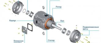
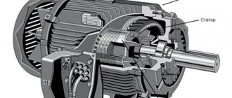
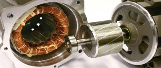
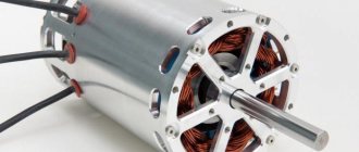
Construction of an asynchronous electric motor
A three-phase asynchronous electric motor, like any electric motor, consists of two main parts - a stator and a rotor. The stator is the stationary part, the rotor is the rotating part. The rotor is placed inside the stator. There is a small distance between the rotor and stator, called an air gap, usually 0.5-2 mm.
Asynchronous motor stator
Asynchronous motor rotor
Stator
consists of a body and a core with a winding.
The stator core is assembled from thin sheet technical steel, usually 0.5 mm thick, coated with insulating varnish. The laminated core design contributes to a significant reduction in eddy currents arising during the process of magnetization reversal of the core by a rotating magnetic field. The stator windings are located in the slots of the core. Housing and stator core of an asynchronous electric motor
Construction of a laminated core of an asynchronous motor
Rotor
consists of a core with a short-circuited winding and a shaft. The rotor core also has a laminated design. In this case, the rotor sheets are not varnished, since the current has a low frequency and the oxide film is sufficient to limit eddy currents.
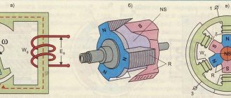
Principle of operation. Rotating magnetic field
The operating principle of a three-phase asynchronous electric motor is based on the ability of a three-phase winding to create a rotating magnetic field when connected to a three-phase current network.
A rotating magnetic field is the basic concept of electric motors and generators.
Launch
Stop
Rotating magnetic field of an asynchronous electric motor
The rotation frequency of this field, or the synchronous rotation frequency, is directly proportional to the frequency of the alternating current f1 and inversely proportional to the number of pole pairs p of the three-phase winding.
,
- where n1 is the rotation frequency of the stator magnetic field, rpm,
- f1 – alternating current frequency, Hz,
- p – number of pole pairs
Rotating magnetic field concept
To understand the rotating magnetic field phenomenon better, consider a simplified three-phase winding with three turns. Current flowing through a conductor creates a magnetic field around it. The figure below shows the field created by three-phase alternating current at a specific point in time
Launch
Stop
Magnetic field of a straight conductor with direct current
Magnetic field created by the winding
The components of alternating current will change over time, causing the magnetic field they create to change. In this case, the resulting magnetic field of the three-phase winding will take different orientations, while maintaining the same amplitude.
Magnetic field created by three-phase current at different times Current flowing in the turns of the electric motor (60° shift)
Launch
Stop
Rotating magnetic field
The effect of a rotating magnetic field on a closed loop
Now let's place a closed conductor inside a rotating magnetic field. According to the law of electromagnetic induction, a changing magnetic field will give rise to an electromotive force (EMF) in the conductor. In turn, the EMF will cause a current in the conductor. Thus, in a magnetic field there will be a closed conductor with a current, on which, according to Ampere’s law, a force will act, as a result of which the circuit will begin to rotate.
The influence of a rotating magnetic field on a closed conductor carrying current
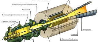
Squirrel-cage rotor of an asynchronous motor
An asynchronous electric motor also operates on this principle. Instead of a current-carrying frame, inside the asynchronous motor there is a squirrel-cage rotor whose design resembles a squirrel wheel. A squirrel-cage rotor consists of rods short-circuited at the ends with rings.
Squirrel cage rotor most widely used in induction motors (shown without shaft and core)
Three-phase alternating current, passing through the stator windings, creates a rotating magnetic field. Thus, also as described earlier, a current will be induced in the rotor bars, causing the rotor to start rotating. In the figure below you can notice the difference between the induced currents in the rods. This occurs due to the fact that the magnitude of the change in the magnetic field differs in different pairs of rods, due to their different locations relative to the field. The change in current in the rods will change with time.
Launch
Stop
Rotating magnetic field penetrating a squirrel-cage rotor
Magnetic moment acting on the rotor
You may also notice that the rotor arms are tilted relative to the axis of rotation. This is done in order to reduce the higher harmonics of the EMF and get rid of torque ripple. If the rods were directed along the axis of rotation, then a pulsating magnetic field would arise in them due to the fact that the magnetic resistance of the winding is much higher than the magnetic resistance of the stator teeth.
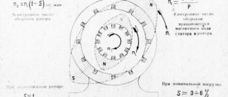
Slip of an asynchronous motor. Rotor speed
A distinctive feature of an asynchronous motor is that the rotor speed n2 is less than the synchronous speed of the stator magnetic field n1.
This is explained by the fact that the EMF in the rotor winding rods is induced only when the rotation frequencies n21 are unequal. The rotation frequency of the stator field relative to the rotor is determined by the sliding frequency ns=n1-n2. The lag of the rotor from the rotating field of the stator is characterized by a relative value s called slip:
,
- where s is the slip of an asynchronous electric motor,
- n1 – rotation frequency of the stator magnetic field, rpm,
- n2 – rotor speed, rpm,
Let us consider the case when the rotor rotation frequency coincides with the rotation frequency of the stator magnetic field. In this case, the relative magnetic field of the rotor will be constant, thus no EMF, and therefore no current, will be created in the rotor rods. This means that the force acting on the rotor will be zero. This will slow down the rotor. After which an alternating magnetic field will again act on the rotor rods, thus the induced current and force will increase. In reality, the rotor of an asynchronous electric motor will never reach the rotation speed of the stator magnetic field. The rotor will rotate at a certain speed which is slightly less than the synchronous speed.
The slip of an asynchronous motor can vary in the range from 0 to 1, i.e. 0-100%. If s~0, then this corresponds to the idle mode, when the engine rotor experiences practically no counteracting torque; if s=1 - short circuit mode, in which the motor rotor is stationary (n2 = 0). Slip depends on the mechanical load on the motor shaft and increases with its growth.
The slip corresponding to the rated load of the motor is called rated slip. For low and medium power asynchronous motors, the rated slip varies from 8% to 2%.
Energy conversion
An asynchronous motor converts electrical energy supplied to the stator windings into mechanical energy (rotation of the rotor shaft). But the input and output power are not equal to each other since energy losses occur during conversion: friction, heating, eddy currents and hysteresis losses. This energy is dissipated as heat. Therefore, an asynchronous electric motor has a fan for cooling.
Engineer's world
Greetings, dear and respected reader of the site “world-engineer.ru”. In one of the articles devoted to electric ball valves, I raised the issue of the operation of an asynchronous motor and promised to talk about it in another article. So in this article you will learn the working principle of an induction motor.
An asynchronous motor is designed to operate in a continuous operating mode (symbol S1), in which the load applied to the shaft and the cooling conditions of the motor are practically constant for a period of time sufficient to heat the motor to a steady temperature.
Correct calculation of average values of efficiency and power factor is especially important when choosing geometric dimensions, calculating losses, heating and cooling, and choosing the installed power of standard engines used for operation in short-term and intermittent modes.
For asynchronous motors, the set of short-term, intermittent and intermittent operating modes is divided into 7 groups with symbols S2...S8.
Short-term mode (S2), a mode in which the engine does not have time to reach the nominal temperature of the heating parts during operation at a constant load, and manages to cool down to ambient temperature during pauses.
The intermittent mode (S3) of operation of an asynchronous motor is typical for operating conditions in which the cycle duration (10 min) is much longer than the start time (i.e., the transient process during start-up does not affect the heating of the engine and is not taken into account). The duration of working time during the cycle is set as a percentage of the cycle time 5%, 25%, 40% and 60%.
In modes (S4), in contrast to (S3), the cycle duration is so short that the processes occurring during start-up (increase in losses due to multiple excess of starting currents above the rated value) have a direct impact on the heating of the machine. The cycle duration, in this case, is determined by the duration of working time as a percentage of the cycle time and the number of starts per hour. Since the nature of the transient process is largely determined by the dynamic load on the shaft, the permissible coefficient of inertia is additionally set (the ratio of the sum of the moments of inertia of the rotor and the moment of inertia of the drive mechanism reduced to the rotor rotation speed, to the moment of inertia of the rotor), for which the engine is designed under normal heating conditions.
The operating modes of an asynchronous motor, in which electrical braking of the motor is provided at the end of each cycle, are designated (S5). The duration of activation in this case is calculated taking into account the electric braking time.
The intermittent mode (S6) repeats the operating conditions of the mode (S3), taking into account the fact that in this mode reverse with electrical braking or transition to another rotation speed is allowed. Starting losses due to engine heating are not taken into account.
The intermittent mode (S7) repeats the operating conditions of mode (S4), taking into account the fact that in this mode reverse with electrical braking or transition to another rotation speed is allowed.
The intermittent mode (S8) repeats the operating conditions of the mode (S7), taking into account the fact that in this mode the engine can operate at several different rotation speeds with different load values on the shaft.
Features of determining installed power in short-term (S2) and intermittent operating modes (S3, S6)
In short-term (S2) and intermittent operating modes (S3, S6), electric motors can operate with higher installed power than in long-term operating mode (S1).
The possible value of the excess power is recommended to be determined from the condition of maintaining the overload capacity of the asynchronous motor for maximum torque within the limits:
MKR / (MN*KP) >= 1.6
For large switching numbers and large flywheel masses, it is recommended to determine power based on:
- relative duration of switching on;
- switching frequency;
- the magnitude of the external moment of inertia;
- drive load diagram;
- type of braking.
Recommended coefficients for exceeding installed power
| S2 | Excess factor | S3 | Excess factor | S6 | Excess factor |
| 10 min | 1,4 | 25% | 1,33 | 25% | 1,45 |
| 30 min | 1,15 | 40% | 1,18 | 40% | 1,35 |
| 60% | 1,08 | 60% | 1,15 |
Currently, GOST 183-74 Electrical rotating machines has been cancelled. General technical conditions. And now, instead of this GOST, GOST R 52776-2007 (IEC 60034-1-2004) Rotating electric machines is in force. Nominal data and characteristics.
According to the current GOST, the operating mode of an asynchronous motor (electric machines) is selected from standard modes from S1 to S10:
S1 – continuous mode. Operation of an asynchronous motor with constant load and duration;
S2 – short-term mode. Operation of an asynchronous motor with a constant load for a certain time. Designation option S2 60 min;
S3 – intermittent periodic mode. Operation of an asynchronous motor under successive identical operating cycles. Designation option S3 25%;
S4 – intermittent periodic mode with starts;
S5 - intermittent periodic mode with electric braking;
S6 - continuous periodic mode with short-term load;
S7 - continuous periodic mode with electric braking;
S8 - continuous periodic mode with interdependent changes in load and rotation speed;
S9 - mode with non-periodic changes in load and rotation speed;
S10 - mode with discrete constant loads and rotation speeds.
More detailed information can be found in GOST R 52776-2007 (IEC 60034-1-2004) Rotating electrical machines. Nominal data and characteristics.
Share link:
Connecting an asynchronous motor
Three-phase alternating current
The three-phase alternating current electrical network is the most widely used among electrical energy transmission systems. The main advantage of a three-phase system compared to single-phase and two-phase systems is its cost-effectiveness. In a three-phase circuit, energy is transmitted through three wires, and the currents flowing in different wires are phase-shifted relative to each other by 120°, while the sinusoidal EMFs at different phases have the same frequency and amplitude.
Three-phase current (phase difference 120°)
Star and triangle
The three-phase stator winding of the electric motor is connected in a star or delta configuration, depending on the network supply voltage. The ends of a three-phase winding can be: connected inside the electric motor (three wires come out of the motor), brought out (six wires come out), brought into a distribution box (six wires come out of the box, three wires come out of the box).
Phase voltage
- potential difference between the beginning and end of one phase. Another definition for a star connection is that the phase voltage is the potential difference between the line wire and the neutral (note that the delta connection does not have a neutral).
Line voltage
- potential difference between two linear wires (between phases).
| Star | Triangle | Designation |
| Uл, Uф - linear and phase voltage, V, | ||
| Il, Iph - linear and phase current, A, | ||
| S — total power, W | ||
| P—active power, W |
Attention: Although the power for star and delta connections is calculated using the same formula, connecting the same motor in different ways to the same electrical network will result in different power consumption. In this case, incorrect connection of the electric motor can lead to melting of the stator windings.
Example: Let’s say the electric motor was connected in a star configuration to a three-phase alternating current network Ul=380 V (respectively Uph=220 V) and consumed current Il=1 A. Total power consumption: S = 1.73∙380∙1 = 658 Tue
Now let’s change the connection diagram to a “triangle”, the linear voltage will remain the same Uл=380 V, and the phase voltage will increase by the root of 3 times Uф=Uл=380 V. An increase in the phase voltage will lead to an increase in the phase current by the root of 3 times. Thus, the linear current of the delta circuit will be three times greater than the linear current of the star circuit. And therefore the power consumption will be 3 times greater:
S = 1.73∙380∙3 = 1975 W.
Thus, if the motor is designed to be connected to a three-phase AC network in a star configuration, connecting this electric motor in a delta configuration may lead to its failure.
If in normal mode the electric motor is connected in a delta circuit, then to reduce the starting currents during the start-up it can be connected in a star circuit. In this case, along with the starting current, the starting torque will also decrease.
Connecting an electric motor according to a star and delta circuit
Designation of the stator terminals of a three-phase electric motor
Designation of the terminals of the stator windings of newly developed
three-phase machines according to
GOST 26772-85
[2]
| Winding connection diagram, name of phase and output | Pin designation | |
| Start | End | |
| Open circuit (number of pins 6) | ||
| first phase | U1 | U2 |
| second phase | V1 | V2 |
| third phase | W1 | W2 |
| Star connection (number of pins 3 or 4) | ||
| first phase | U | |
| second phase | V | |
| third phase | W | |
| star point (zero point) | N | |
| Delta connection (number of pins 3) | ||
| first conclusion | U | |
| second conclusion | V | |
| third conclusion | W | |
previously developed stator winding terminals
and modernized three-phase machines in accordance with
GOST 26772-85
| Winding connection diagram, name of phase and output | Pin designation | |
| Start | End | |
| Open circuit (number of pins 6) | ||
| first phase | C1 | C4 |
| second phase | C2 | C5 |
| third phase | C3 | C6 |
| Star connection (number of pins 3 or 4) | ||
| first phase | C1 | |
| second phase | C2 | |
| third phase | C3 | |
| zero point | 0 | |
| Delta connection (number of pins 3) | ||
| first conclusion | C1 | |
| second conclusion | C2 | |
| third conclusion | C3 | |
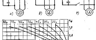
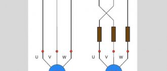
Connecting a three-phase asynchronous motor to a single-phase network using a phase-shifting element
Three-phase asynchronous electric motors can be connected to a single-phase network using phase-shifting elements. In this case, the electric motor will operate either in the mode of a single-phase motor with a starting winding (Figure a, b, d) or in the mode of a capacitor motor with a constantly switched on working capacitor (Figure c, e, f).
Connection diagrams for a three-phase asynchronous electric motor to a single-phase network
The diagrams shown in Figure “a”, “b”, “d” are used when all six ends of the winding are brought out. Electric motors with winding connections according to diagrams “a”, “b”, “d” are almost equivalent to motors that are designed as single-phase electric motors with a starting winding. The rated power is 40-50% of the power in three-phase mode, and when working with a working capacitor it is 75-80%.
The capacity of the working capacitor at a current frequency of 50 Hz for circuits “c”, “d”, “f” is approximately calculated accordingly according to the formulas:
- ,where Crab is the capacitance of the working capacitor, μF,
- Inom – rated (phase) stator current of a three-phase motor, A,
- U1 – single-phase network voltage, V.
If the rotor of an asynchronous machine connected to a network with voltage U1 is rotated by means of a prime mover in the direction of the rotating stator field, but with a speed n2>n1, then the movement of the rotor relative to the stator field will change (compared to the motor mode of this machine), since the rotor will overtake the stator field.
In this case, the slip will become negative, and the direction of the emf. E1 induced in the stator winding, and therefore the direction of current I1 will change to the opposite. As a result, the electromagnetic torque on the rotor will also change direction and from rotating (in motor mode) will turn into counteracting (in relation to the torque of the prime mover). Under these conditions, the asynchronous machine will switch from motor to generator mode, converting the mechanical energy of the primary engine into electrical energy. In the generator mode of an asynchronous machine, slip can vary in the range − ∞ < s < 0, while the frequency of the emf. of the asynchronous generator remains unchanged, since it is determined by the speed of rotation of the stator field, i.e. remains the same as the frequency of the current in the network at which the asynchronous generator is switched on.
Due to the fact that in the generator mode of an asynchronous machine the conditions for creating a rotating stator field are the same as in the motor mode (in both modes the stator winding is connected to the network with voltage U1), and consumes magnetizing current I0 from the network, the asynchronous a machine in generator mode has special properties: it consumes reactive energy from the network, necessary to create a rotating stator field, but delivers active energy to the network, resulting from the conversion of the mechanical energy of the prime mover. It should be noted that the operation of asynchronous generators is possible only when they work together with synchronous generators, which in this case are necessary as sources of reactive energy.
Unlike synchronous generators, asynchronous generators are not subject to the dangers of falling out of synchronism. However, asynchronous generators are not widely used, which is explained by a number of their disadvantages compared to synchronous generators.
One of the significant disadvantages of asynchronous generators is the significant reactive power they consume from the network. The amount of this power is proportional to the magnetizing current I0 and can reach 25-45% of the rated power of the machine.
It follows from this that to operate 3-4 asynchronous generators it is necessary to use one synchronous generator of the same power as the power of one asynchronous generator.
If asynchronous generators operate in parallel on a common network with several synchronous generators, then the large value of the reactive excitation power of asynchronous generators will significantly reduce the power factor of the entire electrical network.
An asynchronous generator can also operate in autonomous conditions, i.e. without being included in the general network. But in this case, to obtain the reactive power necessary to magnetize the generator, a bank of capacitors is used, connected in parallel with the load at the generator terminals.
An indispensable condition for such operation of asynchronous generators is the presence of residual magnetization of the rotor steel, which is necessary for the self-excitation process of the generator. Small e.m.f. Eost, induced in the stator winding, creates a small reactive current in the capacitor circuit, and therefore in the stator winding, which enhances the residual flux Fost. Subsequently, the process of self-excitation develops, as in a parallel-excitation direct current generator. By changing the capacitance of the capacitors, you can change the magnitude of the magnetizing current, and, consequently, the magnitude of the voltage of the generators. Due to the excessive bulkiness and high cost of capacitor banks, self-excited asynchronous generators have not become widespread. Asynchronous generators are used only in low-power auxiliary power plants, for example in wind power plants.
The braking mode of an asynchronous machine is used when it is necessary to quickly stop the motor rotor. This mode is created by back-on the engine. To do this, it is necessary to change the direction of rotation of the stator magnetic field. For this purpose, it is enough to switch any pair of wires connecting the stator winding to the network, i.e. change the phase order at the stator terminals. At the first moment after switching the connecting wires, the inertial forces of the rotating parts of the engine and the actuator continue to rotate the rotor in the same direction, and the rotating field of the stator begins to rotate in the opposite direction. Under these conditions, the slip of the asynchronous machine becomes greater than unity s = (−n1−n 2)/(−n1) > 1, and the electrical losses in the rotor circuit pe2 = sRem are greater than the electromagnetic power.
Thus, the electromagnetic power of the machine in braking mode is only part of the electrical losses in the rotor. The other part of these losses is covered by the mechanical power of the inertia-rotating parts of the engine and actuator.
In this case, the electromagnetic torque has the same direction as the direction of the stator field, i.e. the direction is against the rotation of the rotor and is braking in relation to the torque rotating the rotor. The disadvantages of this braking method include: significant energy losses caused by heating the rotor winding, as well as large current surges at the moment of switching the wires of the stator winding. In motors with slip rings, to limit the inrush current during braking, a resistor is included in the rotor circuit by counter-connection. In addition, when braking the engine in this way, it is necessary to disconnect it from the network at the moment of stopping, since otherwise a reversal will occur, i.e. The motor rotor will begin to rotate in the opposite direction.
Thus, three operating modes of an asynchronous machine are possible: motor, generator and brake. Each of these modes corresponds to a certain range of slip changes: in the motor mode, the slip can vary from zero (n2 = n1) to one (n2 = 0), in the generator mode - from zero to minus infinity, and in the braking mode - from one to plus infinity.
Source: Katsman M. M. Electrical machines and transformers. - M.: 1971, p. 315-318.
Asynchronous motor control
- Methods for connecting an asynchronous electric motor to the power supply:
- direct connection to power supply
- connection from soft starter
- connection from frequency converter
Options for connecting an asynchronous electric motor using a magnetic starter (left), a soft starter (in the middle) and a frequency converter (right). The diagrams are presented in a simplified form. FU1-FU9 - fuses, KK1 - thermal relay, KM1 - magnetic starter, L1-L3 - contacts for connecting to a three-phase alternating current network, M1-M3 - asynchronous electric motors, QF1-QF3 - circuit breakers, UZ1 - soft starter, UZ2 - frequency converter
Direct connection to mains power
The use of magnetic starters allows you to control asynchronous electric motors by directly connecting the motor to an alternating current network.
Using magnetic starters you can implement the following circuit:
- non-reversible start: start and stop;
- reverse start: start, stop and reverse.
The use of a thermal relay makes it possible to protect the electric motor from current values much higher than the rated value.
Non-reversible circuit
Irreversible diagram for connecting a three-phase asynchronous electric motor to a three-phase alternating current network through a magnetic starter L1, L2, L3 - contacts for connecting to a three-phase alternating current network, QF1 - circuit breaker, SB1 - stop button, SB2 - start button, KM1 - magnetic starter, KK1 - thermal relay, HL1 - warning lamp, M - three-phase asynchronous motor
Reversible circuit
Reversible diagram for connecting a three-phase asynchronous electric motor to a three-phase alternating current network through magnetic starters L1, L2, L3 - contacts for connecting to a three-phase alternating current network, QF1 - circuit breaker, KM1, KM2 - magnetic starters, KK1 - thermal relay, M - three-phase asynchronous motor, SB1 - stop button, SB2 - forward start button, SB3 - back (reverse) start button, HL1, HL2 - signal lamps
The disadvantage of direct commutation of the windings of an asynchronous electric motor with the network is the presence of large starting currents during startup electric motor.
Smooth start of an asynchronous electric motor
In tasks where it is not necessary to adjust the speed of the electric motor during operation, a soft starter is used to reduce starting currents.
The soft starter protects the asynchronous electric motor from damage caused by a sharp increase in energy consumption during starting by limiting the starting currents. The soft start device allows for smooth acceleration and braking of an asynchronous electric motor.
A soft starter is cheaper and more compact than a frequency converter. Used where adjustment of rotation speed and torque is required only during startup.
Frequency control of an asynchronous electric motor
To regulate the rotation speed and torque of an asynchronous motor, a frequency converter is used. The operating principle of a frequency converter is based on changing the frequency and voltage of alternating current.
- Using a frequency converter allows you to:
- reduce the energy consumption of the electric motor;
- control the rotation speed of the electric motor (soft start and stop, speed adjustment during operation);
- avoid overloading the electric motor and thereby increase its service life.
Functional diagram of variable frequency drive
- Depending on the functionality, frequency converters implement the following control methods with an asynchronous electric motor:
- scalar control;
- vector control.
Scalar control
is simple and cheap to implement, but has the following disadvantages - slow response to load changes and a small control range. Therefore, scalar control is usually used in tasks where the load is either constant or varies according to a known law (for example, fan control).
Scalar control of an asynchronous motor with a speed sensor
Vector control
used in tasks where it is necessary to independently control the speed and torque of an electric motor (for example, an elevator), which, in particular, makes it possible to maintain a constant rotation speed with a changing load torque. At the same time, vector control is the most effective control in terms of efficiency and increasing the operating time of the electric motor.
Among the vector control methods for asynchronous electric motors, the most widely used are field-oriented control and direct torque control.
Field-oriented control of an asynchronous electric motor using a rotor position sensor
Field-oriented control
allows you to smoothly and accurately control the movement parameters (speed and torque), but its implementation requires information about the direction and vector of the engine rotor flux linkage.
- According to the method of obtaining information about the position of the flux linkage of the electric motor rotor, the following are distinguished:
- field-oriented sensor control;
- field-oriented control without a sensor: the position of the rotor flux linkage is calculated mathematically based on the information available in the frequency converter (supply voltage, stator voltages and currents, resistance and inductance of the stator and rotor windings, number of motor pole pairs).
Field-oriented control of an asynchronous electric motor without a rotor position sensor
Direct torque control
It has a simple circuit and high operating dynamics, but at the same time high torque and current ripples.
Generator mode of operation of an asynchronous machine.
If the rotor is accelerated using an external torque (for example, by some motor) to a frequency greater than the rotation frequency of the magnetic field, then the direction of the EMF in the rotor winding and the active component of the rotor current will change, that is, the asynchronous machine will switch to generator mode. At the same time, the direction and electromagnetic torque will change, which will become braking. In generator mode there is slip. The generator mode of an asynchronous motor is used quite often in mechanisms with an active torque: the engines of subway escalators can operate in this mode (when moving down), lowering loads in cranes, elevator engines can also operate in generator mode, depending on the ratio of weight in the cabin and in counterweight; at the same time, the braking mode of the mechanism required by the technology and energy recovery into the network are combined with energy savings.
Conditions for self-excitation of an asynchronous generator.
To operate an asynchronous machine in generator mode, a reactive power source is required that creates a magnetic field. In the absence of an initial magnetic field in the stator winding, the flux is created using permanent magnets, or with an active load due to the residual induction of the machine and capacitors connected in parallel to the phases of the stator winding. An asynchronous generator consumes reactive current and requires the presence of reactive power generators in the network in the form of synchronous machines, synchronous compensators, and static capacitor banks (SCB). Because of this, despite the ease of maintenance, an asynchronous generator is used relatively rarely, mainly as low-power wind generators, low-power auxiliary sources and braking devices.
Braking modes of operation of an asynchronous machine.
If you change the direction of rotation of the rotor or magnetic field so that they rotate in opposite directions, then the EMF and the active component of the current in the rotor winding will be directed in the same way as in motor mode, and the machine will consume active power from the network. However, the electromagnetic torque will be directed opposite to the load torque, being braking. This mode is used for a short time, since it generates a lot of heat in the rotor, which the engine is not able to dissipate, which can damage it.
For softer braking, generator mode can be used, but it is effective only at speeds close to the nominal speed.
67. Transformer mode of operation of an asynchronous machine. Phase regulators. In transformer mode, an asynchronous machine operates at s=1. In this energy mode, the machine is an electromagnetic converter and does not convert electrical energy into mechanical energy or vice versa. To operate in transformer mode, machines with a wound rotor are used. In this case, a transformer or autotransformer connection is possible between the stator and rotor windings. Phase regulator. Structurally, the phase regulator is an asynchronous machine with a locked phase rotor, the stator and rotor windings of which have a transformer connection with each other and can be rotated relative to each other by an electrical angle of 360. When the rotor rotates relative to the stator, the amplitude of the EMF on the rotor 2 E will not change, since the EMF in the phase windings of the rotor is induced by the rotating field, and the phase (time shift between the primary and secondary voltage) will change. Taking the active and inductive resistances of the phase windings of the rotor equal to zero, we can assume U2 = E2. When the rotor rotates relative to the stator through an angle β, the time angle between the stator and rotor voltages also changes by an amount pβ.
The rotor relative to the stator is rotated manually or using a drive. As mentioned above, the rotor is subject to a starting torque, which should be taken into account when calculating the self-locking rotary gearbox of the phase regulator rotor. The industry produces three-phase phase regulators of the FR, FRO series with a voltage of 220/380 V and a power of up to 18 kVA.
Three-phase asynchronous motor with wound rotor
Asynchronous motor with wound rotor
— an asynchronous motor in which the rotor winding is connected to slip rings [1].
Before the widespread use of frequency converters, medium and high power asynchronous motors were made with a wound rotor. Three-phase slip-rotor induction motors (ASMs) are typically used in applications with severe starting conditions, such as AC crane motors, or to drive devices requiring continuously variable speed control.
ADFR design
Slip rotor
Structurally, the phase rotor is a three-phase winding (similar to the stator winding) placed in the slots of the phase rotor core. The ends of the phases of such a rotor winding are usually connected in a “star”, and the beginnings are connected to slip rings isolated from each other and from the shaft. A three-phase starting or control rheostat is usually connected to the slip rings through brushes. Asynchronous motors with a wound rotor have a more complex design than motors with a squirrel-cage rotor, but have better starting and control properties.
Slip rotor
Generator mode of asynchronous motors
The main function of autonomous three-phase asynchronous generators is to convert the mechanical energy coming from the original engine into electricity. Due to its advantages, operating an asynchronous motor in generator mode is of great importance in generating electricity under certain conditions.
Compared to other types of generators, there is no commutator-brush mechanism, which is why the device can operate more reliably and last longer. For an off-line induction motor, various prime movers are used to provide rotation. In this case, the principle of reversibility, observed in electric machines, comes into play. When the rotation speed becomes synchronous, the residual magnetic field, acting on the clamps of the stator winding, forms a certain electromotive force.