By purpose
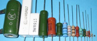
Let's consider more types of resistors according to their intended purpose. They are of general and special purpose. General purpose resistors have the following parameters:
- nominal from 1 Ohm to 10 MOhm,
- power from 0.125 W to 100 W,
- accuracy tolerance of at least 20%, 10%, 5%, 2% or 1%.
They are suitable for operation in networks with voltages of no more than 1000 V. They are used as current limiters or as loads for active circuit elements. Special-purpose resistors are superior to “regular” ones in one or more characteristics. These include:
- Manufactured with high precision (maximum permissible deviation of the nominal value is 1%), having high stability of parameters. They are called precision and ultra-precision.
- High frequency. They have a very small intrinsic capacitance, which is why they are used in high-frequency circuits.
- High voltage (for networks with voltages above 1000 V).
- High resistance. The rating is above 100 MOhm and the voltage is at least 400 V.
To repair household appliances, elements with normal characteristics are sufficient. In general, when replacing, you should adhere to the rule: install an element of the same denomination and with the same characteristics. If the element base is old and it is difficult to find exactly the same copy or it costs disproportionately, we look for an analogue. When selecting analogues, we choose the same denomination, but the characteristics may be a little better. You should not take anything worse, as this may cause the devices to malfunction.
Types and types of device
There are many types of trimming resistors on the market today. These are non-separable trimming resistors of type SP4-1, filled with epoxy compound, and intended for defense equipment, and trimmers of type SP3-16b for vertical mounting on a board.
It will be interesting➡ Diode bridge - what is it?
In the manufacture of household equipment, small trimming resistors are soldered onto the boards, which, by the way, can reach 0.5 watts in power. In some of them, for example in SP3-19a, metal ceramics are used as a resistive layer.
There are also very simple tuning resistors based on varnish film, such as SP3-38 with an open case, vulnerable to moisture and dust, and with a power of no more than 0.25 watts. Such resistors are adjusted with a dielectric screwdriver to avoid accidental short circuits. These simple resistors are often found in consumer electronics, such as monitor power supplies.
Some trimmer resistors have a sealed housing, for example R-16N2, they are adjusted with a special screwdriver, and are more reliable because dust does not get on the resistive track and moisture does not condense.
Powerful three-watt resistors of the SP5-50MA type in the case have holes for ventilation, in them the conductor is wound in the shape of a toroid, and the contact slider slides along it when the handle is turned with a screwdriver.
In some CRT TVs you can still find high-voltage trimming resistors, such as HP1-9A, with a resistance of 68 MOhm and a nominal power of 4 watts. Essentially, this is a set of cermet resistors in one package, and the typical operating voltage for this resistor is 8.5 kV, with a maximum of 15 kV. Today, similar resistors are built into TDKS.
In analog audio equipment you can find slider or slide variable resistors, such as SP3-23a, which are responsible for adjusting volume, timbre, balance, etc. These are linear resistors, which can also be double, such as SP3-23b.
What do linear resistors look like in a diagram?
Trimmer multi-turn resistors are often found in electronic equipment, measuring instruments, etc. Their mechanism allows you to precisely regulate the resistance, and the number of turns is measured in several tens.
The worm gear allows the sliding contact to turn slowly and move smoothly along the resistive track, allowing the circuits to be tuned very, very accurately.
It will be interesting➡ Chokes in electrics: what are they and where are they used?
For example, the SP5-2VB multi-turn tuning resistor is adjusted precisely by means of a worm gear inside the housing, and to completely pass the entire resistive track you need to make 40 turns with a screwdriver. Resistors of this type in various modifications have a power from 0.125 to 1 watt, and are designed for 100 - 200 adjustment cycles.
This is not a complete overview of the types and types of parts. As we can see from the previous description, tuning resistors are inherently close to variables, but strictly speaking, they are not. This video briefly but clearly describes how to convert a trimmer resistor into a variable resistor.
Classification according to operating conditions
According to the features of application and use, types of resistors are divided into groups.
Permanent
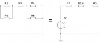
The resistance is constant with an acceptable normalized error and corresponds to the standard. On the electrical diagram they are depicted as a rectangle with sides 10x4 mm. Lead lines are drawn from the center of the narrow side. Next to the image they place the letter “R” with the serial number of the case according to the diagram. The denomination value is indicated here.
The scattering fits inside the rectangle. In imported technical documentation it is often depicted as a zigzag line connecting the terminals.
Variables and tuning
The components of a variable potentiometer are equipped with three or more terminals, and a mechanism for moving a slider - a current collector. The range of change extends from zero to a maximum limited by the set nominal value.
Changing the characteristics of the equipment during operation, such as adjusting the tuner, adjusting the volume level or lighting, is performed by a variable component.
The mechanism for moving the slider ends with a handle that allows for quick adjustments. If the setting is performed during commissioning and should not change daily, trimmers are used. The position of the current collector in them is set with a screwdriver.
Nonlinear
Automation and electronic protection devices actively use semiconductor nonlinear devices, the conductivity of which changes automatically with fluctuations in external environmental factors. The negative temperature coefficient of thermistors increases conductivity as the temperature increases and decreases as the temperature decreases.
A device with a positive TCS is called a posistor. In a photoresistor, the conductivity of the semiconductor layer increases with increasing illumination in the visible, infrared or ultraviolet spectrum.
Varistors are capable of increasing conductivity when the voltage applied to it increases
Magnetoresistors react to a magnetic field, and tensistors record the mechanical force applied to them.
Color marking on the resistor housing
When it appeared, I tried to remember the color marking and even memorize it - but nothing good came of it, I still got confused, and the resistor value had to be determined with a tester. Now I don’t remember when, but in one magazine I came across an article on how this whole thing can be avoided. There they talked about a cheat sheet made in the form of a resistor, only instead of colored stripes there are wheels on which the colors involved in designating the resistor values are written. Let's just look at the example shown in the photograph. Let's say we have a resistor with the following colors: green - blue - red. We need to determine its value:
With the first wheel you select the color of the first stripe (green), with the second wheel you select the color of the second stripe (blue), and with the third wheel you select the color of the third stripe (red) - this will be our multiplier. Now we multiply the resulting figure in the first two windows, and we got 56, by the factor obtained in the third window - that’s ten squared or 100. The result is 5600 Ohms or 5.6 kOhms. As you can see, the cheat sheet is very simple to use.
Color marking of domestic resistors
The end result will always be in Ohms, but it is not difficult to convert it to kiloohms or megaohms:
1000 Ohm is 1 kOhm; 10000 Ohm is 10 kOhm; 100000 Ohm is 100 kOhm; 1000 kOhm is 1 megaohm or 1,000,000 Ohms; 10 M is 10000 kOhm or 10000000 Ohm.
To make it, I used cardboard, but you can use any other material that is easy to process. If you use cardboard, then for strength it is advisable to glue it in two layers. I didn’t draw a drawing, but indicated all the dimensions directly on the cheat sheet, because it’s easier for me, and it’s clearer for you. Dimensions are indicated in millimeters.
The next step is to make three wheels. The first two will be the same, and they are marked with the colors of the stripes and the numbers corresponding to each color. The wheel must be divided into ten equal parts, and if you look at the right one, you can see that, for example, brown corresponds to one, and black corresponds to zero.
The sequence is:
- Black – 0;
- Brown – 1;
- Red – 2;
- Orange – 3;
- Yellow – 4;
- Green – 5;
- Blue – 6;
- Purple – 7;
- Gray – 8;
- White – 9.
Resistor with markings
Here the sequence is:
- Black – 1;
- Brown – 10;
- Red – 10 to the power of 2 (100);
- Orange – 10 to the power of 3 (1000);
- Yellow – 10 to the power of 4 (10000);
- Green – 10 to the power of 5 (100000);
- Blue – 10 to the power of 6 (1000000); Purple – 10 to the power of 7 (10000000);
- Gray – 10 to the power of 8 (100000000);
- White – 10 to the power of 9 (1000000000);
- Golden – 10 to the power of -1 (0.1);
- Silver – 10 to the power of -2 (0.01).
Secure the wheels with bolts with a diameter of 3 mm. In any case, if all else fails, the resistance of the resistor can always be measured with a multimeter. If you have any doubts about determining the band of the first number, refer to the tolerance band, which is located on the right side of the resistor. As a rule, the bulk of resistors come with a tolerance of five and ten percent, and these are golden and silver colors.
Resistor in the diagram
Resistor color coding
| Color | number | decimal factor | accuracy in % | TKS in ppm/°C | % failure |
| silver | — | «0,01» | ±10 | — | — |
| gold | — | «0,1» | ±5 | — | — |
| black | 0 | 1 | — | — | — |
| brown | 1 | «10» | ±1 | 100 | 1 % |
| red | 2 | «100» | ±2 | 50 | 0,1 % |
| orange | 3 | «1000» | — | 15 | 0,01 % |
| yellow | 4 | «10 000» | — | 25 | 0,001 % |
| green | 5 | «100 000» | ±0,5 | — | — |
| blue | 6 | «1 000 000» | ±0,25 | 10 | — |
| violet | 7 | «10 000 000» | ±0,1 | 5 | — |
| grey | 8 | «100 000 000» | — | — | — |
| white | 9 | «1 000 000 000» | — | 1 | — |
| absent | — | — | ±20 % | — | — |
For example, if a resistor is marked with four stripes: red, black, red and silver, then the first two stripes mean 20, the third 100, the fourth means accuracy - 10%. This means that the resistor resistance is 20·100 Ohm = 2 kOhm, accuracy ±10%.
To the main page To the beginning
The use of any materials from this page is permitted provided there is a link to the “Electrical is Easy” website.
How to test a resistor
Almost any multimeter is suitable for testing a resistor. With a fixed resistor, only two things can happen:
- The resistor breaks - its resistance tends to infinity;
- Strong change in resistance.
In the electrical circuit, it is easy to notice a burnt resistor - in this case, it should have been tested using a multimeter. It should be noted that a resistor break can occur without changing its appearance (without “burning”).
The resistor testing process is as follows:
- Determine resistance by digital or color markings;
- Set the multimeter to resistance measurement mode based on the resistor value;
- Check that the resistance matches that indicated on the housing.
If the resistor resistance is within acceptable limits (for carbon domestic resistors C1-4, permissible deviations from the nominal value can reach ±10%), then the resistor is in good condition. Otherwise, it needs to be replaced.
The process of testing fixed resistors using a digital multimeter is demonstrated in the video below.
Testing variable resistors is a little more complicated. It is necessary to check the quality of contact of the brush with the conductive element. In some cases, a faulty variable resistor can be repaired.
Features of trimming resistors
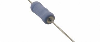
Resistor
Such radio components are necessary to configure equipment elements during repair, adjustment or assembly. The main difference between trimming resistors and other models is the existence of an additional locking element. The operation of these resistors uses a linear relationship.
Flat and ring resistive elements are used to create components. If we are talking about using devices under heavy loads, then cylindrical structures are used. In the diagram, instead of an arrow, a tuning adjustment sign is placed.
Resistor values.
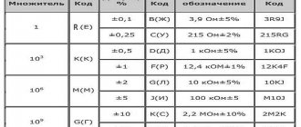
Resistor values are not arbitrary numbers. There are special series of ratings, which represent values from 0 to 10. So, resistor ratings (resistance values) can have values that are defined as the value from the corresponding series multiplied by 10 to the integer power. Let's look at the main rows - E3, E6, E12 and E24:
The number in the name of the series means the number of numbers in the series of denominations in the range from 0 to 10. In the E3 series there are three numbers - 1.0, 2.2, 4.7, similarly in other series. Thus, if the resistor is from the E3 series, then its nominal value (resistance) can be 1 Ohm, 2.2 Ohm, 4.7 Ohm, 10 Ohm, 22 Ohm, 47 Ohm... 1 KOhm... 22 KOhm, etc. There are also nominal series E48, E96, E192 - their difference from the series we considered is only that there are even more permissible values
Notation system
All of the above features of the parameters are usually reflected in the full name of the potentiometer in the technical or product-production documentation.
Below is the designation system for variable resistors according to the current specifications.
Rice. 2.2. Designation system for variable resistors of domestic companies.
First element (letters and numbers)
denotes the resistor type and design option.
Second element (letter)
denotes the permissible power dissipation in watts.
Third element (numbers and letters)
denotes the nominal resistance.
Fourth element (numbers)
denotes the permissible deviation of resistance from the nominal value (in%).
Fifth element (letter)
denotes the dependence of the resistance of a variable resistor on the position of the moving contact.
Sixth element (numbers and letters)
denotes the type of protruding part of the shaft.
Seventh element (numbers)
indicates the size of the protruding part of the shaft.
Eighth element (letter)
denotes a delivery document.
Below we will consider the designation system for foreign resistors using the example of Bourns (Fig. 2.3).
First element (letters and numbers)
denotes a series (model) of a variable resistor.
Second element (digit)
denotes the number of sections (groups) of variable resistors (if there is only one section, then this element is missing).
Third element (number or letter)
indicates the location of the pins and their shape (Table 2.1.).
Fourth element (letter)
indicates the presence (“S”) or absence (“N”) of an additional switch (may be absent in the designation of some series of resistors).
Fifth element (numbers)
indicates the shaft length in mm.
Sixth element (numbers)
denotes the rated resistance code
Rice. 2.3. Bourns designation system for variable resistors.
Location of resistor terminals relative to the housing
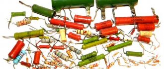
A resistor (Latin resisto - resist) is one of the most common radio elements, and the variable resistor in a simple transistor receiver amounts to several tens, and in a modern TV - up to several hundred.
A variable resistor is a resistor in which the electrical resistance between the moving contact and the terminals of the resistive element can be changed mechanically.
Resistors act as load and current-limiting elements, voltage dividers, additional resistances and shunts in measuring circuits, etc. The main task of a resistor is to provide resistance, that is, to block the flow of electric current. Resistance is measured in ohms, kilo-ohms (1000 ohms) and mega-ohms (1,000,000 ohms).
Correspondence of markings of tuning resistors Murata and Bourns
| Marking Murata | Bourns marking |
| PVZ3A201A01R00 | TC33X-1-201E |
| PVZ3A501A01R00 | TC33X-1-501E |
| PVZ3A102A01R00 | TC33X-1-102E |
| PVZ3A152A01R00 | TC33X-1-202E |
| PVZ3A502A01R00 | TC33X-1-502E |
| PVZ3A103A01R00 | TC33X-1-103E |
| PVZ3A153A01R00 | TC33X-1-203E |
| PVZ3A203A01R00 | TC33X-1-203E |
| PVZ3A503A01R00 | TC33X-1-503E |
| PVZ3A104A01R00 | TC33X-1-104E |
| PVZ3A105A01R00 | TC33X-1-104E |
Color coding of resistors.
Most resistors are color coded, like the one in this picture. It consists of 4 or 5 stripes (most often, although there can be, for example, 6) of certain colors, and each of these stripes carries a certain meaning. The first two stripes absolutely always indicate the first two digits of the nominal resistance of the resistor. If there are 3 or 4 stripes in total, then the third stripe will indicate the multiplier by which you need to multiply the number obtained from the first two stripes. When there are 4 bands on a resistor, the fourth will indicate the accuracy of the resistor. And in the case when there are only five bands, the situation changes somewhat - the first three bands mean three digits of the resistor resistance, the fourth is the multiplier, the fifth is the accuracy. The correspondence of numbers to colors is given in the table:
There is another important point here - which lane should be considered first? Most often, the first strip is considered to be the one that is located closer to the edge of the resistor. In addition, you can notice that the gold and silver stripes cannot be first, since they do not carry information about the value of resistance. Therefore, if the resistor has stripes of this color and they are located on the edge, then we can say for sure that the first stripe is on the opposite side. Let's look at a practical example:
Since we have 5 bands here, the first three indicate the resistance of the resistor. Having looked at the required values in the table, we get the value 510. The fourth band is the multiplier - in this case it is equal to 103. And, finally, the fifth band is the error - 10%. As a result, we get a resistor of 510 KOhm, 10%.
In principle, if you don’t want to deal with colors and values, then you can turn to some automated service that determines resistance by color markings. There you will only need to select the colors that are applied to the resistor and the service itself will display the resistance value and accuracy.
So, we’ve sorted out the color coding of resistors, let’s move on to the next question...
Variable resistors.
Structurally, variable resistors consist of a conductive surface with two ohmic contacts, essentially an open planar constant resistor, wire or carbon, and a contact sliding along it - a current collector.
The value of the electrical resistance of a variable resistor can be smoothly changed from zero to the nominal value. This is achieved by moving a sliding contact along a conductive surface.
The figure below shows a variable resistor without a back cover and its circuit designation.
The purpose of trimming resistors is to fine-tune the operating modes of electronic devices. Moreover, the setting position, as a rule, does not change throughout the entire further life of the device. Therefore, the sliding contact movement drive device is adapted to be adjusted using a screwdriver, and no special requirements are placed on the strength of the conductive layer.
Adjustment resistors are intended for regular use - for example, to change the volume level of sound-conducting devices. Their mechanical properties must meet special requirements - the conductive layer along which the current collector slides must be particularly resistant to mechanical stress. The drive for moving the sliding contact is equipped with an extended handle for greater ease of use.
Potentiometers
The potentiometer differs from other types of resistance in that it has three terminals:
- 2 permanent, or extreme;
- 1 movable, or middle.
The first two terminals are located at the edges of the resistive element and are connected to its ends. The middle output is combined with a movable slider, through which movement occurs along the resistive part. Due to this movement, the resistance value at the ends of the resistive element changes.
All variants of variable resistors are divided into wire and non-wire, this depends on the design of the element.
How does a resistor work?
To create a non-wire variable resistor, rectangular or horseshoe-shaped plates from insulate are used, on the surface of which a special layer is applied that has a given resistance. Typically the layer is a carbon film. Less commonly used in design:
- microcomposite layers of metals, their oxides and dielectrics;
- heterogeneous systems of several elements, including 1 conductive element;
- semiconductor materials.
Attention! When using resistors with carbon film in the power circuit, it is important to prevent the element from overheating, otherwise sudden voltage drops may occur during the adjustment process.
When using a horseshoe-shaped element, the slider moves in a circle with a rotation angle of up to 2700C. Such potentiometers have a round shape. The rectangular resistive element has a translational slider movement, and the potentiometer is made in the form of a prism.
Wire options are built on the basis of high-resistance wire. This wire is wound around a ring-shaped contact. During operation, the contact moves along this ring. In order to ensure a strong connection to the contact, the track is additionally polished.
What does a wire-wound variable resistor look like?
The material used depends on the accuracy of the potentiometer. Of particular importance is the diameter of the wire, which is selected based on the current density. The wire must have high resistivity. In production, nichrome, manganin, constatin and special alloys of noble metals, which have low oxidation and increased wear resistance, are used for winding.
In high-precision instruments, ready-made rings are used where the winding is placed. For such winding, special high-precision equipment is required. The frame is made of ceramics, metal or plastic.
If the accuracy of the device is 10-15 percent, then a plate is used, it is rolled into a ring after winding. Aluminum, brass or insulating materials, for example, fiberglass, textolin, getinax, are used as a frame.
Note! The first sign of resistor failure may be a crackling or noise when turning the knob to adjust the volume. This defect occurs as a result of wear of the resistive layer, and, therefore, loose contact.
Parameters and characteristics
There are a number of parameters that characterize the component in operation and they are necessarily taken into account by developers when selecting a radio component. Technical characteristics of resistors are available in reference literature. Let's dwell on the parameters that are written on the case or can be determined by appearance.
Denomination
The table shows the series whose number values are most often used in practice. The required denomination is formed from a table element with a decimal coefficient of the corresponding degree.
Tolerance
The largest difference between the actual value and the nominal value, expressed as a percentage, is called the tolerance or accuracy class. The manufacturer is obliged to provide the necessary tolerance according to the selected range of preferred values and bring the product to the required accuracy class.
For the E6 series, a value deviation of ±20% is allowed, for E12 ±10%, and E24 allows a manufacturing inaccuracy not exceeding ±5%. Normal operation of most circuits is ensured by radio components of class 5-10%. If it is necessary to use increased accuracy, this is indicated on the electrical diagram.
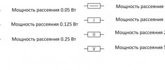
Power dissipation
For each model, the amount of heat dissipation is normalized. If during operation the heat generated exceeds the dissipation, the housing will heat up and subsequently fail. Developers carefully calculate the heat dissipation power of the radioelements used and indicate the values in the technical documentation.
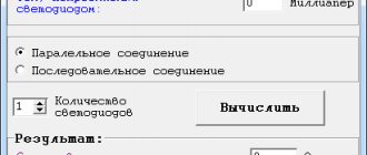
For a homemade device, it is easy to calculate the required resistance value and dissipation.
For example: The LED is connected to a source with voltage U=9 V (volts). It is known that the operating voltage of the LED is Usv = 3.7 V, the operating current Isv = 5 mA (= 0.005 ampere). The LED and the resistor are connected in series, the current is the same.
We calculate the voltage that needs to be extinguished: Uр = Ui-Usv = 8-3.7 = 4.3 V.
Required: Rг=Uр/Iсв=4.3/0.005=870, the nearest one in the E24 row is equal to 910 Ohm.
We determine P=Uр*Isv=4.3*0.005=0.02 W (Watt)
Rule: The power of the installed element is selected to be one and a half to two times the calculated value. Suitable 910 ohms with 0.05 watt dissipation.
Application area
Trimmer variable resistors are widely used in electronic and electrical devices. They are used to adjust the current value in circuits and as voltage dividers. At low frequencies up to 1 megahertz, no problems are observed with their use.
When operating at high frequencies, the resistors’ own inductance and capacitance begin to affect; this factor must be taken into account. When selecting parts, you should pay attention to the operating frequency range. It is not recommended to work with the maximum permissible resistor parameters.
Cleaning the trimmer with regular alcohol
The resistor in circuits can become dirty; its slider track becomes covered with a layer of dust over time. And in order to return the electrical resistance to its previous performance, you just need to clean it.
Cleaning trimmer resistors is quite simple and quick. It is best to use pure alcohol for these purposes. It is better not to use various products such as nail polish remover, moonshine, or cleaners, as they may contain impurities that negatively affect the cleanliness of the resistor.
So, we disassemble the resistor (if it has a protective casing), for this it is usually enough to unbend the small metal clips on the resistor body itself, after which you need to remove this cover. Inside the resistor we will see a track along which the slider of the middle terminal of the resistor moves. It is this path that needs to be cleaned from dirt with alcohol.
It’s convenient to do this: take a syringe (let’s say 2 cc), fill it with alcohol, and carefully apply a few drops through the needle of the syringe directly onto the resistor track. After this, we begin to rotate this resistance in different directions so that the alcohol spreads throughout the entire track and thereby clears the way for the slider.
How to clean a resistor at home.
In principle, this is enough so that after assembling and installing the tuning resistor in our circuit workplace, we can enjoy its normal operation without previous problems. Although, if space on the resistor itself allows, you can also carefully go over it with a cotton swab, which will completely remove all dirt from the slider track.
Well, then we need to put our updated resistor back together and put it in our workplace. In most cases, after such cleaning, the electrical resistance is completely restored, and the intermittency of its operation disappears.
Difficult cleaning cases
In very rare cases, it is not a matter of dirt, but, for example, the destruction of this path as a result of excessive overheating. This can happen when too much voltage is accidentally applied to this resistor and the power of this resistor is not large enough to quickly dissipate the generated heat from the high current. This is where the variable resistor track heats up greatly, followed by its destruction. Cleaning with alcohol won't help here.
This resistor needs to be completely replaced with a new one that is known to work. And, of course, before installing a new resistor on the old circuit, check it so that the process of destroying the track does not repeat with a new resistance.
Unfortunately, not all types of variable and trimming resistors can be cleaned using the above method. Sometimes there is resistance in the solid body, which makes it impossible to reach the slider track.
Here you can go to extreme measures. Make a small hole in the body (with a 0.8-1 mm drill). Well, pour alcohol through it with a syringe through a needle. Next, again turn the resistor knob in different directions and then you need to wait until the alcohol has completely evaporated.
You can warm up this variable resistor a little (up to 50 degrees), this will speed up the evaporation of alcohol. Although pure alcohol is a dielectric, it does not conduct current through itself. Consequently, it will not negatively affect the operation of the variable resistor, even if there is some alcohol left on it, which will still evaporate.
Connection schemes
The trimmer resistor circuit exists in two main versions. The first option is a rheostatic switching circuit, used as a current regulator. With this connection method, the initial or final terminal of the resistor and the middle one are used. Sometimes the middle terminal is connected to one of the extreme ones. This circuit is more reliable, since if the middle pin loses contact, the electrical circuit does not break.
The second connection option is a potentiometric circuit, where a resistor is used as a voltage divider. With this connection, all pins are used.
Of great importance is how the resistance of the trimmer changes depending on the angle of rotation of the control knob. This dependence is called a functional characteristic; there are three types.
The main characteristic is linear. As you can see, the resistance is proportional to the change in the angle of rotation of the handle. The other two are logarithmic and antilogarithmic, used mainly in amplifiers.
Basic parameters of variable resistors
The parameters of variable resistors can be divided into two groups: parameters common to fixed resistors and special parameters characteristic only of variable resistors.
Parameters common to fixed resistors:
- ;
- ;
- ;
- ;
- ;
Special parameters for variable resistors:
- Functional characteristics
- Resolution
- Minimum resistance
- Wear resistance
Functional characteristics
Functional characteristic (taper) – dependence of the resistance of a variable resistor on the position of the moving contact. The functional characteristics of a variable resistor are:
- linear;
- nonlinear.
Variable resistors with a nonlinear characteristic are usually used in audio equipment to adjust the volume level, timbre, etc. The most widely used nonlinear characteristics are:
- logarithmic;
- inverse logarithmic.
A - linear (linear), B-logarithmic (Reverse Log, Reverse Audio), B-reverse logarithmic (Logarithmic, Audio) It is worth noting that the designation of functional characteristics in domestic documentation differs from foreign ones: the reverse logarithmic characteristic in foreign documentation is designated as Logarithmic.
Resolution
Resolution is the minimum change in resistance with minimal movement of the control knob. This parameter is applicable only to wirewound potentiometers and is determined by the resistance between adjacent turns. Non-wire potentiometers have very high resolution and are determined by defects in the resistive layer.
Wear resistance
Wear resistance is the ability of a potentiometer to maintain its parameters during operation. As a rule, it is expressed by the number of cycles of movement of the contact assembly during which the characteristics of the potentiometer remain within the specified limits.
Graphic designation
According to the standard, there are several options for the conventional graphic designation (CGO) of various variable resistors.
The figure shows UGOs used in Europe and Russia. The first two are a general designation, the third is a resistance with a linear characteristic depending on the angle of rotation of the control knob, the fourth is a resistance with a nonlinear dependence. The first and second types of resistors are used for switching on according to a potentiometer circuit, and the third and fourth types are used according to a regulator circuit.
The tuning resistor, the designation of which is given below, is depicted in two ways according to the standard.
The first sign denotes resistors that act as current regulators. The second method is intended for resistors connected according to a potentiometer circuit.
In the USA, Japan and some other countries, other UGOs are used.
There are no fundamental differences, but it is good to know both designations.
Marking
Alphanumeric code
Elements with wire leads are identified by writing on the surface of the housing. The numbers indicate the denomination, and the letters indicate the measurement range. The letters "E" and "R" are for ohms, "K" is for kilohms, and "M" is for megohms.
The letter in the marking acts as a decimal point. For example, the designation 5R8 corresponds to a resistance of 5.8 Ohms, 7K8 means 7.8 kOhms, and M59 equals 590 kOhms.
Color coding
For small components whose labels cannot be read, color marking of resistors using colored stripes has been developed.
A number of colored stripes are shifted to the edge of the case, and the countdown begins from the stripe closest to the edge.
If the marking contains five bars, then the first three will show the resistance value in ohms, the next one determines the multiplier, and the last one indicates the tolerance.
Coding of SMD elements
The photo of surface-mount resistors shows that small sizes require the use of other designation methods. Manufacturers have introduced three basic methods of coding, combining products into groups by size.
Products with a tolerance of 2, 5 and 10%. There is a digital mark on the case, for example 330, 683, 474. The first two numbers indicate the mantissa, and the third acts as an indicator of the power of the number 10. Accordingly, the inscription 330 shows 33*1=33 Ohm, 683 means 68*1000=68 kOhm, 473 respectively 47* 10000=470 kOhm. Some models use the letter "R" as a decimal point.
Models of size 0805 and others with a one-percent tolerance are designated according to a principle similar to the first group: the first three digits are the mantissa, the fourth, the multiplier is a power of the base 10, it is also allowed to use the letter “R”. Set 7430 corresponds to a value of 743 ohms
SMD size 0603 are marked with a combination of two numbers and a letter, which determines the degree of the multiplier: A - zero degree, B - first, C - second, D - third, E - fourth, F - fifth, R - minus the first, S - minus the second , Z – minus the third power. The number indicates the code by which the mantissa is found in the EIA-96 table.
For example, code 75C. 75 in the table corresponds to 590. The letter “C” indicates a multiplier of 100. Accordingly, 590*100=59 kOhm.
Error
Marking with four or five stripes for output resistors has become traditional. It indicates accuracy. The more stripes, the higher this indicator. SMD resistors for surface mounting on a board with tolerances of 2, 5 and 10 percent are designated by numbers. The first order of digits must be multiplied by ten to the third power.
The letter "R" indicates the decimal point. For example, the R473 marking indicates that 0.47 must be multiplied by ten to the third power for a total of 470 ohms. The remaining two numbers and a letter are used to designate standard sizes. The letter indicates the exponent of ten.
Resistors are one of the important components of a printed circuit board. They not only reduce voltage and current, but also dissipate heat. Each component has colored stripes that correspond to their ratings.