In 1827, Georg Ohm published his research, which forms the basis of the formula used to this day. Ohm performed a large series of experiments that showed the relationship between the applied voltage and the current flowing through a conductor.
Arduino kit
Keyestudio Super Starter Kit with V4.0 board for Arduino…
More details
This law is empirical, that is, based on experience. The designation "Ohm" is adopted as the official SI unit for electrical resistance.
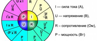
Ohm's law for a section of a circuit states that the electric current in a conductor is directly proportional to the potential difference in it and inversely proportional to its resistance. Taking into account that the conductor resistance (not to be confused with resistivity) is a constant value, this can be expressed using the following formula:
Where
- I - current in amperes (A)
- V - voltage in volts (V)
- R - resistance in ohms (Ohm)
For clarity: a resistor with a resistance of 1 Ohm, through which a current of 1 A flows, has a potential difference (voltage) of 1 V at its terminals.
The German physicist Kirchhoff (famous for his Kirchhoff rules) made a generalization that is more used in physics:
Infrared heater with thermostat + lamp
Quick heating of the room, individual temperature in each room…
More details
Where
- σ – material conductivity
- J - current density
- E is the electric field.
Current flowing in a circuit of parallel connected resistors
When considering the corresponding sections of branched circuits, it is necessary to remember that the currents at the input and output of each node are equal, as well as before and after the group of parallel resistors. This rule will help check the correctness of the calculations. If the marked correspondence is not met, the calculation error is eliminated.
Using the initial data discussed above for two complex circuits, a calculation can be made for each individual branch.
Example 1:
- the total current in the circuit is 0.8 A;
- the distribution of voltages in individual sections is easy to determine from the calculated equivalent resistances: U12 = I * Req1 = 0.8 * (2*4)/ (2 4) = 0.8 * 1.3 = 1.04 V;
- The current values are calculated using the standard algorithm: I1 = U12/R1 = 0.52 A, I2 = U12/R2 = 0.26 A;
- summation checks the correctness of the calculations: I = I1 I2 = 0.52 0.26 ≈ 0.8 A.
Example 2 (mixed method of connecting resistors):
- current in this version is 1.2 A;
- the voltage in the section with a group of parallel resistors is Uab = I * Reeq(12345) = 1.2*2.5 = 3V;
- By analogy with the previous example, it is easy to calculate the current in each individual branch: I12 = Uav/(R1 R2) = 3/ (15 5) = 0.15 A;
- I3 = Uav/ R3 = 3/ 5 = 0.6 A;
- I4 = Uav/ R4 = 3/ 10 = 0.3 A;
- I5 = Uav/ R5 = 3/20 = 0.15 A;
- According to the rule of equality of currents at the input and output of the node, the correctness of the calculations made is checked: I = I12 I3 I4 I5 = 0.15 0.6 0.3 0.15 = 1.2 A.
READ MORE: Is it possible to install a voltage regulator on a compressor?
P = I2 *R = U2/ R.
For your information. The design of each element is designed for a specific operating temperature range. Exceeding the threshold can destroy the part, the soldering point, and neighboring components. One should not forget about a simultaneous significant change in resistance, which can disrupt the functional state of the electrical circuit.
For the calculation, select a suitable formula taking into account the known initial parameters (data from example 2 in the previous section):
- current – 1.2 A;
- at resistance R6=7.5 Ohm the power dissipation will be: P6 = I2 *R = 1.44 * 7.5 = 10.8 W;
- It is difficult to find such a resistor, since the standard range offers ratings from 0.05 to 5 W;
- in another circuit (R5=20 Ohm) the calculated current will be 0.15 A, so P5= 0.0225 * 20 = 0.45 W;
- in this case, you can choose a product with a suitable dissipation power in the standard range of 0.5 W (experts recommend making a 1.52-fold margin, so it is better to use a 1 W resistor).
Standard symbols on electrical diagrams and typical power ratings
For your information. When choosing resistors, you should take into account the product class in terms of electrical resistance accuracy. In serial parts, deviations of 5-20% are acceptable.
Select the appropriate option (combination) taking into account the available initial data. It should be remembered that there is a single voltage at the input and output and different currents in individual branches. Computing technology is discussed in previous sections.
The total current I flowing in a circuit of parallel resistors is equal to the sum of the individual currents flowing in all parallel branches, and the current in a single branch does not necessarily have to be equal to the current in adjacent branches.
Despite the parallel connection, the same voltage is applied to each resistor. And since the value of resistance in a parallel circuit can be different, the amount of current flowing through each resistor will also be different (as defined by Ohm’s law).
Let's consider this using the example of two resistors connected in parallel. The current that flows through each of the resistors (I1 and I2) will be different from each other since the resistances of resistors R1 and R2 are not equal. However, we know that the current that enters the circuit at point "A" must leave the circuit at point " B"
I = I1 I2
Current flowing in R1 = U ÷ R1 = 12 ÷ 22 kOhm = 0.545 mA
Current flowing in R 2 = U ÷ R2 = 12 ÷ 47 kOhm = 0.255 mA
I = 0.545 mA 0.255 mA = 0.8 mA
I = U ÷ R = 12 V ÷ 15 kOhm = 0.8 mA (same)
where 15 kOhm is the total resistance of two parallel connected resistors (22 kOhm and 47 kOhm)
And in conclusion, I would like to note that most modern resistors are marked with colored stripes and their purpose can be found out here.
How to calculate complex resistor wiring diagrams
If you combine a larger number of elements, you need to add the required number of terms to the formulas considered.
READ MORE: Accident at the Sayano-Shushenskaya HPP: causes and consequences || Is it true that you can’t point your finger up at the Sayano-Shushenskaya HPP?
Initial data:
- DC source 12V;
- resistance of parallel resistors, Ohm: 10, 40, 60, 80.
Calculation:
- basic formula: 1/Req = 1/R1 1/R2 1/R3 1/R4;
- Substituting the initial data, calculate the conductivity: G = 1/Req = 1/10 1/40 1/60 1/80 = 0.1 0.025 0.0166 0.0125 = 0.1541;
- equivalent resistance: Req = 1/0.1541 ≈ 6.5 Ohm;
- current in the circuit: Itot = Uip/ Req = 12/ 6.5 ≈ 1.85 A.
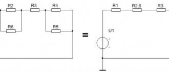
Complex circuits
Using a similar technology, calculations are made for more complex circuits. The figure shows the resistance values. In both cases, the same power source is used with Uip = 12V.
Calculation 1 (serial and parallel connection):
- for each parallel section you can use the formula: Rtot = 1/ (1/R1 1/R2) = R1*R2/R1 R2;
- equivalent resistance of the first part: Req1 = (2*4)/ (2 4) = 1.3 Ohm;
- second: Req2 = (15*5)/ (15 5) = 3.75 Ohm;
- general: Req = 1.3 10 3.75 = 15.05 Ohm;
- Itot = Uip/ Req = 12/ 15.05 ≈ 0.8 A.
Calculation 2 (complex parallel connection):
- in this option, first calculate the conductivity of the part (R3, R4, R5) using the formula: G345 = 1/5 1/10 1/ 20 = 7/20 = 0.35 sim;
- Req (345) = 1/0.35 ≈ 2.857 Ohm;
- total value for the circuit: R1 R2 = 20 Ohm;
- By analogy with the previous method, they determine: G12345 = 0.4 sim and Req(12345) = (20*2.857)/ 20 2.857) ≈ 2.5 Ohm;
- after adding the last element (R6 = 7.5 Ohm), the final result is obtained: Req = 2.5 7.5 = 10 Ohm;
- division determines the current strength in the load connected to a 12 V current source: I = 12/10 = 1.2 A.
The last example uses an additional circuit component (R6). Accordingly, for this circuit the above-discussed proportion of equal voltages (source and connected load) will not be satisfied.
U6 = I *R6 = 1.2 * 7.5 = 9 V.
Uab = I * Reeq(12345) = 1.2*2.5 = 12-9 =3V.
The second part of the formula demonstrates the test by subtracting voltages (Uip - U6).
For ease of calculation, we first group the resistors by parallel and series connection types. Resistors R2 and R3 are connected in series (group 2). They, in turn, are connected in parallel with resistor R1 (group 1).
Calculation of more complex connections of resistors can be performed using Kirchhoff's laws.