Voltage, Current and Resistance
An electrical circuit is formed when a conductive path is created that allows electrical charge to travel continuously. This continuous movement of electric charge through the conductors of a circuit is called current, and is often spoken of as a “flow,” like the flow of liquid through a hollow pipe.
The force that causes charge carriers to “flow” through a circuit is called voltage. Voltage is a special measure of potential energy that is always relative between two points. When we talk about a certain amount of voltage present in a circuit, we are talking about the measurement of the potential energy to move charge carriers from one specific point in that circuit to another specific point. Without mentioning two specific points, the term "tension" has no meaning.
Current generally passes through conductors with some degree of friction or resistance to movement. This opposition to movement is more correctly called resistance. The amount of current in the circuit depends on the amount of voltage and the amount of resistance in the circuit that prevents the passage of current. Like voltage, resistance is a quantity measured between two points. For this reason, voltage and resistance values are often specified as "between" two points in a circuit.
Voltage from a hydraulic point of view
You have all seen and can imagine what a water tower or just a water tower looks like. Roughly speaking, this is a large, tall “glass” filled with water.
water tower
So, let’s imagine that the tower is filled to the top with water. It turns out that at the moment there is wow pressure at the bottom of the tower!
water tower filled with water
What if you drained at least half the water from the tower? The pressure at the bottom of the tower will be halved. Let's pour one bucket of water into the empty tower! The pressure on the bottom of the tower will be negligible.
Imagine this situation. We have a water carrier, and we plugged the hose with a stopper.
The water seems ready to run, but there is nowhere to run! The plug tightly clogs the hose. But the plug itself is now under pressure created by the pumping station. What does the pressure on the plug depend on? I think it’s clear that it depends on the power of the pump. If the pump power is high, the plug will fly out at the speed of a bullet, or the pressure will rupture the hose if the plug sits tightly in the hose. In this case, pressure is created using a pump. That is, we can say that this is a model of a water tower in a horizontal position.
The same can be said about the water tower. Here the pressure on the bottom is created by gravitational force. As I already said, the pressure at the bottom of the tower depends on how much water is in the tower at the moment. If the tower is filled to capacity with water, then the pressure at the bottom of the tower will be high, and vice versa.
Now imagine the pressure at the bottom of the ocean, especially in the Mariana Trench! What can be said about pressure in these two cases? It seems to be there, but the water molecules stand still and don’t move anywhere . Remember this moment. There is pressure, but there is no movement.
Units of measurement: volts, amperes and ohms
To be able to make meaningful statements about these quantities in circuits, we need to be able to describe their quantities in the same way that we might quantify mass, temperature, volume, length, or any other physical quantity.
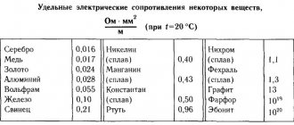
For mass we can use the units "kilogram" or "gram". For temperature, we can use Fahrenheit or Celsius. The table below shows the standard units of measurement for electrical current, voltage and resistance: Units of measurement for current, voltage, resistance
| Magnitude | Symbol | Unit | Unit abbreviation |
| Current | I | Ampere | A |
| Voltage | V | Volt | IN |
| Resistance | R | Ohm | Ohm |
The "symbol" assigned to each quantity is the standard letter of the Latin alphabet used to represent that quantity in formulas. Such standardized letters are common in all physical and engineering disciplines and are recognized throughout the world. The "unit abbreviation" for each quantity is the alphabetical character(s) used as an abbreviation for a specific unit of measurement.
Each unit of measurement is named after a famous electrical experimenter: the ampere after the Frenchman Andre M. Ampere, the volt after the Italian Alessandro Volta, and the ohm after the German Georg Simon Ohm.
The mathematical symbol for each quantity also has a meaning. "R" for resistance and "V" for voltage are self-explanatory ("Resistance" and "Voltage", respectively), while "I" for current seems a little strange. The letter "I" is supposed to represent "Intensity" (charge flow). Based on the research I've been able to do, there seems to be some disagreement about the meaning of the "I" word. Another voltage symbol, "E", stands for "Electromotive force". The symbols "E" and "V" are for the most part interchangeable, although in some texts "E" is reserved for voltage at a source (such as a battery or generator) and "V" for voltage at any other element.
All of these symbols are expressed in capital letters, except when a quantity (especially voltage or current) is described in terms of a short period of time (called "instantaneous" values). For example, a battery voltage that is stable over a long period of time will be symbolized by a capital letter "E", whereas the peak voltage when a lightning strike occurs just as it hits the power line will most likely be symbolized by a lowercase letter "e". (or a lowercase "v") to mark the value as existing at one point in time. The same lowercase convention holds true for current: a lowercase "i" represents current at some point in time. However, most measurements in DC circuits that are stable over time will be indicated by capital letters.
Electrical voltage
This pressure on the bottom is the same tension (by analogy with hydraulics). In this case, the bottom of the tower is zero, the initial reference level. The initial reference level in electronics is taken to be the terminal of a battery or accumulator with a minus sign. You could even say that the water level in the tower of a 12V car battery is higher than the water level of a 1.5V AA battery.
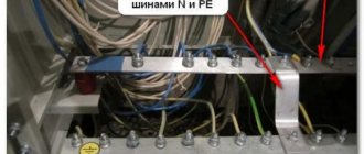
So, by analogy with electronics, this pressure is called voltage . For example, you have probably heard such an expression more than once, like “the power supply can produce from 0 to 30 Volts.” Or, in childish language, create “electrical pressure” at your terminals (marked in the photo) from 0 to 30 Volts. The zero level, where the electrical pressure is measured, is indicated by a minus.
DC power supply
Electrical voltage does not mean that electric current flows in an electrical circuit. In order for an electric current to appear, electrons must move in one direction, but at the moment they are stupidly standing still. And since there is no movement of electrons, then there is no electric current.
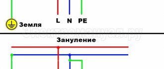
From an electronics point of view, there is pressure on one probe of the power supply, but not on the other. That is, this is the ground on which the tower stands, if we draw an analogy with hydraulics. Therefore, they try to make the positive probe of the power supply and indeed all devices red, like, beware, there is high pressure here! And the negative probe is black or blue.
In electronics, to indicate which terminal has more “electrical pressure” and which has less, two signs are put down: plus and minus , respectively positive and negative . On the positive side there is excess “pressure”, and on the negative side there is zero pressure.
Therefore, if you close these two terminals together, the electric current will flow from plus to minus, but it is highly not recommended to do this directly, since this will already be called a short circuit.
Coulomb and electric charge
One of the basic units of electrical measurement that is often taught early in electronics courses but not often used subsequently is the coulomb, a unit of electrical charge proportional to the number of electrons in an unbalanced state. One coulomb of charge corresponds to 6,250,000,000,000,000,000 electrons. The symbol for the amount of electric charge is the capital letter "Q", and the unit of coulombs is denoted "C". The unit of current, ampere, is equal to 1 coulomb of charge passing through a given point in a circuit in 1 second. In this sense, current is the speed at which an electric charge moves through a conductor.
As stated earlier, voltage is a measure of the potential energy per unit of charge available to stimulate the flow of current from one point to another. Before we can define exactly what a "volt" is, we must understand how to measure this quantity, which we call "potential energy." The common metric unit for measuring energy of any kind is the joule, which is equal to the amount of work done by a force of 1 newton when moving 1 meter (in the same direction). In these scientific terms, 1 volt is equal to 1 joule of electrical potential energy per (divided by) 1 coulomb of charge. Thus, a 9-volt battery releases 9 joules of energy for every coulomb of charge passing through the circuit.
These units and symbols for electrical quantities will become very important when we begin to explore the relationships between them in circuits.
Explanation in simple words
Electrical voltage U is the very reason that “forces” electric current I to flow. Electrical voltage always occurs when the charges are separated from each other, that is, all the negative charges are on one side, and all the positive charges are on the other. If you connect these two sides with an electrically conductive material, an electric current will flow.
The generally accepted definition of the term "electrical voltage".
Electrical voltage (or simply voltage) is the potential difference between two points in an electric field. It is the driving force for electric charge.
Potential in an electric field is the energy of a charged body, independent of its electric charge. For clarification, you can look at the comparison with the water circuit just below in the article.
There is another definition (from an 8th grade physics textbook):
Voltage is a physical quantity that characterizes an electric field. The electric voltage between two points of the electric field is numerically equal to the work done when a charge of 1 C is transferred between them by the forces of the electric field.
Comparison using a water flow model.
A good analogy to help you think about electrical voltage and potential is a water circuit. In this design, you have two pools at different heights that are connected by a pipe. In this pipe, water can flow from the upper pool to the lower one. The water is then pumped back to the upper basin using a pump as shown in the picture below.
Electrical Voltage - Comparison Using Water Flow Model
In your thinking, you can now easily compare a pump with a source of electrical voltage. In addition, the flow of water can be compared to electric current. The pump transports water from the lower pool to the upper one. From there it flows independently back to the lower pool. In this example, the pump is the flow driver. The greater the difference in height, the stronger the flow. The decisive factor is the potential energy of the upper basin. You can compare the difference in energy between the two pools with the difference in electrical potential. Simply put, a greater difference in height equals a greater electrical voltage.
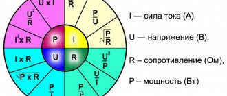
Ohm's law formula
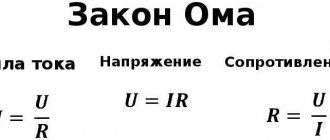
Ohm's main discovery was that the amount of electric current flowing through a metal conductor in a circuit, at any given temperature, is directly proportional to the voltage applied to it. Ohm expressed his discovery in the form of a simple equation describing the relationship between voltage, current and resistance:
\[E=IR\]
In this algebraic expression, voltage (E) equals current (I) times resistance (R). Using algebra, we can transform this equation into two other variants, solving it for I and R respectively:
\
\
Current work
Let us immediately introduce a new definition.
Current work is the work done by the forces of the electric field that create the electric current.
In the process of this work, the energy of the electric current is converted into other various types of energy (mechanical, internal, etc.). We talked about this in more detail when we looked at the effects of current.
Analyzing simple circuits using Ohm's law
Let's see how these formulas work to help us analyze simple circuits:
Figure 1 – Example of a simple circuit
In the above circuit, there is only one voltage source (the battery on the left) and only one current resistance source (the lamp on the right). This makes it very easy to apply Ohm's law. If we know the values of any two of the three quantities (voltage, current, and resistance) in this circuit, we can use Ohm's law to determine the third.
In this first example, we will calculate the amount of current (I) in the circuit, given the voltage (E) and resistance (R) values:
Figure 2 - Example 1. Source voltage and lamp resistance are known
What is the current (I) in this circuit?
\
In the second example, we will calculate the value of resistance (R) in the circuit, given the values of voltage (E) and current (I):
Figure 3 – Example 2. Source voltage and current in the circuit are known
What resistance (R) does the lamp provide?
\
In the last example, we will calculate the amount of voltage supplied by the battery, taking into account the current (I) and resistance (R) values:
Figure 4 - Example 3. The current in the circuit and the lamp resistance are known
What voltage does the battery provide?
\
Varieties
There are two types: constant and variable. The first is in electrostatic types of circuits and those that have direct current. Variable occurs where there is sinusoidal energy. It is important that sinusoidal energy is divided into effective, instantaneous and average rectified. The unit of measurement for electric current voltage is volt.
It is also worth noting that the amount of energy between the phases is called the linear phase, and the indicator of the ground and phase current is called the phase current. A similar rule is used in all overhead lines. On the territory of the Russian Federation, the standard household electrical network is 380 volts, and the phase network is 220 volts.
Main varieties
Constant pressure
Constant is the difference between electrical potentials, at which the same value remains the same with polarity changes over a specific period. The main advantage of constant energy is the fact that there is no reactive power. This means that all the power that is generated by the generator is consumed by the load, excluding wire losses. Flows throughout the entire conductor cross-section.
As for the disadvantages, there is the difficulty of increasing with decreasing energy, that is, at the moment of converting it due to the design of the converters and the lack of powerful semiconductor switches. In addition, it is difficult to decouple high and low energy.
Note! Constant energy is used in electronic circuits, galvanic cells, batteries, electrolysis plants, welding tools, inverter converters and many other devices.
D.C
AC voltage
An alternating current is a current that changes in magnitude and direction periodically, but at the same time maintains its direction in an electrical circuit unchanged. It is often called sinusoidal. One direction in which energy moves is called positive, and the other is called negative. Therefore, the resulting quantity is called positive and negative. This exponent is an algebraic quantity. In answer to the question of what the unit of voltage is called, it should be noted that it is a volt. Its value is determined by direction. The maximum value is amplitude. It happens:
- two-phase;
It will be interesting➡ What is the current-voltage characteristic (VAC)
Two-phase
- three-phase;
Three-phase
- multiphase.
Multiphase
It is actively used in industry, at a power station, at a transformer substation and is transmitted to every home using electrical transmission lines. Mostly three phases are used for connection. This type of electrification is common on many railways.
Note! It is worth noting that there are also some types of dual-system electric locomotives, which operate in many cases at a variable rate.
Alternating current
Ohm's Law Triangle Method
Ohm's Law is a very simple and useful tool for analyzing electrical circuits. It is used so often in the study of electricity and electronics that the student must memorize it. If you are not very good at working with formulas, then for memorizing it there is a simple trick that helps you use it for any quantity, knowing the other two. First, arrange the letters E, I and R in a triangle like this:
Figure 5 – Ohm's law triangle
If you know E and I and want to define R, just remove R from the picture and see what's left:
Figure 6 - Ohm's law for determining R
If you know E and R and want to define I, remove I and see what's left:
Figure 7 - Ohm's law for determining I
Finally, if you know I and R and want to define E, remove E and see what's left:
Figure 8 - Ohm's law for determining E
Ultimately, you'll have to learn how to work with formulas to study electricity and electronics seriously, but this tip can make it easier to remember your first calculations. If you're comfortable working with formulas, all you have to do is commit E = IR to memory and retrieve the other two formulas when you need them!
Voltmeter
A voltmeter is a device for measuring voltage at the poles of a current source or at some other part of the circuit.
Voltmeters are very similar in appearance to ammeters. How to distinguish them then? If the ammeter scale shows the letter $A$, then the voltmeter scale will definitely have the letter $V$.
Voltmeters come in different types. It depends on their purpose. You will most often see either demonstration voltmeter (Figure 1, a) or a laboratory one (Figure 1, b).
As you can guess from the names of the devices, a demonstration voltmeter is used to demonstrate experiments, and you will use a laboratory voltmeter when performing laboratory work.
Figure 1. Types of voltmeters
On the scale of each voltmeter there is a higher (maximum) voltage value that it is capable of measuring. Exceeding this limit may result in device failure.
Exercises
Exercise No. 1
Consider the voltmeter scale (Figure 1, a).
Determine the division price. Draw its scale in a notebook and draw the position of the arrow at a voltage of $4.5 \space V$; $7.5 \space В$; $10.5 \space В$. Let us determine the division price of such a voltmeter. Let's take the values 0 and 3. From 0 to 3 we have only two divisions. It turns out that $\frac{3 \space B - 0 \space B}{2} = 1.5 \space B$. The division price of this voltmeter is $1.5 \space V$.
Figure 8 shows the readings of this voltmeter at: $U_1 = 4.5 \space V$ (Figure 8, a); $U_2 = 7.5 \space B$ (Figure 8, b); $U_3 = 10.5 \space В$ (Figure 8, c).
Figure 8. Various voltmeter readings
Exercise No. 2
Determine the scale division value of the voltmeter shown in Figure 5. What voltage does it show?
The voltmeter scale in Figure 5 is identical to the voltmeter scale in Figure 1, a. We have already determined its division price in the previous exercise. The division price of this voltmeter is $1.5 \space V$.
In Figure 5, the voltmeter shows a voltage value equal to $1.5 \space V$.