1.7.139
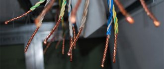
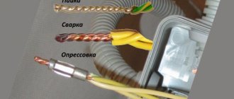
Connections and connections of grounding, protective conductors and conductors of the equalization and potential equalization system must be reliable and ensure continuity of the electrical circuit. It is recommended to make connections of steel conductors by welding. It is allowed to connect grounding and neutral protective conductors in indoor and outdoor installations without aggressive environments in other ways that meet the requirements of GOST 10434 “Electrical contact connections. General technical requirements" for class 2 connections.
Connections must be protected from corrosion and mechanical damage.
For bolted connections, provisions must be made to prevent contact loosening.
PUE requirements for the main grounding bus
The electrical installation rules in paragraph 1.7.119 define the basic requirements for installing the main grounding bus for networks up to 1 kW. In most cases, it is located in switchgear cabinets; if there are a large number of grounding conductors, a separate cabinet is used.
Tip #2. In some cases, it is permissible to install an open gas shutter near the switchgear if the room is closed. Access to such premises is limited to qualified service personnel only.
For grounding circuits of the TN-C type in switchgears, it is allowed to use a PE bus as a GShZ, the cross-section of which should not be smaller than the grounding wires that are connected to it. Copper is used for the main grounding bus; in extreme cases, steel is installed; the biggest mistake is to use aluminum strips. This is strictly prohibited due to the difference in resistance between contacts made of different metals. Such contacts heat up, conductivity decreases, and at high current loads, bolted connections can completely burn out.
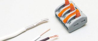
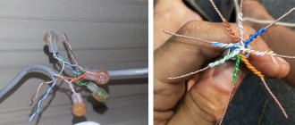
Connections are made dismountable using special tools, most often these are bolted fastenings with washers and nuts. The ends of the wires are crimped with copper lugs with holes for bolts and screwed onto the busbar. A symbolic sign is applied to the wall near the tire or a separate cabinet dedicated to it.
Clause 1.7.120 determines that for rooms with two or more separate inputs, each switchgear cabinet is equipped with a separate grounding bus. At transformer substations, their own busbar with a grounding loop is installed, the PEN conductor from which goes to the GShZ ASU (input switchgear) of the premises with electrical installations. The grounding buses on different switchgears must be connected by wire to equalize the potentials. The cross-section of the conductor should not be less than ½ of the larger wire that comes to one of the main switchgear in the ASU from the transformer substation.
To connect several busbars from different ASUs, it is allowed to use metal structures for various purposes if they are non-separable and have continuous electrical contact. In this case, it is necessary to take into account the requirements of paragraph 1.7.123, which prohibits the use of the following as a PEN conductor:
- pipes of gas distribution systems;
- pipelines with flammable materials;
- designs of heating, water supply and sewerage systems;
- lead and metal sheaths of armored cables;
- cable supporting cable for electrical wiring.
Please note that this is a common mistake; it is possible and even necessary to ground these structures to the main grounding bus, paragraph 1.7.20. But paragraph 1.7.123 prohibits making direct connections of busbars on different cabinets using the listed designs. At first glance, grounding the cable and pipeline at the ASU GSHZ will ensure their direct connection, but when repairing or dismantling these systems, the circuit will be broken.
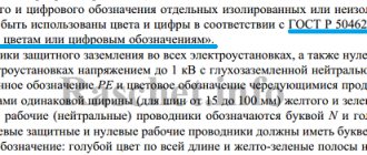
Therefore, only non-separable conductive structures are used; it is most reliable to install a stranded copper wire with yellow-green insulation corresponding to the designation of the grounding PEN conductor. In this case, the connection ensuring the distribution of the spreading potential will be autonomous and independent of other systems.
1.7.142
Connections of grounding and neutral protective conductors and potential equalization conductors to open conductive parts must be made using bolted connections or welding.
Connections to equipment that is subject to frequent disassembly or installed on moving parts or parts subject to shock and vibration must be made using flexible conductors.
Connections of protective conductors of electrical wiring and overhead lines should be made using the same methods as connections of phase conductors.
When using natural grounding conductors for grounding electrical installations and third-party conductive parts as protective conductors and potential equalization conductors, contact connections should be made using the methods provided for by GOST 12.1.030 “SSBT. Electrical safety. Protective grounding, grounding"
Features of connecting the main switch in the TN-C and TN-C-S circuits
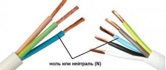
In circuits assembled according to these standards, the grounding wire is absent or is combined in certain sections of the wiring with a zero N-neutral; it is allowed to use a PEN bus as a ground wire. In the distribution board, all wires from the ground loop, power lines and ground from various building wiring groups are connected to this bus. In this case, the grounding bus is connected by a separate wire to the bus for lines with an insulated neutral N.
Thus, it is possible to use the steel cabinet body as the main ground bus
Connecting the main switch to the ASU located on power line poles
The peculiarity of this connection option is that the ASU cabinets are on poles, have their own grounding system and are very often connected to the house via a cable suspended by a cable.
In these cases, a wire from the grounding pole, a grounding line of a power transmission line, and a branch from a metal cable are connected to the GZSh. In addition, the main buses of the ASU of the pole and the ASU of the house are connected by a separate line. The cable is grounded on both sides, to the bus near the power line and to the bus in the ASU for the home.
1.7.143
Places and methods of connecting grounding conductors to extended natural grounding conductors (for example, pipelines) must be selected such that when disconnecting the grounding conductors for repair work, the expected touch voltages and the calculated resistance values of the grounding device do not exceed safe values.
Shunting of water meters, valves, etc. should be carried out using a conductor of the appropriate cross-section, depending on whether it is used as a protective conductor of the potential equalization system, a neutral protective conductor or a protective grounding conductor.
PUE (seventh edition)
Separate paragraphs of the PUE stipulate that switchgear and 20-750 kV open-type transformer substations must be equipped with lightning rods. For some types of structures, the absence of special lightning protection is allowed, but only under the condition of a limited duration of thunderstorms throughout the year (no more than 20 hours).
The same closed structures require lightning protection only in areas with a thunderstorm duration index of more than 20.
Grounding
In the case where closed buildings have a metal roof, lightning protection is carried out using grounding devices connected directly to the roofing. If the roofing is made of reinforced concrete slabs, then if there is good contact between the individual elements of the building, grounding through the reinforcement included in them is allowed.
Protection of closed switchgear and transformer substations buildings is carried out either using rod-type lightning rods or by laying a special metal mesh.
The use of these protective structures is considered justified only in cases where lightning protection is installed on the reinforced concrete roof of buildings, the slabs of which do not have an electrical connection with the ground.
Rod and mesh protection
When installing standard lightning rods on a protected structure, at least 2 down conductors are laid from each of them towards the grounding conductor, located on different sides of the building. A specially designed lightning protection mesh, laid on top of the roof on special holders, is made of steel wire with a diameter of 6-8 millimeters.
1.7.145
It is not allowed to connect switching devices in PE
- and
PEN
conductors, with the exception of cases of power supply to electrical receivers using plug connectors.
It is also allowed to simultaneously disconnect all conductors at the input to electrical installations of individual residential, country and garden houses and similar objects fed by single-phase branches from overhead lines. In this case, the division of PEN
- conductor to
PE
- and - conductors must be done before the input protective switching device.
1.7.146
If the protective conductors and/or potential equalization conductors can be disconnected using the same plug connector as the corresponding phase conductors, the socket and plug of the plug connector must have special protective contacts for connecting the protective conductors or potential equalization conductors to them.
If the body of the socket outlet is made of metal, it must be connected to the protective contact of that socket.
We will talk about artificial grounding in the TN system.
The first is connecting the circuit to the wrong point in the electrical installation where it should be connected. For example, the ground loop is connected directly to a washing machine or some machine tool.
In fact, the circuit must be connected to the main ground bus.
The second is to use, instead of a circuit, water supply, gas supply, heating pipes, or some other incomprehensible metal structures that people think could be a grounding circuit. Such structures may not always have a grounding loop.
Third, there is no connection between the 0 conductor and the grounding device. This also includes the installation of separate circuit breakers in the 0 conductor, which can turn off and the connection between the grounding device and the neutral conductor will be lost and there will no longer be protective grounding.
Fourth - the use of all kinds of objects buried in the ground as grounding devices; buckets, fittings, metal fences. Used as a worker ground 0. A metal fence around a house does not make a good loop.
DIY grounding welding
So, before us are three grounding conductors in the form of pieces of pipe or metal corner 1.5 meters long. Let's find enough space to install the grounding. A place near the house where it will always be damp and humid would be a great option. It is not recommended to do grounding in close proximity to an existing water supply, as this may negatively affect its durability.
Let's take a sledgehammer and hammer three metal corners into the ground in the shape of a triangle. The distance between the corners should be at least one meter, their depth 1.5 m. Then, using a welding inverter and an electrode with a diameter of 3 mm, we weld a metal strip on top of the corners (connect the corners together).
Using the same strip, we will lead a bus from grounding into the house, to which electrical appliances could be connected. Thus, despite all the apparent complexity, making grounding with your own hands is not so difficult.
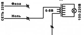
To check grounding, you can use a phase from the mains and an artificial zero created from grounding. The less the voltage “sags” when connecting the load to ground, the better its resistance and operating efficiency.
Share on social networks