We scribbled down some comments.
There was a commission on the newly built panel, they wrote several comments, help us figure out whether they are all justified.
Maintain the distance between 0.4 kV cable lines laid in the basement in accordance with the requirements of Table No. 2.3.1 PUE. Table No. 2.3.1 shows the shortest distance for cable structures, but can the basement of a residential building be classified as such?
Connect waste collection chambers to the emergency lighting network based on the requirements of clause 4.8 “SP31-110-2003”. It seems like a correct requirement, the only reason why no one noticed this at the project stage, and as I understand the joint venture is of a recommendatory nature?
organizer wrote: Table No. 2.3.1 shows the shortest distance for cable structures, but can the basement of a residential building be classified as such?
complex issue. Most likely no.
A cable structure is a structure specifically designed to house cables.
organizer wrote: It seems like a correct requirement,
There are no ideal projects. I, as a designer, officially declare this to you.
organizer wrote: The joint venture, as I understand it, is advisory in nature?
why suddenly? The document is the most valid.
organizer wrote: Ie. Ground the panel door, is this necessary?
Well, of course! Is it difficult for you to make a door-body jumper from yellow-green PV-3 with bolts?
Alexiy wrote: why suddenly? The document is the most valid.
Somewhere I came across that the joint venture is not mandatory, although I may be mistaken.
Alexiy wrote: well, of course! Is it difficult for you to make a door-body jumper from yellow-green PV-3 with bolts?
There is not a door to the ASU, but the entrance door to the switchboard is meant.
organizer wrote: Somewhere I came across that the joint venture is not mandatory
It is the joint venture that is not mandatory, since it does not have legal force, but all the requirements, GOSTs and SNiPs collected there are very mandatory.
Alexiy wrote: The cabinet door/panel is cleverly connected with a jumper
Only if any electrical equipment is installed on the door.
the door is connected in any case and it doesn’t matter whether something is installed on it or not. Just like when you open a drawer, you still touch the door
amidant wrote: the door is connected in any case
And is there a standard regarding this?
avmal wrote: Only if any electrical equipment is installed on the door.
If the door to the electrical room is metal. A grounding strip is welded to the box. And from the strip to the door there is a PV3 wire with lugs. As well as ventilation holes and, accordingly, inscriptions and signs.
Bladiclab wrote: And from the strip to the door there is a PV3 wire with lugs.
I've never seen it. PUE clause 1.7.77 does not require this.
So in general, is there a standard that the entrance door to the panel room must be grounded? This is not the first time we are renting out a house, this is the first time we have had such a requirement. The inspector referred to clause 1.7.83 of the PUE, but it was about DSUP, but in fact they didn’t do any DSUP in the panel room, because there was nothing like that in the project. And the inspector didn’t write anything about the absence of DSUP in the control room.
organizer wrote: should the front door in the panel room be grounded?
I repeat for the 3rd time: read carefully the PUE clause 1.7.77
1.7.77. It is not necessary to intentionally connect to the source neutral in a TN system and to ground in IT and TT systems:
1) housings of electrical equipment and devices installed on metal bases: structures, switchgears, switchboards, cabinets, frames of machines, machines and mechanisms connected to the neutral of the power source or grounded, while ensuring reliable electrical contact of these housings with the bases;
2) structures listed in 1.7.76, while ensuring reliable electrical contact between these structures and the electrical equipment installed on them, connected to the protective conductor;
Here is the door to the 0.4 kV ShchSN room of the 500 kV switchgear building: outside view: inside view: as you can see, no flexible conductors.
Source
What color are the protective grounding conductors painted?
In this article, we will talk about what color the protective grounding conductors in accordance with the standards.
The following are excerpts from regulatory documents:
According to the PUE clause 1.1.29, the color of the protective grounding conductors is specified in GOST R 50462 “Identification of conductors by means of colors and alphanumeric designations”.
According to GOST R 50462 clause 5.3.2 and GOST 33542-2015 clause 6.3.2, protective conductors must be painted yellow-green :
According to PTEEP Chapter 2.7 “Grounding devices” clause 2.7.7:
Please note that the PTEEP states that grounding conductors must be painted black to protect against corrosion, that is, this paragraph is applicable only for grounding conductors that are susceptible to corrosion, for example, a regular steel strip (tape) without any applied protective coating (hot-dip galvanizing, copper coating, etc.).
Accordingly, in other cases, the protective grounding conductors must be painted yellow-green, as indicated in the PUE clause 1.1.29 and GOST R 50462 clause 5.3.2.
Also, for your reference, I provide Table 54.1 from GOST R 50571.5.54-2013 indicating the most common materials of protective grounding conductors in terms of corrosion resistance.
Source
Is it necessary to ground the doors of switchboards and cabinets?
Is it necessary to ground the doors of switchboards and cabinets? Where is this described in regulatory documents?
1.7.144. The connection of each open conductive part of the electrical installation to the neutral protective or protective grounding conductor must be made using a separate branch. The series connection of exposed conductive parts into the protective conductor is not permitted. The connection of conductive parts to the main potential equalization system must also be made using separate branches. The connection of conductive parts to an additional potential equalization system can be done using either separate branches or connection to one common permanent conductor.
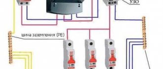
Are there clamps for PE conductors on the switchboard doors? What is the protection class of the shield against electric shock?
GOST R 51778-2001 DISTRIBUTION BOARDS FOR INDUSTRIAL AND PUBLIC BUILDINGS 6.4.3 If electrical appliances are installed on the door of a class I panel, then the door should be additionally connected to the conductive housing with a flexible copper jumper.
GOST R 51732-2001 INPUT AND DISTRIBUTION DEVICES FOR RESIDENTIAL AND PUBLIC BUILDINGS 6.7.2 In ASUs of all types of class I, open conductive parts must have electrical connections among themselves and with the zero protective bus PE in accordance with 6.3.13 and meet the requirements of 6.7.5. In single- and multi-panel ASUs, these connections must withstand short-circuit currents in accordance with 6.8.2. If electrical devices are installed on the door of the ASU, then the door should be connected to the conductive frame or shell with a flexible copper jumper.
Source
Color of conductors in the cable according to PUE 7, GOST R 50462 and GOST 31996
clause 1.1.29. For color and digital designation of individual insulated or non-insulated conductors, colors and numbers must be used in accordance with GOST R 50462 “Identification of conductors by colors or digital designations”.
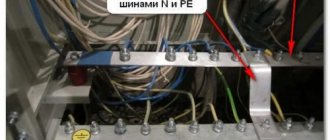
Protective grounding conductors in all electrical installations, as well as neutral protective conductors in electrical installations with voltages up to 1 kV with a solidly grounded neutral, incl. tires must have the letter designation PE and a color designation with alternating longitudinal or transverse stripes and the same width (for tires from 15 to 100 mm) in yellow and green .
Zero working (neutral) conductors are designated by the letter N and the color blue . Combined neutral protective and neutral working conductors must have the letter designation PEN and color designation: blue along the entire length and yellow-green stripes at the ends
According to GOST R 50462
(GOST R 50462-2009 (IEC 60446:2007) Basic principles and safety principles for the human-machine interface, implementation and identification. Identification of conductors by means of colors and alphanumeric designations)
In accordance with Table A.1 of Appendix A. (read the original table)
AC electrical circuit
- Single-phase phase conductor - Brown
- Phase conductor 1 of three-phase circuit - Brown
- Phase conductor 2 three-phase circuit - Black
- Phase conductor 3 three-phase circuit - Gray
- Grounded phase conductor of a single-phase circuit - Blue
- Grounded phase conductors of a three-phase circuit - Blue
- Neutral conductor - Blue
DC electrical circuit
- Positive Terminal - Brown
- Negative Terminal - Gray
- Grounded Positive Pole Conductor - Blue
- Grounded negative pole conductor - Blue
- Middle conductor - Blue
Protective conductors and conductors combining the functions of protective conductors:
- Protective conductor - Yellow - green
- PEL conductor - Yellow - green
- PEM conductor - Yellow - green
- PEN conductor - Blue
- Protective potential equalization conductor - Yellow - green
According to GOST 31996
(GOST 31996-2012 Power cables with plastic insulation for rated voltage 0.66; 1 and 3 kV. General technical conditions)
In accordance with table 4, clause 5.2.1.10 (read the original table).
When producing cables according to this GOST, the colors in the cores will be as follows:
- Twin cable (2 cores) - Gray* and Blue
- Three-core cable (3 cores) - Gray* , Blue and Green- Yellow
- or three-core cable (3 cores) - Gray* , Brown
and
Black - Quad cable (4 cores) - Grey*, Brown , Black
and
Green- Yellow** - or four-wire cable (4 cores) - Grey*, Brown , Black
and
Blue - Five-core cable (5 cores) - Grey*, Brown , Black, Blue
and
Green- Yellow**
Note: * - or natural color; **- as agreed with the customer
Source
Comments
If necessary, then how correctly (only the door frame is enough, or is the door leaf also needed) and on the basis of what document?
User, August 29, 2013
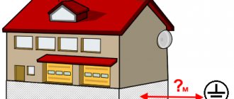
Is it necessary to ground (for example, by connecting to the main potential equalization system) metal entrance doors to the entrances of residential buildings? The doors are equipped with intercom devices (intercom with an electromagnetic lock), powered by a voltage of 12-15 V through power supplies. Power supplies (PSUs), in turn, are located either in floor panels on the 1st floor or in metal boxes in the entrance vestibules. The housings of floor panels and metal boxes are naturally grounded: floor panels - by connecting to the PE conductor of the apartment power distribution line, metal boxes with power supplies - to the PE conductor of the 220 V network that powers the power supplies themselves.
If necessary, then how correctly (only the door frame is enough, or is the door leaf also needed) and on the basis of what document?
Sergey, here is the expert’s answer to your question.
Additional potential equalization provides for the connection of all metal building and industrial structures, which include doors and gates. If doors and/or gates are equipped with an electric drive or any electrical receivers (electrical devices) are installed on them, then they must be connected to a protective grounding system.
Source
Grounding in a private house
To bookmarks
General requirements
Grounding is one of the main measures of protection against electric shock.
This article provides detailed, step-by-step instructions on how to make grounding in a private house with your own hands.
First, let's define what grounding is?
According to the PUE, Grounding is an intentional electrical connection of any point in the network, electrical installation or equipment with a grounding device. (clause 1.7.28.)
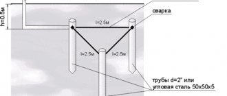
As a grounding device, are used that are driven vertically into the ground (the so-called vertical grounding conductors ) and metal rods or metal strips that, by welding, connect the vertical grounding conductors to each other (the so-called horizontal grounding conductors ).
Vertical and horizontal grounding conductors together form a grounding loop , this loop can be closed (Figure 1) or linear (Figure 2):
The grounding loop must be connected to the main grounding bus in the incoming electrical panel of the house using a grounding conductor , which, as a rule, is the same metal strip or rod that is used as a horizontal grounding conductor.
The protective grounding of a private house will have the following general form:
In turn, the combination of the grounding loop and the grounding conductor is called a grounding device.
A closed grounding loop is usually made in the shape of a triangle with sides of 2 to 3 meters (depending on the length of the vertical grounding conductors); it is important that the distance between the vertical grounding conductors is not less than their length (see Fig. 1). A closed contour can also be made in other shapes, for example oval, square, etc. In turn, a linear circuit is a series of vertical grounding electrodes, 3-4 in number, lined up in a line, and, as in the case of a closed circuit, the distance between them in a linear circuit must be no less than their length, i.e. from 2 to 3 meters (see Fig. 2).
Note: A closed ground loop is considered more reliable because even if one of the horizontal grounding conductors is damaged, this circuit remains operational.
Horizontal and vertical grounding conductors must be made of black or galvanized steel or copper (clause 1.7.111. PUE). Due to their high cost, copper grounding conductors are, as a rule, not used. Also, grounding conductors should not be made from reinforcement - the outer layer of the reinforcement is hardened, which disrupts the distribution of current across its cross-section, and it is more susceptible to corrosion.
Vertical grounding conductors are made from:
- round steel rods with a minimum diameter of 16mm (recommended: 20-22mm)
- steel corners with dimensions of at least 4x40x40 (recommended: 5x50x50)
The length of vertical grounding conductors should be 2-3 meters (at least 2.5 m is recommended)
Horizontal grounding conductors are made from:
- round steel rods with a minimum diameter of 10mm (recommended: 16-20mm)
- steel strip measuring 4x40
The grounding conductor is made of:
- round steel rod with a minimum diameter of 10mm
- steel strip measuring at least 4x25 (recommended 4x40)
It is recommended to use the same material as a grounding conductor that was used as a horizontal grounding conductor.
2. Grounding installation procedure:
STEP 1 — Select a location for installation
The installation location is selected as close as possible to the main electrical panel (input panel) of the house in which the main grounding bus (GZSh), also known as PE bus, is located.
If the input electrical panel is located inside the house or on its external wall, the grounding loop is mounted near the wall on which the electrical panel is located, at a distance of approximately 1-2 meters from the foundation of the house. If the electrical panel is located on an overhead power line support or on a remote rack, the grounding loop can be mounted directly under it.
At the same time, you should not place (use) grounding electrodes in places where the ground is dried under the influence of heat from pipelines, etc. (clause 1.7.112 PUE)
STEP 2 - Excavation
We dig a trench in the shape of a triangle - for installing a closed grounding loop, or a straight line - for a linear one:
The depth of the trench should be 0.8 - 1 meter
The width of the trench should be 0.5 - 0.7 meters (for the convenience of welding work in the future)
The length of the trench depends on the selected number of vertical ground electrodes and the distances between them. (For a triangle, 3 vertical earth electrodes are used, for a linear circuit, as a rule, 3 or 4 vertical earth electrodes)
STEP 3 — Installation of vertical grounding conductors
We place vertical grounding rods in the trenches at the required distance from each other (1.5-2 meters) and then drive them into the ground using a hammer drill with a special attachment or a regular sledgehammer:
The ends of the grounding conductors must first be sharpened for easier entry into the ground:
As already written above, the length of the vertical ground electrodes should be approximately 2-3 meters (a minimum of 2.5 meters is recommended), and it is necessary to drive them into the ground for the entire length, so that the upper part of the ground electrode protrudes above the bottom of the trench by 20-25 cm :
When all vertical grounding rods are driven into the ground, you can proceed to the next step.
STEP 4 — Installation of horizontal grounding conductors and grounding conductor:
At this stage, it is necessary to connect all vertical grounding conductors to each other using horizontal grounding conductors and weld a grounding conductor to the resulting grounding loop, which will come out of the ground to the surface and is intended to connect the grounding loop to the main grounding bus of the input electrical panel.
Horizontal and vertical grounding conductors are connected to each other by welding, and the junction must be welded on all sides for better contact.
IMPORTANT! The use of bolted connections is not allowed! Vertical and horizontal grounding conductors forming the grounding loop, as well as the grounding conductor at the point of its connection to the grounding loop, must be connected by welding.
Welded seams must be protected from corrosion, for which the welding areas can be treated with bitumen mastic.
IMPORTANT! itself must not be painted! (clause 1.7.111. PUE)
The result should be something like this:
STEP 5 - Fill the trench with soil.
Everything is simple here, we fill the trench with the mounted grounding loop with earth, so that there is at least 50 cm of soil above the loop, as already mentioned above.
However, there are some subtleties here too:
IMPORTANT! Trenches for horizontal grounding conductors must be filled with homogeneous soil that does not contain crushed stone and construction waste (clause 1.7.112. PUE).
STEP 6 — Connecting the grounding conductor to the main electrical panel (input device).
Finally, we have come to the final stage - grounding the electrical panel of the house, for this we perform the following work:
We bring the grounding conductor to the electrical panel, so that there is about 1 meter left to the electrical panel; if the input panel is located in the house, it is advisable to bring the grounding conductor into the building. In this case, the following identification mark must be provided at the points where grounding conductors are inserted into buildings (clause 1.7.118. PUE):
The grounding conductor itself, located above the surface of the earth, must be painted; it must have a color designation with alternating longitudinal or transverse stripes of the same width (from 15 to 100 mm) of yellow and green colors. (Clause 1.1.29. PUE).
We weld a bolt to the end of the grounding conductor on the side of the electrical panel, onto which we connect a flexible copper wire with a cross-section of at least 10 mm2, which should also be yellow-green in color. We connect the second end of this wire to the main grounding bus, for which a PE bus should be used inside the input device (input electrical panel of the house) (clause 1.7.119. PUE).
IMPORTANT! The main grounding bus should, as a rule, be copper. It is allowed to use a main grounding bus made of steel. The use of aluminum tires is not permitted. (Clause 1.7.119. PUE).
As a result, the grounding diagram of the house shield should look like this:
NOTE: the electrical panel grounding diagram shown refers to the TN-CS grounding system.
The following protection devices are installed in this electrical panel:
1 - Automatic switches - to protect electrical wiring from short circuits and overloads.
2 - SPD - a device for protecting the network from lightning or surge surges in the network.
3 - RCD - a device for protecting people from electric shock.
IMPORTANT! The grounding loop must be connected only to the PE bus of the input panel and not to any other place in the electrical network. In the input electrical panel, the working zero (N) must also be connected to the PE bus (as shown in the diagram), thus re-grounding it. After the introductory panel, the working zeros from the N bus and the protective zeros from the PE bus should not be connected!
In this case, the wiring in the house must be carried out with a three-core cable: the yellow-green cable core is connected to the PE bus and is used as a ground wire, the blue or light blue wire is connected to the N bus and serves as a working zero, and finally the third wire is connected through a circuit breaker per phase . See an example of a three-wire wiring diagram here.
Conductors of the potential equalization system are also connected to the PE bus .
That's all, but it must be remembered that protective grounding is only one component of a set of measures that provide reliable protection against electric shock. Other components include:
- automatic power off - provided by protection devices , primarily such as RCDs and circuit breakers .
- potential equalization - read more about the potential equalization system here .
Was this article useful to you? Or maybe you still have questions ? Write in the comments!
Didn’t find an article on the website on a topic that interests you regarding electrical engineering? Write to us here. We will definitely answer you.
↑ Up
5
https://elektroshkola.ru/zazemlenie/zazemlenie-v-chastnom-dome/
Requirements for an electrical panel door
To fully commission the electrical panel, it is necessary to fully comply with the requirements set out in the profile standards. This also applies to doors that are installed here. Basic installation rules, as well as technical parameters, are set out in the “Rules for Electrical Installations”, as well as SN 31-110-2003. The latest standard deals with the rules for the design and installation of electrical installations for public and residential buildings.
List of basic requirements
Before installing electrical panel doors, we recommend reading the requirements below.
Requirements, standards and recommendations for installing an electrical panel on a pole
Installation of the electrical panel on the pole is carried out in accordance with the requirements of PUE-7. Paragraph PUE 1.5.36 states that a switching device or fuses must be installed before the meter. The distance between them and the meter cannot be more than 10 meters. The distance to the shield itself from the ground should be no more than 1.7 meters. The minimum is 80 cm, in some cases the installation height can be reduced to 40 cm. Automatic protective switches can only be installed after the meter.
Energy company standards for installing a panel on a pole
Energy companies recommend following these rules when installing an electrical panel on a pole:
- Reliable, stable support is required;
- the cabinet with the metering device installed inside must be locked;
- the shield must have a transparent window for quick readings;
- The metering unit cabinet, rack, and neutral wire are subject to mandatory grounding.
Power engineers also recommend installing a pulse electric meter in the panel with a controller that transmits data to the transformer substation automatically.
Expert requirements and recommendations for installing an electrical panel
Experts recommend observing height requirements; do not place the shield on a pole higher than 1700 mm from the ground level. In practice, the height can be increased to 2.5 meters if we are talking about sparsely populated villages or gardening partnerships.
It is also necessary to use a VVG cable for descent to the switchboard and entry into the house by air (for overhead power lines, a self-supporting insulated wire, SIP, is suitable). It must be secured to supports and protected with special pipes. Protective pipes are also used for underground entry into the house. To pull the cable inside, it is tied to a cable.
Not only a metering device is installed in the switchboard, but also an input switch (before the meter), circuit breakers (after it) and an SPD (surge protection device).
What kind of door can be installed in a transformer substation?
One of the requirements for arranging a substation specifies what technical doors should be installed in the room and what requirements they should meet.
Of course, doors for transformer rooms are selected only on the basis of existing rules, otherwise they may not be accepted by the relevant authorities carrying out control.
Requirements for technical doors for a substation
At the moment, the following requirements are accepted and actively used:
Fire doors to a transformer substation must comply with standard EI 60. It states that the door leaf must withstand direct contact with an open fire for 60 minutes.
Requirements for doors to the electrical room
The electrical control room, like any other technical room, has a number of requirements for arrangement, which relate to the distance of passages, ceiling heights, as well as entrance door blocks. Doors for electrical rooms must fully comply with the current SN 31-110-2003, and the developed rules for the design of electrical installations. Only compliance with such criteria gives the right to install a door into the room.
Doors to the electrical room requirements pue
Requirements for doors in the electrical room:
According to the basic requirement, the door must be all-metal, however, options for installing wooden panels trimmed with metal sheets are allowed. In this case, it is very important to comply with the fire safety level. That is, the door must withstand open fire for 0.75 hours.
Installation of an introductory board on a pole
The entire process of installing an electrical panel on a street pole includes the following operations:
- Preparatory markings on the pole, which help determine the required installation location in accordance with the height requirements (0.8-1.7 m).
- Fixing the necessary equipment. The fastening bracket is used to grasp the post, and its two ends are brought out in the direction of the top cover of the shield. On the front side it is connected by a channel. The lower edge of the shield is secured in a similar way.
- The housing is grounded.
- Automatic machines and protective devices inside the shield are being assembled.
Shield installation
Installation of the shield for installing the meter can be done on a separate support, on a power line pole or on a stand made of scrap materials. It is important that it is stable and level so that the shield can be fixed level and secured with through bolts.
Read also: Designation of welds on construction drawings
According to the standard, the height of the shield cannot exceed 1.7 meters, but network operators may require installation at a height of 2.5-3.0 meters. In this case, when choosing supports and fastenings, you must also take into account the increased wind load.
Inputting wiring and connecting machines
For input into the switchboard, it is necessary to provide intermediate insulators that prevent damage to the insulation on the input cable.
As for the composition of the street electrical panel, it includes:
- Input machine with 2 poles (if the network is single-phase) and with 3-4 poles (if 3-phase);
- Differential circuit breaker for fire protection of the network (RCD rated 100-300 mA);
- An electrical energy meter selected in accordance with the connected power;
- Additionally, you can install a voltage control relay, surge arrester (SPD) or SPD (surge protection device), which protects not only from switching surges, but also from overvoltages caused by electrical discharges in the atmosphere (thunderstorm).
Also, the electricity supplier may recommend an insulated shield or the need to install a modular thermostat in it to maintain positive temperatures inside the housing in winter.
Shield grounding
The PE and N neutral buses are placed in the shield, combining them with a jumper, which allows you to combine the neutral and grounding conductors. The metal housing is grounded by a connection to the PE bus. A repeated grounding device is also connected to it (a copper wire with the same cross-section as for the input phase conductor is used for connection).
The grounding device itself is made of steel rods with a diameter of 16 mm or corners of the same cross-section. The elements are welded together with a 4x10 mm steel strip, and the entire structure goes deep into the ground at the location where the meter is installed.
Standard requirements for transformer substation gates
The manufacture of gates for transformer substations takes into account all established standards and regulatory documents. Only such compliance allows the facility to be put into operation. The following are considered standard parameters of finished structures:
GOST transformer substation gate
One of the main parameters that gates must meet is the fire resistance class. According to the current GOST, the minimum time for gate resistance to open fire is at least 35 minutes.
One of the main tasks performed by gates for transformer rooms is to reduce the likelihood of fire spreading. Gates with louvres and nipple openings must be fire resistant.
For this purpose, during the manufacturing process, it is recommended to use a frame structure covered with 2 mm steel sheets. The internal filling of the canvases is carried out with fiberglass material, which increases the level of safety of the structure.
Ensuring normal air exchange in the transformer room can be achieved by mounting ventilation grilles on the surface of the gate. The dimensions of such grilles are calculated based on the area of the room and the power of the installed equipment. Installation work on the installation of transformer gates can be carried out by companies or persons who have the appropriate permit.
Criteria for choosing a door to the electrical room
The arrangement of the electrical panel is carried out on the basis of accepted standards and norms, for which clear regulations have been established by the relevant authorities. The choice of door to the room and its parameters are prescribed in documents such as SN 31-110-2003 and “Rules for the construction of electrical installations”.
Doors electrical panel requirements pue
In order to quickly put a technical room into operation, it is necessary to strictly adhere to the basic rules when designing it.
Basic requirements that doors in an electrical room must meet:
The specified list of compliance criteria is only a small part of the total list. It is important to pay attention to such points as the presence of a window and a ventilation system. In the case of spruce, these elements are missing, then you need to select doors with a ventilation grille or double-glazed windows.
Source