What is a ground loop
To understand what a loop grounding system is, you should imagine it as a system consisting of metal rods, strips connecting them and a set of copper connecting conductors. This prefabricated structure ensures reliable contact of the electrical installation’s current-conducting housing with the actual ground (soil).
When clarifying the question of what are grounding loops, it should be understood that their main component is a single electrode of a suitable size and cross-section, driven into the ground to a certain depth. To create a distributed loop system according to current technical requirements, a group of pins connected to each other by metal strips must be used.
How it works
To make it clear to everyone why grounding loops are needed, let’s look at the principle of operation of a composite structure. The protective ground loop works as follows:
- Due to high-quality installation of grounding conductors and good contact with the ground, the metal distributed system provides ideal conditions for emergency currents to flow into the ground.
- Thanks to this, the potential dangerous to humans that appears on the body of electrical equipment in emergency mode (when the insulation of a phase wire is broken, for example), is sharply reduced.
- Reliable flow of current into the ground is ensured by the low contact resistance of the ground electrode, which is part of the protective circuit.
The appearance of significant emergency currents leads to the operation of protection devices installed in the supply circuits (both circuit breakers and fuses).
As a result, the power supply is completely turned off, preventing possible negative consequences. When connecting a ground loop, the main focus is on creating conditions that ensure effective contact of both pins and strips with the ground.
Influence of soil on resistance Rз
Grounding calculation
It has been practically proven that the resistance of the grounding device is largely determined by the condition of the soil at the location of the ground electrode. In turn, the characteristics of the soil in the area of protective work depend on the following factors:
- Soil moisture at the work site;
Additional Information. When assessing moisture content, you should know that shale and clay retain water well, while sandy soils, on the contrary, do not.
- The presence of rocky components in the soil, in which it is simply impossible to arrange grounding (in this case, you have to choose another place);
- Possibility of artificial soil moisture during particularly dry summer periods;
- Chemical composition of the soil (presence of salt components in it).
Depending on the composition of the soil, it can be classified as one or another type (see photo below).
Different types of soil
Based on the peculiarities of the formation of the resistance of the ground electrode, which suggests its decrease when moistened and the salt concentration increases, in case of emergency, portions of the wet chemical NaCl are artificially introduced into the soil.
Good soils from the point of view of grounding arrangement are loamy soils with a high content of peat components and salts.
What does grounding consist of?
The composition of the grounding system, according to its definition (see PUE), includes such mandatory elements as:
- The locking device itself is equipped on the basis of metal corners with a cross-sectional area of at least 100 mm square or individual pins with a diameter of about 20 mm.
- A set of special conductors (copper bars) that allow grounding electrical appliances in residential buildings.
Please note: Sometimes a grounding drain installed along the wall of a building is considered as a separate element (in lightning protection devices, for example).
Depending on their location relative to the building, protective structures can be external or internal. Let's consider how to arrange each of the presented types of circuits in order to achieve the best results.
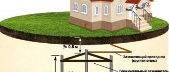
External contour
When arranging an external grounding loop, it is necessary to take into account the quality and composition of the soil at the location of its elements. The owners of a self-built house usually know what soil it sits on and can immediately determine how it affects conductivity. Otherwise, you will need the help of geodesy specialists.
When carrying out work yourself, it is important to know that soils are:
- purely clayey;
- loamy;
- peat;
- black soil;
- gravelly and rocky.
In real conditions, the first two classes of soils or their varieties (plastic loam, clay shales and the like) are most often found within a home plot. For various types of soils, their resistivities have the following values:
- Plastic clay and soft peat – 20-30 Ohm/meter.
- For loam containing ash and ash, as well as simple garden soil, this figure is 30-40 Ohm/meter.
- Chernozem soils and clay shales, as well as semi-solid clay, have a resistance close to 50-60 Ohm/meter.
From the point of view of organizing an external grounding loop, these soils are the most suitable, since their resistance to spreading is small.
Soils with high resistance values are represented by the following types:
- Semi-solid loam, sometimes defined as a mixture of clay and sand, as well as the so-called “wet sandy loam”, having an average value of 100-150 ohms/meter.
- Clay-containing gravel and wet sand – 300-500 Ohm/meter.
And such “hard” soils as rock, gravel and dry sand are completely unable to provide reliable grounding. Under these conditions, special measures are taken to reduce the resistance of the grounding loops at the location of the pins.
Additional information: They most often come down to artificially changing the composition of the soil. As an example, add a solution of table salt to it.
Another option that allows us to find a way out of this situation is to install deep grounding systems that reach layers of a “lighter” composition. But this approach to how to arrange external grounding is quite labor-intensive and will not be cheap.
Ground loop inside the object
When calculating the elements of the internal grounding loop, it is necessary to take into account that the conductive strip installed inside the building must cover the perimeter of each of the premises in it. All electrical installations and devices installed in them are connected to a grounding bus laid openly along the walls and close to the floor.
Please note: In small rooms (in residential apartments or private houses), instead of the control panel, a standard panel with a special strip is mounted. It is usually called the main ground bus (GZSh).
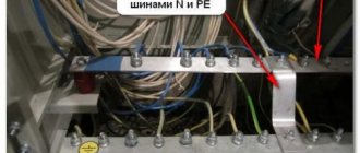
Grounding bus in the distribution panel
In these conditions, special attention is paid to such components as grounding conductors (connectors designed to connect household appliances and bathtubs directly to grounding).
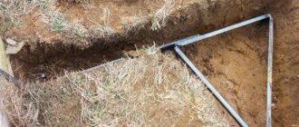
A separate contact of the shield (grounding strip) is connected either to an internal circuit arranged within the building, or through a long copper conductor to an external grounding system (as shown in the first photo of this article). Directly from it, copper busbars in the form of conductors are diverted towards various protected electrical installations and devices. Often, instead of a full-fledged shield, a separate contact strip “PE” is used, equipped directly at the entrance to a private house (the GZSh rail is shown in the photo below).
Main ground bus
Application of re-grounding in a classic TN system
Re-grounding is a critical element of a comprehensive electric shock protection system. It is used for grounding the neutral protective conductor of PE and PEN electrical networks up to 1000 Volts in a TN system with a solidly grounded transformer neutral.
Classical grounding systems are usually distinguished by the state of their neutral, which can be solidly grounded or isolated. In accordance with this feature, they are divided into two large groups and are designated by the appropriate combination of English letters. “T” stands for ground and “N” stands for neutral, which when written together symbolizes a grounded “zero.” In addition, these systems provide conductors and busbars, designated as PE (separate grounded connection) or PEN - combined working and protective busbar.
Depending on the chosen scheme, the permanently grounded neutral wire N can be either independent from the protective PE conductor, or can be connected to it, forming a PEN bus. In the first case, we get the TN-S system (“Separate” or separate gasket), and in the second - TN-C.
Please note: Here "C" stands for "Combined" or combined.
There is another option when two wires (protective and neutral) are combined on the substation side, and when entering the facility they are divided into a protective conductor PE and a functional bus N. This organization of the consumer protection system is called TN-CS and also requires the grounding of the neutral wire .
Installation technique
A competent approach to arranging a conservatory consists of choosing the correct location for it, as well as complying with the requirements of current regulations regarding basic installation work.
Choosing a location for the ZK
Before constructing a ground loop, it is important to select a location for placing its elements. Preferably, not far from home (it is usually planned to be installed at a distance of no more than 2 meters, which will allow you to benefit from the length of the conductors). Additional information: When choosing a site for grounding, first of all, you should take into account that this site is located on territory controlled by the owner.
The following areas are suitable for these purposes:
- garden plot (except potato beds);
- front garden or flower bed;
- park area directly adjacent to the house.
If the soil in the area adjacent to the building has a high resistivity, it is permissible to install a system of short-circuit pins at a more distant distance.
Please note: In this case, you will have to put up with unnecessary costs for purchasing copper busbars.
In any of the cases considered, when choosing a location for a security zone, all possible options for its use in the future (even in the very distant future) should be taken into account. This will allow you to avoid unnecessary costs of moving the structure in a situation where you need to set up a playground in this area, for example.
Installation of the ground loop
Depending on the selected site (its shape and size), various schemes can be used when installing the control panel. The pins in it can be located either in a line or in the form of a triangle.
Important! Regardless of the scheme used, the number of vertically driven ground electrodes must be at least three.
In the case when a triangular design is chosen, the procedure for arranging the protection zone is as follows:
- First, a platform of the appropriate configuration with sides of approximately 2.5-3 meters is marked at this place.
- Then a pit is dug out with dimensions slightly larger than those indicated by the markings.
- The pit dug in the ground should follow the shape of an isosceles triangle and have a depth of at least half a meter (with a width of about 50-70 cm).
- After this, three steel pins (pieces of reinforcement) are driven into the corners of the triangular pit with a slight deviation from the walls to a depth of at least 2 meters.
- And, in the end, they will all be connected to each other with steel strips (this is done by welding, which should be preferred in this situation).
The result should be a design similar to the one below.
Triangle ground loop
The cross-section of the grounding wires from the circuit should not be less than 12-16 mm square.
To save effort and time, you don’t have to completely dig out the pit for the pins. It will be enough to select the ground only from the grooves, into which the steel connecting strips are then laid. At the final stage of welding work, the finished ground electrode is sprinkled with a composition with low resistivity (ash or ash, for example). Over time, the salts contained in the additives will dissolve in the ground, which reduces the resistance to the spread of emergency current.
Parameters of ground electrodes (vertical arrangement)
When calculating vertical grounding loops, you must be guided by the following formula:
The values given in it are deciphered as follows:
R0 is the value of the calculated resistance of a single electrode in Ohms.
Req is the value of soil resistivity, already discussed earlier in the chapter on external soil resistance.
L is the length of an individual electrode included in the grounding system.
D – diameter or pin size corresponding to the cross-section.
T is the estimated distance from the conditional center of each electrode to the earth’s surface.
In order to obtain the required resistance value R0 (according to the PUE it should not exceed 30 Ohms), the variables included in the formula should be selected.
Please note: If, due to the characteristics of the soil in a given area, the installation of vertical rods is impossible, the resistance value is calculated using the formula for horizontal grounding rods.
Before calculating the ZK, it should be taken into account that installing a horizontal structure will require much more effort and time (as well as significant expenditure of copper material). In addition, grounding arranged in this way is very sensitive to weather conditions.
That is why it is believed that it is better to spend money on arranging vertical rods than to try to overcome the shortcomings of horizontal grounding systems.
How to calculate a ground loop: step-by-step instructions
The project is created in several stages.
Step #1. Material selection
The metal and its profile are selected according to the above table 1.7.104. In production, they use those materials that are available or easiest to purchase in a particular area. The main condition is to comply with the required cross-section.
Step #2. Design Definition
Here we ask:
- driving depth of vertical grounding conductors H;
- the distance between them D;
- their number N.
The calculation assumes their arrangement in a line, and not in a triangle, when the shielding area increases. But if necessary, this option can be easily recalculated.
The direction of the line is selected taking into account local conditions so that it does not intersect with other highways, for example, sewerage, water supply, gas supply.
The driving depth is determined experimentally on one control specimen. A hole 0.7 meters deep is dug for it and a test rod is driven into it.
At the same time, the effort expended and the features of the technology are assessed. If you pour a bucket of water into the hole and let it soak into the soil for at least half an hour, then driving it in will require less physical effort.
The recommended length for a prototype is usually 2-2.5 meters. In short, rods are made only for very dense soils.
The distance between the vertical electrodes is chosen as a multiple of their length: this makes it possible to better take into account the coefficients of mutual influence.
The number of vertical grounding rods determines the length of the connecting strip, taking into account the section of the supply to the house, and its characteristics are also included in the design calculations.
When the configuration and dimensions are selected, then proceed to the next stage.
Step #3. Calculation of electrical resistance of the selected circuit
Calculations using mathematical formulas allow a preliminary assessment of the assembled structure. If it meets the standard, then you can begin to manufacture it. Otherwise, adjustments are made to the circuit by increasing the number of electrodes, deepening them, or increasing the distances.
First, the resistance of single grounding conductors is calculated, taking into account their shape and method of burial.
When the calculation is completed and verified, we begin to determine special utilization factors. They take into account the degree of shielding and mutual influence of the electrodes.
I present their most common part in a table.
After determining the influence coefficients, you can proceed to the general calculation of the resistance of the grounding device. I'll give you the formula.
The result obtained may fall within the standardized 30 ohms or be higher. If it does not meet the requirements of the PUE, then something will need to be added to the design or the dimensions changed. After this, you need to make a new calculation and achieve a positive result.
Calculations can be done manually using formulas on paper or use the online calculator attached below.
Having calculated several options for the design of the grounding structure, you will remember its features well and understand the assembly technology. And this will help to avoid mistakes and create a reliable device for long-term operation.
Testing
Upon completion of installation work, it is necessary to test the grounding loop for standardized indicators. The test will require precise measuring instruments, which are not always available to the user.
Checking the ground loop
In the absence of the required equipment, you should use the simplest methods, one of which is described below (it is only suitable for a private home).
First, you need to take a fairly powerful load (such as an iron, for example, with a consumption of about 2-4 kW). Secondly, you need a special adapter with a regular socket at one end (the second of them is made in the form of two separate wires). Next, one of them should be designed as an insulated single contact, and a thick loop should be made at the end of the second.
After this, you need to connect the resulting loop to a free block on the grounding bus in the panel. A single insulated contact should be plugged into the phase terminal of the socket closest to it (under no circumstances should you violate the order of connecting the ends of the adapter to the phase and ground). After all these manipulations, the heating device will be connected to the supply circuit through the resistance of a homemade ground loop. Then you need to measure the voltage in the network using a multimeter with and without the iron on.
A small difference in the readings of the two described measurements means that the manufactured ground electrode is fully operational. If they differ very much, the circuit will have to be modified (increase the number of pins, for example).
We talked about how to check the presence of correct grounding with a multimeter in the corresponding article!
Why do experts argue?
Finally, we come to the most important thing. Why do experts argue, why do they give such different numbers?
First, you need to understand what kind of tests we are talking about. If we are talking about acceptance tests, then the answer should be found in the PUE, Chapter 1.8, Standards for acceptance tests, and if about operational tests, then we look for the answer in PTEEP, Appendix 3, Standards for testing electrical equipment and devices of consumer electrical installations.
Secondly, you need to understand the purpose of the ground loop. The grounding loop is for substations and distribution points above 1000 Volts, overhead power lines up to 1000 Volts and above 1000 Volts and electrical installations up to 1000 Volts.
What are the norms?
1. Grounding circuit for electrical installations with voltages up to 1000 Volts:
PUE, clause 1.8.39, table 1.8.38, clause 3 states: when measured in close proximity to a transformer substation, the resistance of the ground loop should be: 15, 30 or 60 Ohms, when measured taking into account natural grounding conductors and repeated outgoing grounding conductors lines: 2, 4 or 8 Ohms, respectively, for voltages of 660, 380 and 220 Volts.
PTEEP, Appendix No. 3, table 36 states: ground loop resistance - 15, 30 or 60 Ohms for network voltages 660-380, 380-220 and 220-127 Volts, respectively (three-phase / single-phase network), and when measured taking into account the connected repeated groundings should be no more than 2, 4 and 8 Ohms at voltages of 660, 380 and 220 Volts of a three-phase current source and voltages of 380, 220 and 127 Volts of a single-phase current source, respectively.
2. Grounding circuit for transformer substation and switchgears with voltages greater than 1000 Volts:
PUE, clause 1.8.39, table 1.8.38, clause 1 states: when measured in an electrical installation with a solidly grounded and effectively grounded neutral, there should be no more than 0.5 Ohm.
PTEEP, Appendix No. 3, table 36 states: when measuring in an electrical installation with a voltage of 110 kV and above, in networks with effective neutral grounding, the loop resistance should be no more than 0.5 Ohm.
In an electrical installation of 3 - 35 kV networks with an isolated neutral - 250/Ip, but not more than 10 Ohms, where Ip is the calculated ground fault current.
3. Grounding circuit of an overhead power line with voltage above 1 kV:
PUE, clause 1.8.39, table 1.8.38, clause 2 reads: Grounding devices of high-voltage line (VL) supports with soil resistivity, ρ, Ohm m: 100/100-500/500-1000/1000-5000 – 10, 15, 20 and 30 Ohms, respectively.
PTEEP, Appendix No. 31, table 35, paragraph 4 states:
A. For overhead power lines with voltages above 1000 V: Supports with a lightning protection cable or other lightning protection devices, metal and reinforced concrete supports of 35 kV overhead lines and the same supports of 3 - 20 kV overhead lines in populated areas, equipment grounding switches on supports of 110 kV and above : 10, 15, 20 or 30 Ohms with soil resistivity, respectively: 100, 100-500, 500-1000, 1000-5000 Ohm m.
B. For overhead power lines for voltages up to 1000 Volts: Overhead line support with lightning protection - 30 Ohm, Support with repeated neutral wire grounding - 15, 30 and 60 Ohm for supply network voltages 660-380, 380-220 and 220-127 Volts ( three-phase/single-phase network) respectively.
Bottom line
To summarize all that has been said, let’s pay attention to the recommendations shared by experienced craftsmen:
- Before starting installation work, it is advisable to prepare a drawing of the future structure, which may be needed during further operation. If it is available, it is easier to recall the layout of the pins in memory.
- Electrode segments can be driven in not only at the corner points of the triangle. They can be placed either in a line or in an arc. The main thing is that the total resistance to current flow created by the entire chain does not exceed 3-4 ohms.
- If it is greater than the normalized value, then the system will have to be modified by adding a couple more rods to it.
- If you have no experience in checking ground resistance yourself, it is best to invite a specialist.
After familiarizing yourself with all the intricacies of the process of assembling and testing the ZK, anyone can try to make it with their own hands.