Types of grounding systems
The following types of grounding are suitable for a private house and apartment:
- TN;
- IT;
- TT.
The first and most common TN system has subtypes - S and C S. In general, to decipher the abbreviations you need to understand several points.
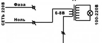
- By default, the first letter t indicates the operating principle of the power source.
- The second letter - N, T or I - indicates the principle of grounding and protection of open tap elements. T is prescribed if the circuit is grounded, N - if grounding is carried out by connecting to the neutral, and I - when the electrical equipment does not have electrical contacts, that is, the outlet is isolated. In the picture below you will see the grounding symbol and the corresponding diagram.
- The current State Standards have the concept of a neutral grounding conductor. It is relevant for systems with voltages up to 1 kV. The following are distinguished: earth (PE), neutral ground conductor (N) and connection of earth with zero (PEN).
Grounding devices for electrical installations with voltages up to 1 kV in networks with a solidly grounded neutral
1.7.100. In electrical installations with a solidly grounded neutral, the neutral of a three-phase alternating current generator or transformer, the midpoint of a direct current source, one of the terminals of a single-phase current source must be connected to the grounding conductor using a grounding conductor.
An artificial ground electrode designed to ground the neutral, as a rule, should be located near the generator or transformer. For intra-shop substations, it is allowed to place the ground electrode near the wall of the building.
If the foundation of the building in which the substation is located is used as natural grounding, the neutral of the transformer should be grounded by connecting to at least two metal columns or to embedded parts welded to the reinforcement of at least two reinforced concrete foundations.
In all cases, measures must be taken to ensure continuity of the grounding circuit and protect the grounding conductor from mechanical damage.
If the earth resistivity r >100 Ohm×m, it is allowed to increase the specified standards by 0.01r times, but not more than tenfold.
The specified repeated groundings are performed if more frequent groundings are not required under the conditions of protection against lightning surges.
Repeated grounding of the PEN conductor in DC networks must be performed using separate artificial grounding conductors, which should not have metal connections to underground pipelines.
Grounding conductors for repeated grounding of the PEN conductor must have dimensions no less than those given in table. 1.7.4.
The smallest dimensions of grounding conductors and grounding conductors laid in the ground
If the specific resistance of the earth is r >100 Ohm×m, it is allowed to increase the specified standards by 0.01 r times, but not more than tenfold.
Grounding devices for electrical installations with voltages up to 1 kV in networks with an insulated neutral
1.7.104. The resistance of the earthing device used for protective earthing of exposed conductive parts in an IT system must satisfy the following condition:
Upr is the touch voltage, the value of which is assumed to be 50 V (see also 1.7.53 );
As a rule, it is not necessary to accept a grounding device resistance value of less than 4 ohms. A grounding device resistance of up to 10 Ohms is allowed if the above condition is met, and the power of generators or transformers does not exceed 100 kVA, including the total power of generators or transformers operating in parallel.
Grounding devices in areas with high earth resistivity
1.7.105. Grounding devices of electrical installations with voltages above 1 kV with an effectively grounded neutral in areas with high earth resistivity, including in permafrost areas, are recommended to comply with the requirements for touch voltage (see 1.7.91).
| Cross-section of phase conductors, mm 2 | Minimum cross-section of protective conductors, mm |
| S ≤ 16 | S |
| 16 < S ≤ 35 | 16 |
| S>35 | S/2 |
Expert opinion
Viktor Pavlovich Strebizh, lighting and electrical expert
Any questions ask me, I will help!
26 PTEEP rules for the technical operation of consumer electrical installations, measurement of the resistance of the metal connection is carried out with the following frequency. If there is something you don’t understand, write to me!
What is electrolytic grounding?
Electrolytic grounding is a ready-made device that is used in rocky, sandy and permafrost soils. The kit includes a steel electrode, service well, filler, clamp and waterproofing tape. Where is electrolytic grounding used? The scope of application of the device is different. As a rule, it is used in places where it is not possible to install a grounding electrode to a depth of one meter. And also on soils that have high resistivity.
What does the system consist of?
The main element in the device is considered to be a hollow electrode, which has the shape of an L-shaped tube (in the figure it is marked with the number 1).
It is installed in the ground to a depth of one meter (soil thawing zone) and filled with a special mixture that includes mineral salts. 2 is a special well that makes work easier. 3 – clamp with which the electrode and grounding conductor are connected. 4 – waterproofing tape, which protects against moisture getting to the grounding and prevents corrosion.
The photo clearly shows what the ground electrode looks like:
What is a ground electrode and what can be used as a ground electrode?
What is a ground electrode?
GROUNDING LEADER - a conductive part (or a set of interconnected conductive parts) that is in contact with the ground directly or through an intermediate conductive medium.
What can a grounding conductor be made from?
1.7.109. The following can be used as natural ground electrodes: 1) metal and reinforced concrete structures of buildings and structures in contact with the ground, including reinforced concrete foundations of buildings and structures that have protective waterproofing coatings in non-aggressive, slightly aggressive and moderately aggressive environments; 2) metal water pipes laid in the ground; 3) casing pipes of boreholes; 4) metal sheet piles of hydraulic structures, water conduits, embedded parts of valves, etc.; 5) rail tracks of main non-electrified railways and access roads if there is a deliberate arrangement of jumpers between the rails; 6) other metal structures and structures located in the ground; 7) metal shells of armored cables laid in the ground. Cable sheaths can serve as the only grounding conductors when there are at least two cables. Aluminum cable sheaths are not allowed to be used as grounding conductors.
What cannot be used as a grounding conductor?
1.7.110. It is not allowed to use pipelines of flammable liquids, flammable or explosive gases and mixtures, and sewerage and central heating pipelines as grounding conductors. The specified restrictions do not exclude the need to connect such pipelines to a grounding device for the purpose of equalizing potentials in accordance with 1.7.82. Reinforced concrete structures of buildings and structures with prestressed reinforcement should not be used as grounding conductors, however, this restriction does not apply to overhead line supports and outdoor switchgear support structures. The possibility of using natural grounding conductors based on the density of currents flowing through them, the need to weld reinforcing bars of reinforced concrete foundations and structures, welding anchor bolts of steel columns to reinforcing bars of reinforced concrete foundations, as well as the possibility of using foundations in highly aggressive environments must be determined by calculation.
Requirements for artificial grounding conductors?
1.7.111. Artificial grounding conductors can be made of black or galvanized steel or copper. Artificial grounding conductors should not be painted. 1.7.112. The cross-section of horizontal grounding conductors for electrical installations with voltages above 1 kV should be selected according to the condition of thermal resistance at a permissible heating temperature of 400 °C (short-term heating corresponding to the duration of the protection and tripping of the circuit breaker). In case of danger of corrosion of grounding devices, one of the following measures should be taken: increase the cross-sections of grounding conductors and grounding conductors, taking into account their estimated service life; use galvanized or copper grounding conductors and grounding conductors. In this case, one should take into account the possible increase in the resistance of grounding devices due to corrosion. Trenches for horizontal grounding conductors must be filled with homogeneous soil that does not contain crushed stone and construction waste. Grounding electrodes should not be located (used) in places where the ground is dried out by the heat of pipelines, etc.
What not to use
When installing working grounding, some reinforced concrete structures cannot be used, since they may not meet safety requirements. For example, if the foundation is prefabricated, it is not suitable as a natural grounding conductor, since it is unlikely that it will be possible to create a continuous circuit.
In this case, it is better to use reinforcement from blocks located close to each other. Only after such an operation will it be possible to begin the construction of natural grounding.
If for some reason it is impossible to create such a circuit, it is better to abandon the use of a natural ground electrode and create an artificial circuit.
It is forbidden to use drain pipes (sewer pipes) as a grounding conductor, since they have weak electrical contact at the joints. Reinforced concrete racks in substations can only be used if they were made using special concrete (electrical concrete).
Types of grounding
In the classification of types of grounding there are two main types:
There are several subgroups: radio grounding, measuring, instrumental, control.
There is a certain category of electrical installations that will not work unless they are grounded. That is, the main purpose of constructing a grounding system is not to ensure operational safety, but to ensure the operation itself. Therefore, in this article we will not be interested in this species.
But this type is specially arranged to ensure the safety of electrical installations. It is divided into three categories depending on its purpose:
- Lightning protection.
- Protection against surge voltage (overload of current consumption line or short circuit).
- Protection of the electrical network from electromagnetic interference (most often this type of interference is generated from nearby operating electrical equipment).
We are interested in pulse overvoltage. The purpose of this type of grounding is the safety of operating personnel and the installation itself in the event of an accident or equipment breakdown. Typically, such a breakdown inside an electrical unit is a short circuit of the electrical circuit wire to the device body. The short circuit can occur directly or through any other conductor, for example, through water. A person who touches the installation body is exposed to electric current, because he becomes its conductor into the ground. In fact, it itself becomes part of the ground loop.
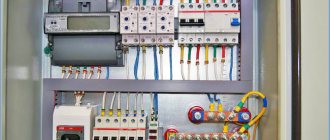
Grounding diagram in a private house
That is why, in order to eliminate such situations, the housing is grounded to a circuit located in the ground. At the same time, the activation of the grounding circuit is an impetus for the system of automatic machines, which immediately turn off the power supply to the equipment. All this is located in special power and distribution boards.
Ground resistance
There is such a term as resistance to current flow. For ordinary people it will be easier to perceive it as resistance to grounding. The whole point of this term is that the grounding circuit must work correctly within certain parameters. So resistance is the main one.
The optimal option for this value is zero. That is, it is best to use materials for assembling the circuit that have the highest electrical conductivity. Of course, there is no way to achieve the ideal, so try to choose those with the lowest resistance. These include all metals.
There are special coefficients that are used to determine the resistance of a grounding loop operated under different conditions. Eg:
in private housing construction, where networks of 220 and 380 volts (6 and 10 kV) are used, it is necessary to install a circuit with a resistance of 30 Ohms.
Attention! If a grounding circuit is used through the neutral of the transformer, then the resistance of the grounding circuit should be no more than 4 Ohms
- the installed gas pipeline system entering the house must be grounded with a 10 ohm circuit.
- lightning protection must have a resistance of no more than 10 ohms.
- Telecommunications equipment is grounded using a 2 or 4 ohm loop.
- Substations from 10 kV to 110 kV – 0.5 Ohm.
That is, it turns out that the greater the current power inside the equipment or devices, the lower the resistance should be.
Types of grounding and their purpose
Let's consider the types of grounding in electrical installations with their main features in the table.
| Types and subtypes of grounding | Peculiarities |
| TN | the most popular type of grounding system, which is a complex of pins driven vertically into the ground to the aquifer to a depth of over 2.5 m; the pins are connected by a cable (strip) into a common ground loop for a residential building; alternative name - solidly grounded neutral, i.e. the neutral is aligned with the ground along the entire length |
| TN-C | cheap, but outdated option with a high risk of danger: the working zero N is also a protective conductor PE, so if the N conductor breaks, the entire potential will transfer to electrical equipment, which can lead to fire or electric shock |
| TN-S | in new construction projects this subsystem is adopted, since it is the most reliable, and at the same time expensive (requires an additional conductor from the substation to the energy consumer); Structurally, TN-S includes a separate phase conductor, a neutral N and a protective conductor PE (the last two conductors are separate components, starting from a substation with a solidly grounded neutral) |
| TN-CS | this is a set of advantages of the subsystems described above; very simply implemented when reconstructing old types of neutral grounding; structurally consists of a TN-C system (up to the main distribution board), and then the neutral wire PEN diverges into an N-conductor and protective PE; and then the TN-S subsystem is organized; minus - full voltage is generated in the system when the PEN bus breaks, the problem is solved by installing protective voltage relays |
| TT | power supply is supplied through phase wires from sources with a solidly grounded neutral, grounding is installed directly at the consumer; connection of an RCD is mandatory |
| IT | The IT system does not use a solidly grounded neutral, the source zero is connected through a special device with high internal resistance, and the consumer has an additional neutral and protective grounding device installed (see Chapter 1.7 of the Electrical Installation Code); IT grounding method creates minimal interference |
Let us briefly summarize the types of grounding and their purpose:
- The IT supply system is suitable for special laboratories;
- The TT system is relevant for connecting temporary objects or mobile structures, for example, at a construction site;
- the TN-CS subsystem is most often chosen when reconstructing old buildings;
- TN-S - when designing new construction projects;
- TN-C is found predominantly in older housing stock and is currently not used due to high risks of fire and electric shock;
- The TN system is optimally suitable for residential buildings (pay attention to modern subsystems from this category).
Do not use water supply, heating, or gas pipes as protective grounding! Just like parts of metal fencing structures, in an emergency they provoke the appearance of full 220V voltage on their elements, which poses a threat to the health and life of humans and animals.
Operating conditions of ground electrodes
Grounding switches must be used in the conditions for which they are intended, depending on the type used. Maintenance and repairs must be carried out in accordance with the requirements of the manufacturer's operating manual and regulatory documents.
The specified work must be carried out with the involvement of trained and certified personnel, in compliance with the provided permit system.
Before connecting the equipment to the network, the following checks must be performed:
- cleanliness and integrity of insulators;
- tightness of threaded connections;
- presence of lubricant in the relevant components;
- sufficient contact pressure.
The proper operation of the device is first checked by performing several control turns on and off.
Maintenance involves regular inspections of its components, lubrication of rubbing parts, monitoring the condition of contacts, cleaning contacts and other elements. The frequency of maintenance is determined by the conditions and intensity of operation, but must be carried out at least once a year.
Performing calculations
At the design stage of the ground electrode, it is necessary to select its parameters so that the resistance of the device is within acceptable limits. To do this, a series of calculations are performed.
Soil resistance
The resistance to charge spreading for a single rod is calculated by the formula:
Ro = (Peq/2π*L) *{ln(2L/d) + 0.5 ln((4T + L)/(4T – L)}
If the electrode is placed in heterogeneous soil (2-layer), the resistance is calculated using the formula:
Peq = (Ψ*P1*P2*L)/( P1(L – H + tg) + P2(H – tg)), where
- Ψ – coefficient taking into account seasonality;
- P1 and P2 – specific resistivity of the first and second layers of soil, Ohm/m;
- H – thickness of the top layer, m;
- T – depth of immersion of rods;
- Tg – depth of the vertical pin (distance from the top of the ground electrode to the surface of the earth).
Dimensions and distances for ground electrodes
The minimum length of the rod is 2.5 m. If this condition is met, the base of the electrode with a 100% guarantee will be below the freezing mark of the soil, where acceptable resistance to charge spreading is maintained all year round.
The method for calculating the number of rods depends on what the ground electrode consists of.
If only from vertical electrodes, use the formula:
No = Ro *Ψ/Rн, where
Rн – resistance to spreading recommended by standards.
If the structure has horizontal elements, the number of rods is equal to:
N = Ro/( Rв*ηв), where
ηв – grounding conductor utilization coefficient, taking into account the mutual influence of the electrodes on each other.
In a linear design it is higher, so the calculation result is rounded up.
Copper wire
Practice shows that the most popular method by which pipelines are grounded is the use of copper wire. It is recommended to use wire with a diameter of 1...1.5 mm.
It is carried out both from the inside and from the outside, fastening it together at the joints using a wire jumper. The cold soldering method is used for connection. The outer wire installed at the end point needs to be carefully grounded.
Grounding the pipeline is the simplest, but at the same time mandatory, method of removing accumulated static charges of electricity. The main measure that prevents the occurrence of discharges accompanied by a spark is grounding with full shunting of taps and couplings.
The operation is performed using copper wire.
It is worth noting that the use of grounding technology in water pipes can significantly reduce the potential between the walls and the liquid itself, which is transmitted through it. However, no grounding system can completely eliminate the electrification of liquid substances.
Artificial and natural grounding: advantages
An artificial circuit is specially made to implement grounding. The corresponding calculations are made, and it is determined what the optimal number of rods needs to be mounted to achieve the proper resistance. The work is labor-intensive and requires the purchase of certain materials to create the structure.
Examples of special grounding devices:
- iron beams, pipes, rods or angles installed in the ground;
- steel sheets of different shapes that are laid in the ground.
The advantage of electrical grounding using a natural grounding device is its low cost:
- minimal material costs;
- installation of a grounding loop does not require significant investment.
What natural grounding electrodes should be used for a private home?
- Steel and reinforced concrete structures that have direct contact with the ground. These include foundations of reinforced concrete buildings and structures that have waterproofing in mild and moderately aggressive conditions.
- Water pipelines laid in the ground.
- Steel fragments of hydraulic structures.
- Other elements of metal structures and buildings.
The protective circuit must provide reliable protection for a person from the effects of electric current in the event of contact with non-current-carrying metal fragments. These elements may be live if the insulation fails.
The principle of connecting reinforced concrete structures
Connections between parts are made based on the formation of an electrical circuit between them (passes through metal). Embedded elements inside reinforced concrete structures are prepared in advance, through which the connection of technological or electrical equipment is realized for subsequent grounding.
The presence of bolts, rivets, welding or similar connections will allow the installation of a permanent electrical switching circuit. In the absence of such connections, there is an option to create similar connections using flexible jumpers. These elements are welded to parts of the structure. The standardization of the cross-section of jumpers is 100 sq. mm and above.
Installation and connection of grounding conductors
Types of soil suitable for grounding construction:
- loam;
- clay;
- peat.
The various types of soils in which it is recommended to install ground electrodes are given. Types of soil not suitable for grounding construction:
- stone soil;
- rocky soil.
Listed are various types of soils in which it is not recommended to install grounding electrodes. Table 1. Indications of resistivity of various types of soil required when installing grounding.
Each type of soil has different properties under certain conditions. Grounding electrodes are often made of copper or ferrous metal coated with zinc.
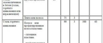
Table 2. Recommended cross-sections of steel (uncoated) electrodes for grounding installation.
Table 3. Recommended cross-sections of copper electrodes for grounding installation.
Table 4. Recommended cross-sections of galvanized steel electrodes for grounding installation.
In the form of electrodes, the following can be used for grounding:
- steel corner with nominal dimensions 50 x 50 x 5, having a cross-section of 480 - 500 mm2;
- a strip of steel with nominal dimensions 40 x 4, having a cross-section of 160 - 200 mm2.
Images of several types of electrodes that are recommended for use with various types of grounding. Selected vertical grounding materials are not completely dug into the ground. There should be 20-25 cm of electrode above the surface. At the next stage, the electrodes are welded to steel corners installed around the perimeter in the form of a triangle.
Connection diagram for steel angles welded together around the perimeter in the form of a triangle.
2.1. Natural grounding
2.1.1. It is recommended to use the structures listed in Table 1 as natural grounding conductors. 2.
Table 2. 
Explanations, requirements for use
Reinforced concrete foundations of buildings, including those with protective waterproofing coatings in non-aggressive and slightly aggressive environments
To connect the reinforcement of reinforced concrete columns with the reinforcement of the foundation, it is necessary to use a jumper with a diameter of at least 12 mm (Fig. 1).
The connection of metal columns with foundation reinforcement should be carried out according to Fig. 2.
The need to weld anchor bolts of steel columns (reinforcing bars of reinforced concrete columns) to reinforcing bars of reinforced concrete foundations is determined by the permissible current density in the reinforcement layer of concrete in accordance with the PEU
Reinforced concrete foundations of technological, cable, combined overpasses in non-aggressive and slightly aggressive soils in all climatic zones of the USSR
The metal connection of the reinforcement of reinforced concrete supports and foundations is not mandatory
Cable tunnels made of precast reinforced concrete, provided that embedded parts are installed in them, welded to the tunnel reinforcement, and the subsequent connection of the embedded parts with steel jumpers
Allowed to be used as additional natural grounding conductors if the resistance to spreading of reinforced concrete foundations of an industrial building or the touch voltage exceeds the standards established by the PEU
Rails of electrified railways at stations and hauls, as well as rails of access roads of AC traction substations
Grounding conductors must be connected to the rails only mechanically without welding (Fig. 3).
Crane track rails when installing a crane outdoors. Rail joints must be securely connected by welding, welding jumpers
The rails must be connected to an additional grounding conductor located near the crane
Well casing pipes
Grounding conductors of overhead power transmission line supports connected to the grounding device of the electrical installation using a line lightning protection cable, if the cable is not isolated from the line supports
Metal sheet piles of hydraulic structures, water conduits, gates, etc.
Grounding electrodes for repeated grounding of neutral conductors of overhead lines with voltage up to 1 kV in the case of using at least two overhead lines
Metal pipelines laid in the ground, except for sewerage and central heating pipelines. It is prohibited to use cast iron pipelines and temporary pipelines of construction sites as natural grounding conductors.
Lead sheathing of cables laid in the ground.
Aluminum cable sheaths are not allowed to be used as grounding conductors
Cable sheaths can serve as the only grounding conductors when there are at least two cables
Rice. 1. Connection of reinforcement of reinforced concrete structures: 1 – lightning protection mesh; 2 – down conductor; 3 – column reinforcement; 4 – grounding jumper; 5 – foundation reinforcement 
Rice. 2. Connection of a metal column with reinforced concrete foundation reinforcement: 1 – base reinforcement; 2 – foundation reinforcement; 3 – foundation; 4 – foundation bolts (at least two) connected to the foundation reinforcement; 5 – plates for welding grounding conductors; 6 – steel column 
* When connecting a metal column to reinforced concrete foundation reinforcement, the following must be taken into account: 
a) foundation bolts (at least two) must be connected to the column reinforcement by welding; 
b) the connection of the column reinforcement with the sole reinforcement must be made by welding; 
c) if the spatial frame of the column does not intersect with the reinforcing mesh of the foundation base, then it should be built up in two places using separate reinforcing bars and connected by welding to the reinforcing mesh; 
d) if the base of the foundation is not reinforced, then it is enough to weld the column reinforcement and foundation bolts; 
e) all frame rods of the foundation reinforcement must be connected to each other by welding; 
f) plates measuring 50x100 must have a thickness of more than 5 mm for welding grounding conductors. The distance from the plate to the finished floor level should be no more than 500 mm. The weld is made across the width of the plate on both sides. 
Rice. 3. Connecting protective grounding conductors to the traction rail: 1 – grounding wire; 2 – grounding clamp; 3 – hook bolt 
2.1.2. Natural grounding electrodes must be connected to the grounding mains by at least two conductors connected to the grounding electrode in different places. This requirement does not apply to overhead power line (OHT) supports, re-grounding of the neutral conductor and metal cable sheaths. 
2.1.3. In the case of using natural grounding electrodes (especially extended ones), when choosing places for connecting protective conductors to them, it is necessary to take into account the possibility of disconnecting the grounding electrode, for example, during repair work. 
Source
Grounding systems used in electrical engineering
Several grounding systems are used in electrical engineering - TN-C, TN-S, TN-CS, IT, TT. These designations are deciphered as follows:
۞ The first letter of the Latin alphabet determines how the power supply is grounded:
- T – the neutral conductor of the power source is connected to ground;
- I – any conductive parts are insulated from contact with ground.
۞ The second letter indicates the nature of grounding of exposed conductive parts of the electrical installation:
- T – exposed conductive parts are connected to the ground, regardless of the grounding of the power source;
- N - all exposed conductive elements are connected to the point at which the power source is grounded.
۞ the letters that are indicated in the designation after the letter N with a hyphen determine how the protective and working conductors are arranged:
- C – the functions of the protective and working conductors are performed by one common PEN;
- S – the functions of the protective PE and working N conductor are provided separately.
In the “Rules for Electrical Installations” these are the designations used.
TN-C system
The simplest and most “ancient” grounding scheme, in which the neutral and grounding conductors are combined. When a phase “breaks down” on conductive parts, the current goes into the ground, and the circuit breaker de-energizes the circuit.
However, this system has a significant drawback. Under heavy loads, the neutral wire may slowly “burn out”. In the event of a short circuit, which is formed when a phase “falls” onto the housing, the already damaged neutral can burn out so quickly that the machine does not have time to react - a shutdown current has not yet arisen in the circuit. As a result, the protective grounding will disappear along with the neutral, but the phase will remain on the housing, since the machine did not turn it off.
If a person touches conductive parts, his body forms a conductor between the phase and the ground. In this case, electric shock is inevitable.
TN-S system
This is a more modern system in which the neutral and ground conductors are separated throughout the circuit. This system is much more complex than TN-C, but it is also much safer. The third, grounded conductor in a single-phase network, or the fifth in a three-phase network, is connected to the ground loop at the transformer substation.
TN-CS system
The design of such electrical wiring involves combining a combined PEN wire and a separate grounding conductor. This happens, for example, if the wiring throughout the house is made with a separate grounding wire, which is connected to an independent grounding circuit, and the house is connected from the transformer substation using a combined PEN conductor.
This scheme turns out to be more economical compared to TN-S, since the longest section of the power line can be made without a separate grounding wire. However, this circuit is just as reliable as TN-S.
IT and TT systems
With the TT system, everything is very clear - the housing of the source (transformer substation) is grounded, and all electrical appliances in the house are separately grounded. This scheme is rare, but is found when installing electrical wiring in private homes.
The IT system is practically not found in everyday life. It is used in specific cases - for example, when supplying electricity to rooms with equipment sensitive to interference. The absence of grounding of the power source will minimize induced currents in the network. Safety is ensured by grounding each electrical appliance. This scheme is used in laboratories and hospitals.
ONLINE STORE
Product catalog | Installation | How to buy | Select grounding | Admin Panel | Grounding.Theory
| Sitemap | search | Lightning protection | Delivery | Guarantees | Geography GroundZ | Login | Cart | Alternative zz-6 | PHOTO | FORUM | Contacts | Some more information about grounding. | EXAMPLE ARTICLE of correct PE | GroundZ News | Basket Reactivator
In Russia, the main document regulating the requirements for grounding and its design is the RULES FOR ELECTRICAL INSTALLATIONS (PUE). At the moment, the seventh edition of the RULES FOR ELECTRICAL INSTALLATIONS is relevant. Approved by Order of the Ministry of Energy of Russia dated July 8, 2002 No. 204.
Grounding is an intentional electrical connection of any point in the network, electrical installation or equipment with a grounding device.
The grounding device (grounding) can be either one vertical electrode (for example, from a modular grounding) immersed in the ground to a certain depth (depending on the required resistance value), or it can be a set of vertical and horizontal grounding electrodes:
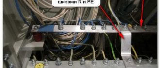
From the presented picture it is clear that the grounding device (GD) consists of a grounding conductor and a grounding conductor.
– a conductive part or a set of interconnected conductive parts that are in electrical contact with the ground. Or in simple words - part of the grounding device located in the ground - this can be steel angles, modular grounding in the form of copper-plated steel pins, heating pipes, well casing pipes.
What kind of lighting do you prefer?
Built-in Chandelier
Acceptable materials and forms of grounding conductors and grounding conductors in accordance with PUE 7:
The ground electrode can be a simple metal rod (steel or copper-plated) and/or a set of driven steel corners in the shape of a certain geometric figure (triangle, square, line, etc.)
Grounding electrodes are divided into artificial and natural.
– these are grounding conductors made specifically for the purpose of grounding people.
– these are metal objects in contact with the ground that can be used for grounding purposes: water pipes, well casings, etc. The use of natural ground electrodes is also regulated by the Rules for the Operation of Electrical Installations (PUE ed. 7).
– a conductor connecting the grounded part to the ground electrode. These can be steel plates, galvanized steel plates, copper cables with a cross-section in accordance with regulatory documents.
Below are the points of the PUE edition 7 that normalize the cross-sectional area of protective conductors depending on the cross-sectional area of phase conductors and some features:
Clauses of the PUE edition 7 regulating the resistance of grounding devices:
GOST R 50571.2-94 “Electrical installations of buildings. Part 3. Basic characteristics" regulates the following grounding systems: TN - C ,
TN - S , TN - C - S , TT , IT .
Grounding of electrical installations and equipment | rules and requirements
The main requirement for groundings up to 1000 Volts is their ability to create a reliable chain for emergency current charges to flow into the ground. It is estimated by the amount of resistance that ground fault currents have to overcome.
Expert opinion
Viktor Pavlovich Strebizh, lighting and electrical expert
Any questions ask me, I will help!
This is explained by the fact that, when the insulation breaks down, the main part of the current charge flows along the grounding bus into the protective circuit, the resistance of which is an order of magnitude lower than the same indicator for the human body. If there is something you don’t understand, write to me!
Natural and artificial types of grounding
Natural grounding - structures in direct contact with the ground. The following are used as natural protection:
- Lead sheathed cables laid in trenches underground; rail tracks of non-electrified access roads, railways, etc.
- Reinforced concrete and metal structures of any building structures that are in direct contact with the ground.
- Underground water and sewer lines. Do not use metal pipes that carry explosive or flammable substances.
Artificial grounding As a rule, horizontal and vertical electrodes are used for artificial grounding. The role of vertical can be played by a twig or steel pipe, at least 3 meters long. The essence of the implementation is to immerse the upper ends into the ground and connect them with a strip of steel using a welding machine. This technology forms a grounding loop.
For safe use of electrical appliances, natural grounding conductors must be used. Their use allows you to save the family budget and time, since there is no need to construct artificial grounding conductors. If the natural type satisfies all the requirements of the PUE for resistance to spreading, the artificial one need not be built.
Comparison of artificial and natural contour
Pipelines located in the ground act as a natural grounding system. A natural circuit is two or more metal structures that are in contact with the soil for the safe use of household appliances. Natural grounding is also divided into the following types:
- Pipelines intended for various purposes located in the ground.
- Reinforcement of building structures, which is immersed in soil layers.
These types of protective contour must be associated with the object by at least two elements. As a rule, they are installed in different parts of the structure.
As a natural defense, it is prohibited to use:
- heating systems and sewer lines;
- pipes whose surface is coated with an anti-corrosion compound;
Artificial ground electrode - metal structures intended for transportation of flammable and toxic substances.
An artificial contour is a special structure made of metal. To work, they are immersed in layers of soil. The most common examples of artificial protective contours are:
- Metal sheets laid in the ground. They can have different shapes and sizes.
- Rods, angles, pipes and steel beams placed in the ground.
Which grounding device is more effective: natural or artificial?
All news
02.03.16 ,
There are two types of grounding: artificial and natural. The role of natural grounding is performed by parts of the metal structures of the object that are constantly located in the ground: foundation reinforcement, water supply, casing pipes, etc. Artificial grounding is a separate independent structure mounted in the ground. Almost every contractor is faced with the question when installing grounding, which grounding is better: artificial or natural?
To answer this question, let us turn to regulatory documents, namely paragraphs 1.7.54 and 1.7.109 of the “Rules for the Construction of Electrical Installations” (PUE). Here we see the answer: both natural and artificial grounding electrodes are suitable for grounding. Let's find out in what cases it is more correct to use one method or another? Let's look at each option in more detail.
Option 1. Natural grounding
If you decide to use a natural grounding system, then you need to know about many factors: the type of foundation of the object, its material, as well as the aggressiveness of the soil. Section PUE 1.7.109 outlines design options for the facility that can be used as a grounding conductor. The most common of these is the foundation. There are several types of foundations: strip, columnar, pile and slab. The choice of base depends on soil density, seismic activity, surface topography, groundwater level and soil freezing depth. The materials used are: reinforcement, concrete, brick, wood, rubble, asbestos-cement or metal pipes. Detailed information about the foundation can be found in the regulatory documentation (SNB 5.01.01-99 Foundations and foundations of buildings and structures). Thus, when deciding to use your foundation as a ground electrode, you need to make sure that it has electrically connected metal parts.
All elements of the natural grounding system must be combined into a common circuit and in contact with the ground to drain currents directly or through concrete. Also, the selected ground electrode must meet the requirements of the PUE regarding the cross-sectional area of the conductor (Table 1.7.4). During the operation of a natural ground electrode, destruction of its structure or disruption of the operation of devices associated with it must not be allowed.
Sewage and central heating pipes, as well as pipelines for flammable and explosive mixtures, are not allowed as a grounding conductor. Pipes easily corrode the metal, breaking the electrical contact. This type of grounding is certainly more economical: it does not require costs for materials, installation and dismantling of the grounding device, but during its long-term operation, repairing damaged areas will cost no less than installing a separate grounding.
Natural grounding
Option 2. Artificial ground electrode
It is a set of electrodes installed in the ground and connected to electrical equipment using a grounding conductor. Copper-plated steel, galvanized steel or ferrous metals are used as electrode materials:
- Copper-bonded steel has the highest electrical conductivity and adhesion to various materials. The bond between copper and steel is stronger than with zinc, which is why copper-plated rods are stronger than galvanized rods. Copper is less electrochemically active than zinc and steel, which increases service life up to 100 years.
- Galvanized steel is a corrosion-resistant material with low resistivity. Electrodes made of this metal are highly resistant to acidic environments with an average service life of 30 years.
- Ferrous metals have high mechanical strength, but quickly break down when used in an aggressive soil environment, forming rust and corrosion. And, as a result, we get a high current flow resistance, which poses a danger to human life.
The dimensions of the conductors must comply with the requirements of GOST R 50571.5.54-2013. Many options for installing a grounding device help to ensure the required contact area of the surface of the ground electrode with the ground, which in turn allows you to influence the value of the resistance to current spreading. The advantage of an artificial ground electrode is that it can be installed deep into the ground, where the resistivity is lower due to groundwater that flows down. This ensures the stability of the final resistance.
Artificial ground electrode
Let's summarize: you can choose any of the options described above as a grounding conductor, the main thing is to approach this issue responsibly.
For the safety of your home and long service life, choose a grounding device with a corrosion-resistant coating manufactured in accordance with regulatory guidelines. Call or write to our Technical Center and we will select the necessary grounding kit for your facility. See also :
- Grounding in a private house
- What can be used as a natural grounding agent?
- Lightning protection for a private home and bathhouse
[News block code for embedding on your website] [RSS feed for subscribing to news]
Do you want to receive selected news about lightning protection and grounding once every 3-4 weeks? Register and automatically receive an email newsletter with a selection.
All news is published in our groups in instant messengers and on social networks. [News channel on Telegram]
See also:
Video recording of the webinar “When is isolated lightning protection useful?”
Airplane grounding project
Grounding of a diesel generator set and a fire station in the Krasnoyarsk Territory
Features of grounding design on an electrified railway
Why do airplanes need grounding?
The partner appreciated the high quality of ZANDZ products
Webinar "Online calculation of lightning protection of an explosives warehouse"
How does lightning protection work for wind generators?
“Manual” for measuring the resistance of a grounding device
Webinar “Dangerous contradictions in the scientific and technical documentation for lightning protection of explosive objects”
Why do you need a ZANDZ modular grounding starting lug?
Grounding device technologies
There are several ways to make a ground loop.
Most often, two of them are used:
- Modular-pin grounding.
- Traditional grounding.
Modular grounding design
For its construction, rods made of high-quality copper-coated metal are used. They are driven vertically into the ground to a depth of about 1 m, the diameter of the rods is 14 mm. 30 mm threads are cut along the edges of the rod and also coated with copper.
The metal parts of the structure are connected together with brass couplings. They are connected horizontally with steel strips with brass clamps or a set of copper wire is used for this. Also, a connection is made between the grounding loop and the distribution panel. To protect grounding elements from corrosion, the kit includes protective paste.
Traditional grounding
Such a system is made from ferrous metal: strips, pipes, corners. Three metal electrodes are driven in a triangle 3 m into the ground, with an interval of 5 m. Next, the electrodes are connected into a common circuit using a metal strip and electric welding.
Such grounding has several negative properties (for example, the complexity of creating a circuit and corrosion, which destroys the metal of the product), for this reason, in our time, they are trying to use a more advanced method of grounding instead.
Natural grounding elements
Most often, they are used for grounding electrical equipment. Metal elements of various reinforced concrete structures are used as natural grounding conductors, for example, the foundations of substations and power lines and the foundations of buildings.
Additionally, for natural grounding, parts of underground communications made of metal are connected, for example, cable armor and all kinds of pipelines are suitable, sometimes it is permissible to connect ground communications, for example, rail tracks are suitable for this purpose.
Other options
There are other natural grounding agents. To explore suitable options, you can use the PUE clause 109 of section 1.7. It states that using a steel pipeline is quite suitable. The main condition is the presence of non-flammable liquid inside the pipeline. In addition, a metal well casing can be used as a natural grounding conductor.
For power lines, reinforced concrete footrests are used as grounding conductors, since they are well moistened upon contact with the ground.
Thus, using natural grounding conductors can significantly save time and money, but it is necessary to take into account a large number of factors that can affect safety. The structures must not only form a single circuit, but also provide resistance not exceeding the permissible parameter.
TN systems
Such designs are distinguished by the presence of a solidly grounded neutral and the connection to it of all network elements capable of conducting electricity.
The connection to the neutral is made using neutral conductors.
Electrical cabinets, panels and instrument housings are connected to the PEN conductor. This is done to create a short circuit when the wiring is pierced into the housing, as a result of which the circuit breakers de-energize the network going to the failed section of the network, thus preventing electric shock to people nearby.
System with zero and dissected working conductor
TN-S system
The TN-S system for safety is equipped with two, rather than one, neutral wire, one of them serves as a protective wire, and the second is used as a neutral conductor connected to a solidly grounded neutral. This design is the safest today, capable of effectively protecting against electrical shock.
The operating principle of this design is that only one phase is used to supply the operating voltage and zero.
The wiring is made with a wire of three cores, one of which serves as a zero and is connected to the input wire.