Safety inspectors always pay attention to the arrangement of the so-called re-grounding
The issues of organizing a grounding loop on the consumer side are always given increased attention, since the health of power grid users ultimately depends on the correctness of its arrangement.
According to the requirements of regulatory documents (PUE, in particular), a grounding loop that protects people working on electrical equipment is mandatory under any circumstances. This is explained by the fact that the grounding function installed at the transformer substation, transmitted via a separate protective wire, is very unreliable due to the high probability of a break in the neutral wire (“burning out” of the zero).
Why is re-grounding necessary?
From a technical point of view, re-grounding (RE) is a protective device specially installed on the consumer side that guarantees the safety of people working on the line. It “triggers” in the event of loss of communication with the substation via the neutral or combined wire.
Scheme of re-grounding operation in the event of a zero break on a 0.4 kV overhead line
To arrange re-grounding, it is allowed to use so-called “natural” grounding electrodes, which include:
- metal frames of structures already laid in the soil and having direct contact with it;
- metal protective casings and armor of power cables buried in the ground;
- sections of steel pipes (with the exception of gas mains and oil pipelines);
- railway rails.
Please note: Using ready-made structures already laid in the soil as a re-grounding loop simplifies the installation of the charger and allows you to minimize the costs of its arrangement.
Note that their resistance is not controlled by the user in any way, so its value can change unpredictably at any time. To eliminate this situation, in especially critical cases, artificial grounding structures are installed that have stable technical characteristics.
Re-grounding the neutral wire is one of the ways to organize an artificial system that can duplicate the function of a station switchgear. The last explanation exhausts the question of what re-grounding and how it can be arranged.
Application of re-grounding in a classic TN system
Re-grounding is a critical element of a comprehensive electric shock protection system. It is used for grounding the neutral protective conductor of PE and PEN electrical networks up to 1000 Volts in a TN system with a solidly grounded transformer neutral.
Classical grounding systems are usually distinguished by the state of their neutral, which can be solidly grounded or isolated. In accordance with this feature, they are divided into two large groups and are designated by the appropriate combination of English letters. “T” stands for ground and “N” stands for neutral, which when written together symbolizes a grounded “zero.” In addition, these systems provide conductors and busbars, designated as PE (separate grounded connection) or PEN - combined working and protective busbar.
Depending on the chosen scheme, the permanently grounded neutral wire N can be either independent from the protective PE conductor, or can be connected to it, forming a PEN bus. In the first case, we get the TN-S system (“Separate” or separate gasket), and in the second - TN-C.
Please note: Here "C" stands for "Combined" or combined.
There is another option when two wires (protective and neutral) are combined on the substation side, and when entering the facility they are divided into a protective conductor PE and a functional bus N. This organization of the consumer protection system is called TN-CS and also requires the grounding of the neutral wire .
Grounding of 0.4 kV overhead line supports: device
As support structures for overhead power lines, two types of poles are used, which have excellent design features, and which are grounded in accordance with the rules of the Electrical Installation Code.
Types of supports:
- Wooden;
- Reinforced concrete.
Wooden structure, assembled from two round logs (without bark). The dimensions of the logs vary from: length 5 – 13 meters, width 12 – 26 cm. To ensure the longevity of this structure, wooden supports are coated with a special antiseptic composition. Wooden posts are divided into two types (C 1 and C 2).
Reinforced concrete pillars are made in the form of rectangular or trapezoidal structures. These supports are designated by special markings in the form (SV). After the letter designation, numbers are written indicating the size of the pillar.
For example, CB 95 means that the reinforced concrete pillar is 9.5 meters long. There are several types of supports, marked SV.
Note! Grounding (re-grounding) of the neutral wire is carried out by welding to the metal parts of the reinforcement pole.
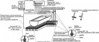
The conductors are connected as follows. Neutral conductors (working and protective) are connected at the top of the reinforced concrete structure. It is worth noting that to ensure correct connection, provided that the structure is equipped with a braced post, it is necessary to connect the conductors to it.
The connection to the power line pole is made according to a special diagram using various fasteners.
To carry out repeated grounding on a wooden pole, you need to install a metal wire ground electrode. This wire is attached to a ground electrode, which is driven into the ground. For wires larger than 6 mm, a galvanized grounding conductor is selected; for wires less than 6 mm, a metal grounding conductor is selected.
Application of the TN-C system
The TN-C system was widely used in previously common two-wire networks, which are often found today (mainly in older buildings). From the point of view of the average user, it is characterized by the fact that in this case there is no special grounding contact in the sockets.
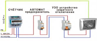
TN-C grounding system
In networks designed based on this scheme, the neutral wire is grounded only on the station side (photo above). Therefore, if it accidentally breaks or the so-called “burnout”, all electrical installations and devices connected to the line are completely unprotected. This forces users to personally ground each unit of household appliance used in the house or install an RCD.
Please note: For owners of private and country houses, the conditions in this case are more than favorable, since they can organize re-grounding by installing an external circuit directly on the site.
This system has not been used in modern construction for many years; today it has been replaced by the more efficient TN-S.
Application of the TN-S system
The TN-S system is more advanced in terms of organizing protection, that is, it has a greater degree of electrical safety. This is explained by the fact that it has an “independent” grounded conductor that serves exclusively for these purposes. However, due to the use of additional copper material, the cost of the system has increased significantly. In the case of three-phase power, for example, from a power source (transformer substation), it is necessary to lay a cable containing five wires. These are the three required phases A, B and C, as well as the neutral and protective conductor PE.
Grounding system TN-S
When implementing the TN-C system in electrical circuits, the organization of re-grounding of the neutral wire is also mandatory. It is produced by connecting the neutral conductor to the earth conductor of the protective circuit, installed on the consumer side.
TN-CS system
This scheme was developed to eliminate the shortcomings of the TN-S system and provides for the use of a combined PEN conductor as a common bus, laid only before entering the facility.
Important! Immediately before entering the building, the common bus is divided into two cores (neutral N and protective conductor PE).
This system is a cross between the two protection options already discussed. It is not without the same disadvantages as TN-S, since if the PEN conductor on the line from the substation to the facility is damaged, all electrical appliances installed in it will be under dangerous voltage. For this case, the PUE requires additional protection of the PEN tire from deformation and mechanical damage.
Grounding system TN-CS
In this system, the equipped ground loop is the reconnection of the neutral wire PEN with the charger before entering it into a specific object. In the event of an accidental break of a conductor in the section of the power line “substation transformer - building”, grounding is carried out exclusively through a PE wire.
To do this, at the input to an electrical installation with a voltage of up to 1 kV or in the distribution cabinet at home, the PEN wire must be “split” into two busbars. One of them is used as a working neutral conductor, and the second as a grounding conductor.
The considered approach to the organization of power protection makes it possible to exclude the introduction of induced currents into the power circuits of the house through the effect exerted by the e/m fields of external communications. In addition to this, it reduces the potential on the housings of equipment and household appliances in the event of an accidental break of the N-conductor.
Overhead power lines
On power line (VL) supports, in accordance with the current provisions of the PUE, re-grounding of the PEN conductor laid from the transformer substation is mandatory. This can be explained by the need to increase the electrical safety of personnel working on overhead lines, as well as the creation of conditions for reliable operation of circuit breakers.
Scheme for re-grounding the neutral wire in the power supply system
Please note: The number and frequency of placement of repeated grounding conductors along the route of power transmission lines is determined by the power supply project prepared for it.
PZ must be established in the following places:
- On supports located at the end of the overhead line.
- On poles, immediately before introducing the “air” onto the object.
- Before any branch from the highway, the length of which is more than 200 meters.
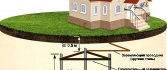
Grounding an overhead line support
To install a grounding device, the underground part of an overhead line support is usually used. If it is not enough to obtain the required characteristics, an additional circuit is made. To design the descent from the top of the pillar, wire without insulation with a diameter of 6.0 or 8.0 mm is used. In addition to the PEN wire, all elements of the support structure made of metal must be grounded. According to the requirements of the PUE, the resistance of the repeat circuit should not exceed 30 Ohms.
On poles with street lighting devices, not only SIP wires are subject to mandatory grounding, but also lamp housings and other metal-based parts of the poles themselves. For these purposes, in urban areas with limited deepening capabilities, horizontal stripes are often used instead of typical vertical pins. After their installation, it is necessary to test the equipped system, checking the real resistance of the grounding device using special measuring tools. Without re-grounding the self-supporting wires and city lighting poles, this section of the route is not allowed for operation by the selection committee.
Types of supports
Wooden
Wooden supports are currently used to a limited extent, mainly in sparsely populated areas. They have such advantages as low manufacturing cost and ease of installation, light weight, and high load resistance. In addition, wood is a good dielectric, which increases operational safety. The disadvantages of wooden supports include the need to select logs for one overhead line with the same diameters to ensure equal load distribution, high susceptibility to mechanical damage and rapid wear of the wood during operation. To eliminate the negative influence of the environment and reduce rotting processes, wooden supports are impregnated or coated with special compounds.
The supports are made from coniferous wood. The diameter of the logs and length are selected according to the class of support. The classification of supports is designed in such a way that a log of a certain diameter at the upper end and a certain length must have the corresponding weight or volume. Wooden supports can be classified as L, M or S class
Supports for overhead lines up to 1 kV must have a diameter of at least 14 cm. The height of the supports is from 6 to 13 meters. Depending on the class of wood and its cubic capacity, supports can weigh from 180 to 350 kg.
Reinforced concrete
Reinforced concrete supports are stronger and more stable than wooden ones. Their wear life is significantly longer than that of wooden supports, which is why they are most widespread in the construction of overhead lines of different voltage levels.
Reinforced concrete supports are made from reinforced concrete; before manufacturing, they are calculated depending on what role the support will play in the overhead line. Requirements for load distribution are established by GOST and PUE.
Reinforced concrete supports are classified in the following order:
- special - designed for certain conditions: climatic conditions, when crossing obstacles, when crossing overhead lines and others;
- end - installed at the end of the overhead line;
- corner - used for overhead line turns;
- anchor - tension the wires in straight sections;
- intermediate - support, but do not tension the wires.
Reinforced concrete supports are used in all overhead lines - both with conventional wires and with SIP.
The photo below shows the appearance of a reinforced concrete support.
The following reinforced concrete structures are used:
- CB 105;
- CB 110;
- CB 95;
- CB 85.
In order to carry out secondary grounding of the PEN conductor, reinforcement is welded on both sides of the support. This is done to fulfill the requirements of the PUE (clause 2.4.40, see Chapter 2.4): “The PEN conductor should be connected to the reinforcement of reinforced concrete racks and struts.”