Good day to all! Anyone who has ever come across any network or computer equipment has seen names and designations such as “LAN” connector or RJ45 connector. Immediately questions arise in my head - what is it and why is it needed? In this article I will try to analyze this issue in as much detail and as clear as possible for the average user. It may also be useful for specialists to learn something new from this article.
HELP! If you have any questions or notice an error, please write in the comments immediately.
What is rj45 connector and RJ45 connector
Registered Jack (RJ) is a standardized physical network interface necessary for connecting telecommunications or information equipment.
It is important to note that the concepts of connector and connector are often not distinguished in the literature. This happens because in the English documentation all such interfaces are called connector.
In our country, according to SCS standards, the concepts of connector and connector are distinguished.
- A connector is an element for connecting and connecting line cables.
- A detachable connection consists of a plug connector (plug, plug) and a female connector (socket).
- Unlike a connector, a connector is a part of a connector that is used to connect individual cable conductors in a connector. Formally, a connector is a gold-plated contact with a “knife” for inserting into a cable core.
Letters and numbers RJ45 is a standard for an unbalanced connector between female and male connectors. A rj45 plug connection is formed by inserting a plug into a socket.
Please note that each connector has two connectors (pins). One mortise connector is used to connect twisted pair wires. The second connector is contact; it switches the connection in the compatible connector.
“Lazy crimp” 2 pairs
Oddly enough, this twisted pair pinout is used very often, since it is quite simple. If you have already tried to crimp all 8 wires at least once, then you have most likely encountered some problems when the wires are bent, do not fall into the desired groove, and as a result you have to start all over again. This scheme is used only when connecting devices and network equipment that do not need to use speeds above 100 Mbit per second.
Let me remind you that when crimping 4 pairs, a network cable can transmit data at a speed of 1000 Mbit per second. If you use only 2 pairs, then the speed drops to 100. Of course, in most cases this speed is enough, but I strongly do not recommend using it.
4 wire crimp standard
The fact is that the speed and flow of information exchange in organizations is beginning to increase. Consequently, at some point this pinout will not be enough. Then the boss will force you to go and re-crimp all the cables to the usual standard circuit. You will end up doing double or even extra work. That is why, if you have a standard 8-core cable, then we use a twisted pair connection according to the diagram from the last chapter.
The same goes for home. Imagine that you exchanged your old 100 Mbps router for a new one that supports 1 Gbps. If you previously had a different pinout for 2 pairs, then you will need to re-crimp everything. In the worst case, you will need to change the 4-core cable to an 8-core one.
NOTE! The RJ-45 connector differs between 100 Mbit/s and 1000 Mbit/s in the same way. The first has 4 cores, and the second has all 8.
RJ45 or 8P8C connector
If you've dealt with computer networks before, you've no doubt heard that both the terms RJ45 and 8P8C are used interchangeably. However, let's find out why such a contrast arose in the first place.
History of the RJ45 connector
Let's start with the RJ45 connector. This term is now most widely used to refer to Ethernet cable connections.
RJ is translated and stands for “registered jack”. The RJ connector was originally developed as part of a standardized telecommunications network interface for connection in telephone networks.
RJ connectors were developed as a significantly smaller and cheaper replacement for older telephone methods of installing wire cords or bulky plugs.
With the advent of computer networks, a new but very similar connector was developed for data transmission: 8P8C.
Connector 8P8C
In the 8P8C (8Position8Contact) connector, each plug has eight holes for wires, which are spaced approximately 1 mm apart. The individual cores of the twisted pair cable are inserted into these holes to connect to the connector.
In the RJ45 Ethernet connector, the inserted wires are crimped. There are 8P8C connectors where the contact of the cores is carried out differently.
Due to its popularity and maximum distribution, the RJ45 connector has become the formal designation for any eight-position/pin 8P8C modular connector used in computer networks (Ethernet). Therefore, this plug is often called the rj45 8p8c connector.
The formal differences between 8P8C and RJ45 connectors are shown in the following diagram:
As you can see in the photo, these connectors are not fully compatible with each other. 8P8C connectors can be connected to RJ45 sockets, but the reverse is (formally) not possible.
So what the industry calls RJ45 connectors are actually 8P8C modular connectors. They are sold as rj45 8p8c connector.
Today, almost all electronic equipment using 8P8C connectors will use the term RJ45 in their documentation, which is technically incorrect, but everyone understands. This misuse of terminology is widespread in the industry and is unlikely to change anytime soon.
There's really no reason to worry. However, when purchasing a connector, look for the formally correct marking “RJ45 (8P8C)” to avoid confusion or disputes.
Origins of RJ45
Let's start with RJ45, perhaps the most widely used term for Ethernet cables today. RJ stands for Registered Jack, and the RJ45 connector was originally developed as part of a standardized telecommunications network interface for the purpose of interconnecting telephone networks. RJ platform connectors were designed as smaller, cheaper replacements for older methods of telephone installation of wire cords or bulky plugs.
With the advent of computer networks, a new but very similar connector was developed for data transmission: 8P8C.
Two connection diagrams T568A and T568B
There are two RJ45 pinouts, T568A and T568B. They also work if you see 8P8C connectors in the documentation.
As you know, the colors of the wire pairs of a twisted pair cable are different. Pin pins T568A and T568B define the location of eight individual wires in the connector. Each of these wiring patterns has its own color scheme, and color matching is important to ensure electrical compatibility.
Over time, the T568B circuit became more popular. The differences in color designations are shown in the table below.
Specifications
The RJ45 connecting element consists of a plug (transparent impact-resistant plastic) equipped with a latch, which ensures reliable fixation of the cable in the port of the system device, network interface card. The technical characteristics of connectors depend on their type.
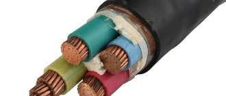
- The RJ45 connector has 8 sockets for conductors, as well as 8 knives. The pads receive the signal from the twisted pair. The knives ensure reliable fastening of the cable in the clip. Knife-contacts are made in a straight version (for stacked wires) or with indentations - for connecting single-core wires.
- The contact pads and knives are coated with gold plating. The quality and speed of signal transmission depends on the thickness of the coating.
- Shielded (foil wrapped) connectors (STP) are only suitable for cable with a protective shield. Used in connections with shielded equipment. Unshielded plugs are used for ordinary (UTP) wires.
- Categories – 5 (signal transmission speed 100 Mbit/s), 5e (over four pairs up to 1,000 Mbit/s), 6e (Fast or Gigabit Ethernet type networks, about 10 Gbit/s).
- Internal connectors are built into a mounting box that is recessed into the walls. External connectors are designed for free external connection.
- Coaxial plugs are used when connecting coaxial cables, optical plugs are used in fiber-optic networks.
Sockets with built-in connectors are distinguished by the number of connectors - single, double, terminal (from 4 to 9 pieces). Additionally, they can be equipped with HDMI or USB ports.
Types of RJ45 connectors
To talk about the types and types of RJ45 connectors, let's talk about connecting the wire (cable core) to the connector.
This type of detachable connection does not require preliminary stripping of the cable cores from insulation. The cores are inserted into the holes of the connector and connected to the contact by cutting the IDC knives of the connector into the core while crimping it.
Depending on the type of knives used, the connectors are divided into:
- For connectors for single-core cables;
- For multi-core cables;
- And universal.
Shielding
RJ45 connectors are distinguished by the presence of a protective shield against interference. If there is one (photo above), the abbreviations FTP and STP can be found in the designation, similar to the marking of TP wires.
Connector category RJ45
Just like linear cables, the connectors for their switching have categories. RJ45 connectors have categories 5e or 6. The connector category is selected according to the category of the cable used or according to the design documentation.
Advantages and disadvantages over other connectors
RJ45 connectors are universal in use. This is facilitated by a significant number of advantages of this type of connectors:
- Standardization of production made it possible to unify products. They are available for purchase.
- Easy installation of clips - you can do it yourself.
- The connector body is made of high-strength plastic, ensuring high wear resistance of the products.
- The low price of connectors is ensured by their mass production.
Among the individual disadvantages of the connector, one can highlight its one-time use. Dismantling of the cable is carried out only by cutting. The clip cannot be reused.
Cable connection methods
The RJ-45 data transmission cable consists of four pairs of wires. They differ in color (solid color, with a white stripe). There are two layout methods for the RJ-45 connector: T-568A or T-568B. 10BaseT (100BaseT) Ethernet networks use only two pairs of colors - green and orange. Brown and blue can be used to create another Internet line, as well as connect a telephone or fax.
To make a secure connection between the cable and the connector, all eight wires must be positioned correctly. Pinout is performed in two ways - A or B.
T-568B standard:
- White-orange;
- Orange;
- White-green;
- Blue;
- White-blue;
- Green;
- White-brown;
- Brown.
Standard T-568A:
- White-green;
- Green;
- White-orange;
- Blue;
- White-blue;
- Orange;
- White-brown;
- Brown.
The cable is installed using the direct method - one standard at both ends (T-568A or T-568B). The cross method is also used - one end is connected according to the T-568A circuit, the other - according to the T-568B circuit.
Pinout diagrams
The twisted pair pinout assumes two types of connection:
- T568A standard;
- T568B standard.
For ease of understanding, you need to remember the following pinout color scheme: the first standard assumes white-orange and orange, the second - white-green and green.
The second RJ45 crimping scheme is more popular, however, when forming an internal network, crimping can be performed using any of the above methods.