Many homeowners have to replace or install light switches. The most commonly used connection diagram is a single-key switch - one of the simplest schemes for turning on lamps or lamps. This article describes step by step how such a scheme is assembled.
Before starting any work related to electricity, the first thing you need to do is de-energize the electrical wiring - turn off the input circuit breaker, and also take measures to ensure that no one accidentally turns it on.
This is especially important if the electrical panel is located on a landing in a multi-story building or on the street.
To install and connect the switch you will need:
- – the switch itself;
- – distribution box;
- – connecting wires;
- – insulating PVC tape.
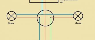
Connection diagram for a switch in a distribution box
Connecting a wire directly to a light fixture or switch is quite simple - it doesn't require any explanation.
This article will discuss how to connect wires from a lamp, electrical panel and switch in one junction box.
Once again we would like to remind you that all work on connecting wires in the distribution box, connecting switches and lamps should begin only after the mains voltage has been removed.
| The switch connection diagram is quite simple, but one rule must not be forgotten: the phase wire is connected to the lamp through a switch, that is, the phase must always be connected open-circuit. |
By following this simple rule, when the switch breaks exactly the phase and not the zero, you will ensure your safety and also make it safe to operate electrical equipment in your apartment.
If the switch disconnects from the load not the phase, but the neutral wire, then the wiring will always remain energized, which is not only inconvenient, but also dangerous.
For example, you need to replace a light bulb that has burned out in a chandelier. If the switch turns off the neutral wire and not the phase, if you accidentally touch the current-carrying parts of the chandelier or the base of the light bulb, you may get an electric shock, since these parts are under phase voltage.
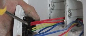
You can determine the phase wire in the distribution wiring using an indicator screwdriver.
Again, for safety reasons, the phase wire (usually red) must be connected to the lamp socket in such a way that the light bulb is connected to the phase by the central contact of the base.
This reduces the likelihood that a person will touch the phase wire.
The switch connection diagram consists of one or more light bulbs connected in parallel, a single-key switch, a distribution box and a 220-volt power source.
Specialized stores offer a wide range of wires for electrical wiring, so for phase and zero it is better to take wires of different colors, for example, red and blue.
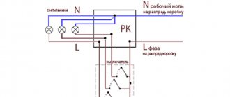
So, a two-wire cable runs from the distribution board to the distribution box. It is very convenient if it is two-colored, for example, the phase wire is red and the neutral wire is blue.
In addition, a cable from the lamp and a cable from the switch are suitable for the junction box. The phase wire from the distribution board (red) is connected to the red wire going to the switch.
The second (blue) wire from the switch is connected to the red wire, which is connected to the load (lamp, chandelier). As a result, we made the phase that goes to the lamp commutated.
The neutral wire (blue) from the electrical panel is connected to the neutral wire, which goes to the load (light bulb).
The result is that the neutral wire from the junction box goes directly to the light bulb, and the phase is connected to the light bulb through a switch.
The scheme works as follows. When you press the switch key, the circuit is closed, and the phase from the electrical panel is supplied to the lamp, its light bulb begins to shine. By pressing the key again, the electrical circuit is broken and the light bulb turns off.
After all connections, the twisting points are thoroughly insulated and neatly laid. It is best to connect the wires in the junction box by twisting and soldering.
Connection diagram for socket and switch in one junction box
Very often, a distribution box is installed in each room of the apartment, where all the switches, lamps and sockets of this room are connected.
In this case, due to the large number of wires going to the junction box, it is quite difficult to figure out what needs to be connected where.
How to connect a socket and switch to a distribution box?
Let's consider the option when a socket and a lamp are simultaneously connected to one distribution box.
So, two wires come from the distribution board to the box - red (phase) and zero (blue).
The procedure for connecting the switch and lamp is exactly the same as discussed above.
The socket is connected parallel to the supply wires: the socket phase is connected to the supply phase (both wires are red), and the zero from the socket is connected to the neutral supply wire (both wires are blue).
The connected wires must be well crimped and soldered, after which they are securely insulated and neatly placed in the box.
Any modern room needs to be equipped with basic electrical contactors for connecting electrical equipment and lighting. Let's look at how to connect a socket, a switch with wiring and a light bulb, as well as the basic circuit, the most common options and their features.
Connecting a lamp with a two-key switch
- Phase, the function of which is to power the serviced outlet, carrying electric current to it. This is the only wire whose insulation color is not regulated by the rules: the main thing is that it differs from the colors of the other two cables.
- Neutral wire with a blue or light blue sheath. Like the phase, it is connected to the power contacts of the socket in the distribution box.
- Grounding, whose role is to protect residents from electric shock when touching the body of an electrical appliance, as well as to prevent short circuit situations. Its insulating material is yellow or green. The wiring is connected to special socket contacts designated for grounding.
Useful tips Connection diagrams Principles of operation of devices Main concepts Meters from Energomer Precautions Incandescent lamps Video instructions for the master Testing with a multimeter
Connection diagram for a lamp when combining a socket and a switch in one unit
A socket and a switch combined in one housing are far from uncommon. Today factories produce them in large quantities. Their main advantages are saving wires and space, lower labor and time costs and high operational safety. To connect the device to a light bulb, you must perform the following steps:
- Prepare a place on the wall surface for a socket box. Modern houses made of reinforced concrete elements already have mounting holes with wiring. If they are not there, you need to use a hammer drill. In wooden houses, overhead structures with external wiring are often used.
- A two-core wire is laid from the main electrical panel to the distribution box. Phase and zero will follow it.
- You also need to connect the para-core conductor from the light bulb and three wires from the block with the switch and socket to the distribution housing.
- The current source in the panel is connected with wires: the phase is sent to the socket and switch.
- The neutral conductors of the light bulb and socket must be connected to a similar wire of the general electrical network.
- The remaining two wires (coming from the chandelier socket and the switch) are combined and isolated.
- If there is a ground conductor in the housing of the socket switch, it is necessary to connect it to the ground conductor.
Read also: Dip 300 lathe controls
This connection diagram will allow you to use devices combined into one module independently of each other. However, there is another technique - when current is supplied to the outlet in the switched position and vice versa. With this option, the algorithm of actions is as follows:
- The installation site is being prepared (according to the diagram above).
- Three two-wire conductors are supplied to the distribution box - in pairs (phase + zero) from the socket, switch and panel.
- The phase conductor of the common network must be connected to a similar wire of the switch.
- The zero branch is twisted with the wire from the outlet
- The two remaining free conductors in the device are connected to each other.
Important! The given connection diagram for an socket switched by means of a switch is suitable for rare use. For example, it can be used to turn on and off a light bulb in a basement powered by an extension cord with a plug.
Varieties
- An indoor unit consisting of a switch and a socket without grounding. This is the simplest and cheapest model. However, with modern household appliances, the lack of grounding is a disadvantage.
- Indoor unit with switch and socket with grounding. The switch key may have a special light indication, which will help you easily find the switching device in the dark.
- An outdoor unit with a single-key switch and a socket equipped with a special plastic cover and having a degree of protection IP 54 (against dust and water).
Exactly the same models can be made using a triple or double switch.
external waterproof switch-socket block
Based on the location of the switch and socket themselves, the blocks are divided into horizontal (switching devices are located nearby) and vertical (the switch is located on top of the socket).
vertical block with illuminated switch
Outdoor units are used for installation with open electrical wiring, when the switch and socket are not recessed into a special hole, but are fixed with a strip on the wall surface. In this case, the wires are laid along the walls; they can be laid in special plastic boxes, inserted into corrugated pipes, or simply openly attached to the walls using porcelain insulators.
Indoor units are used for hidden wiring. The device itself is inserted into a socket box located in a wall mounting box, and the wires are laid in special grooves inside the walls.
When choosing sockets combined with switches, give preference to models made of high-quality plastic and grounded.
If there are small children in the house and to prevent them from becoming familiar with electricity on their own, choose models where the outlet has special protective curtains. They cover the contacts, and if a child starts poking something metal into the socket, at least the possibility of him getting energized will be excluded (the curtains open only when two pins of the plug are inserted at the same time).
How to connect a single-key switch from an outlet
Often, in solving practical problems when connecting additional lamps or just light bulbs, the need arises to connect a switch from the outlet. You can do this in two ways:
- By connecting the phase from the socket and the neutral to the ground from the distribution box, when the lamp is close to the latter.
- Connecting phase, neutral and ground from the socket when the light bulb is far from the source and pulling wires across the entire apartment is impractical.
Interesting! Ultimately, it is up to the owner to decide which option to choose. However, it should be taken into account that if the outlet is constantly loaded with powerful devices, then its contacts can quickly weaken. Over time, this will lead to deterioration of the lighting device's power supply. The mechanism of sequential actions for connection for both versions is no different (except for the connected power) from when the socket outlet is already connected and in operation, and is given below.
Features of connecting a Chinese chandelier
The electrical part of lamps produced in Southeast Asia is often characterized by:
- reduced cross-section of conductors;
- the use of unknown alloys instead of copper for the manufacture of conductors;
- low quality of insulation of wires and terminal terminals (inelasticity of the material, reduced thickness, reduced insulating properties).
The first two points can lead to excessive heating during operation and further deterioration of the quality of the insulation, its cracking and shedding. This can be avoided by periodically removing the chandelier and inspecting it, but it is unlikely that anyone will do this at home. Therefore, it is necessary to at least check the quality of the wire insulation before installation. To do this, you need to unscrew the incandescent lamps or turn off the power supplies for halogen and LED lamps and measure the resistance between each core and the housing. It must be endless. It’s even better to take measurements using a 250 or 500 volt megger. If the insulation resistance turns out to be low or zero, you must return the Chinese chandelier to the seller or replace the conductors yourself with better ones.
I still haven't figured it out! Then watch the video.
If you need to install a switch from an existing outlet
If the outlet is already installed and connected, you can also connect a light switch to it. There are also two options here, the choice between which depends on the location of the chandelier. The difference between them lies in the distance of the lamp from the socket - if close, then the neutral core is in contact with it, if far away, then from the shield. Let's consider both methods.
Phase and neutral supply from the socket
The easiest option is when both phase and zero are connected to the switch from the outlet. It is applicable if the light bulb/lamp is located very close. To connect them, you need to do the following:
- First of all, you need to install the chandelier itself, and then, according to all the rules, connect the switch to it through wiring.
- The connection procedure must begin with a circuit break - de-energization. This can be done by turning off either the group switch (for the room, if there is one) or the common switch (for the entire apartment/house).
- Next, open the socket cover and check the current at its contacts using a special measuring device (screwdriver with a light bulb).
- A conductor leading to the switch input is connected to the contact with the phase. The output is connected to the core of the lamp itself.
- A conductor suitable for the terminal from the lighting device is attached to the zero contact.
- If there is a grounding contact, then it must also be connected to the corresponding conductor of the chandelier.
- After all the wires have been correctly twisted, the contacts are closed, the wires are laid in their intended place, and the entire assembled system is tested after applying voltage.
Important! When all electrical appliances in a residential area are connected in accordance with PUE standards, in particular, paragraph 1.1.29, then the zero will correspond to a blue conductor, and the ground will have a yellow-green hue. Therefore, determining the phase will not be difficult. Otherwise, a temporary voltage supply will be required for identification using the device.
Connecting only phase
Now let's consider the option of how to connect a switch to an outlet if the chandelier is located in close proximity to the switchboard. To do this you need to do the following:
- As in the case described above, first of all you should break the circuit by de-energizing the work area.
- Next, remove the cover from the socket and check for voltage (for safety).
- If the phase contact cannot be established visually, it is checked using a measuring device and temporarily applying voltage.
- A conductor is attached to the phase contact of the socket and brought to the switch input.
- The core from it must be connected to the input of the lamp.
- The neutral conductor is laid either directly from the shield (which is extremely rare) or from the distribution box closest to it.
- In the same way, it is necessary to connect the grounding conductor for the light bulb.
- After twisting the wiring, reliable insulation of the contact points and applying voltage, the serviceability of the assembled system is checked.
Important! Connecting a switch from an outlet is a completely solvable task. However, the reverse action is not feasible in practice. The first has only a phase conductor, and for the second to work, a zero one is also required. It will need to be carried out from the panel or junction box. However, even in this case the result will not be satisfactory.
To power the lamp, a large current is not required, and therefore the wire is taken with a thin cross-section. The socket output requires a thicker conductor - a regular phase conductor from the switching mechanism will quickly overheat and burn out. The latter circumstance can even lead to a dangerous fire situation!
Is it possible to connect an outlet to the switch?
Full joint operation of the socket and switch, if the first is powered by the latter, is almost impossible. However, there are some variable methods to combine them. Let's look at them in detail.
Socket instead of switch
You can install an socket instead of an existing switch, for example, when you need to carry out a number of temporary repairs or decoration work using electrical equipment or connect a light bulb on a portable device. In this case, you need to perform the following series of actions:
- Turn off the machine - de-energize the network. Before work, you need to make sure that there is no voltage on the contacts using a test probe.
- Disassemble the switch and remove the wiring that goes to it.
- Dismantle the base of the switch, and in its place install a socket and connect its contacts to the freed wires.
- Next, you need to remove the cover of the junction box and disconnect the wires from the former switch from the wires going to the light bulb.
- Connect one of the conductors from the new outlet to the phase, the other to zero and cover them with a layer of insulation; the wires from the lamp are temporarily brought together and insulated.
- Close the distribution module cover and turn on the switch.
- Check the socket, for example, by connecting a plug with an adapter and a light bulb. If it lights up, the circuit is assembled correctly.
Read also: Do-it-yourself ESR measurement of capacitors
Connection from double switch
A two-key switch can also be connected to a power outlet to power electrical appliances, but in this case only one key will work. The algorithm of actions is as follows:
- It is necessary to de-energize the electrical network, be sure to check the contacts with a measuring probe before work.
- Install the socket and two wires connected to it.
- Next, you need to disassemble the switch and free the input and one of the two output wires.
- Connect one wire of the socket to the input contact (phase).
- Connect the second conductor of the socket (zero) to one of the output wires from the switch (the one that was previously disconnected) and insulate it.
- Having opened the cover of the junction box, it is necessary to disconnect the neutral conductor for one of the light bulbs and connect it with the same conductor that was disconnected at the output of the switch and twisted with the neutral conductor of the socket.
- All contact connections are insulated, and the covers on the switch, socket and distribution module are closed.
- The switch is turned on and the operation of the circuit is checked.
Main conclusions
You can connect a socket to a switch for various purposes and in different ways:
- Independently in one housing for convenient use, when the power supply for electrical appliances and the switching mechanism for the chandelier are in one place.
- In a switchable module for connecting a carrier with a light bulb, heater or tool.
- The switch is powered from the contacts of the socket when the lamp is located nearby, and it is unprofitable to wire it separately.
- The socket is connected from a switch temporarily instead of a one-button mechanism, or permanently from a two-button mechanism with the obligatory transfer of contacts in the distribution box.
The main thing is not only to connect all the contacts correctly, but to ensure their safe operation in the future. Therefore, when choosing a circuit and conductors for connecting a socket, switch and light bulbs, you need to correctly select the wire according to its cross-sectional area. Also, we must not forget about the personal safety of the master and always check the presence of voltage in the network before work using a measuring tool.
Electrical wiring of any room, be it a huge country house or a small outbuilding (basement, garage, country house), includes three main elements - a switch, a socket and a light bulb. While they remain relevant always and everywhere. During repairs, construction or redevelopment, you will definitely encounter them. Therefore, basic knowledge of electrical engineering will not be superfluous - what is the connection diagram for a switch and socket, how does it work and what materials and tools will be required for its installation?
Below are detailed step-by-step instructions, with the guidance of which even a not very experienced electrician will be able to install sockets and switches with his own hands.
Classification of switches
Today, there are a number of parameters of electrical communication devices that determine the classification of light switches:
- According to the method of fixation. Devices may require screw fastening or be based on a screwless fixation system. The first option is optimal for devices with aluminum components and perfectly prevents sparking, overheating, and deformation of the internal filling. The second system is more suitable for using copper connections.
- In terms of functionality, switches can be represented by classic, control or indicator and light-control models or dimmers. A special feature of control systems is the presence of a special indicator light that glows when the lights are off. The most progressive are dimmers. This version of the combined device allows you not only to turn the lighting system on and off, but also regulates the brightness level.
- The design features of the switch have a direct impact on the convenience and duration of operation. The fundamental differences are represented by the form, as well as the mechanism responsible for the operation of the device. Models of reversible, rotary and push-button types are available.
- Depending on the principle of operation, switches can be cross, pass-through and touch. The first two options are mounted in conjunction. Touch devices make it possible to remotely control lighting fixtures.
- Installation of the device can be hidden or external. In the first case, the laying of electrical wires is carried out inside the walls, and the second option is suitable for installing wires in an open or external way. Despite the fact that hidden switches look more attractive, external type devices are easy to maintain and convenient for repair work.
The switches also differ in the presence of an additional option, represented by different degrees of protection from moisture or dust and the presence of light indication.
It is important to remember that the number and appearance of keys are not determining factors when choosing the type of electrical communications device, and a significant number of mechanisms built into one housing often negatively affects wear resistance and strength.
No tags for this post.
What is needed to switch the circuit?
Electrical wiring can be open or hidden. In this article we will consider the connection of sockets and switches made according to the second option, when all electrical switching is hidden under a layer of plaster. Hidden design is the most common type of electrical wiring; open wiring is usually used as a temporary option.
Preparing the walls
Before connecting a socket and switch in the room, you need to prepare holes in the wall for their installation and grooves in which the wires will be laid. There should be three holes in total - for the junction box and for the connected switching devices.
It’s better to draw an approximate drawing on a piece of paper in advance, where exactly you plan to connect the switch and socket, and what route the wires will take to these places.
The hole for the distribution box is made, as a rule, under the ceiling, 10-15 cm lower. Holes for switching devices are made at the site of their planned installation. It is better to install the socket at a distance of 30 cm from the clean floor, where household appliances will be connected to it. It is advisable to install the switch at the entrance to the room at the level of an adult’s lowered hand - about 90 cm from the clean floor. These works are performed with an electric drill with a special bit for brick or concrete, a hammer drill with a Pobedit drill, an impact drill or an angle grinder.
When installing gates, consider several important rules:
- They can only be horizontal or vertical; no tilting is allowed.
- The entire path of the groove from the distribution box to the installation sites of the socket and switch must pass with a minimum number of turns.
- Vertical grooves cannot be brought closer to window and door openings less than 10 cm, and to gas pipes - less than 40 cm.
To install the grooves, you can use a hammer and chisel, a hammer drill, a grinder or a special tool - a wall cutter.
When all the holes and grooves are ready, thoroughly clean them of dust using a vacuum cleaner.
Installation elements and tools
To perform the electrical part of the work you will need the following materials and tools:
- distribution (socket) box, in which all wires are connected;
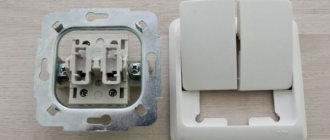
- two plastic or polypropylene mounting boxes (socket boxes), they are needed in order to securely fasten the switching devices in the wall openings;
- indoor socket;
- indoor switch with one key;
- lighting fixture;
- set of screwdrivers (flat and Phillips);
- knife or stripper for removing insulation from conductors;
- pliers with insulated handles;
- clamps or insulating tape;
- indicator screwdriver.
To switch the entire electrical circuit, you will also need a two-core wire. Nowadays, electrical goods stores offer a huge assortment of wires and cables, so immediately buy one so that each core has its own colored insulation, for example, red and blue. This will make it easier to switch the circuit; you won’t have to look for phase and zero with instruments, you’ll just need to connect wires of the same color.
Read also: How to connect a DRL via a button
In order to fix the wires laid in the grooves, you will also need alabaster and a spatula.
Installation features
block
It will not be difficult to install a combined unit without the involvement of a professional electrician, since connecting modern models requires a minimum of wires.
The installation process will have only a few features that need to be taken into account:
- You need to prepare the necessary tools in advance; you won’t need many of them: an electric drill with a drill core; several screwdrivers of different sizes; pliers and wire cutters.
- To ensure safety during work, make sure that the handles of all tools are insulated.
- Some modern varieties are designed for external installation, that is, when installing them, you can completely avoid drilling holes in the wall surface.
- You can choose a variety with an increased level of protection from environmental conditions; such models can be installed not only indoors, but also outdoors. Such devices also have an additional element in the design in the form of a special lid that helps prevent liquid from getting inside the device.
- All modern types of blocks are suitable for installation in walls made of any material and regardless of the type of finish.
Connection diagram
The electrical circuit represents a parallel connection to the power source of a lighting fixture with a light bulb, a switch and a socket.
Preparatory work
After turning off the machine, you need to once again make sure that there is no voltage, now using an indicator screwdriver. First, check its working condition in an area that is known to be energized, for example, at the entrance to the machine. The indicator lights up after touching the phase, which means it is in good condition. Now touch the indicator screwdriver to the cores of the power wire, which is brought into the apartment from the machine; there should be no glow. This means that the tension has been relieved and work can begin.
Lay the wires in the grooves made, leading them to the wall holes. At the same time, leave the ends of 10-15 cm for cutting the cores, do not regret it, it is better to make a slightly larger reserve than to suffer later when connecting and connecting. Install a distribution box and socket boxes in the holes; use plaster or alabaster to securely fix them.
Electric installation work
Place a two-wire cable from the mains supply (phase and neutral) into the junction box. Three wires must be laid from the box: one to the switch, the second to the lamp, the third to the outlet.
For a wire whose cores have different insulation colors, red indicates phase, blue indicates zero.
The switch has an input and output contact; a phase conductor is connected to the input. Connect the second core to the output contact of the switch.
A two-wire wire must also be laid to the lamp. The lamp socket has two contacts. The central spring contact (phase) is used to directly supply voltage to the light bulb. The side contact in the socket is zero, the lamp will come into contact with it after screwing in with its base.
Another two-wire wire is laid from the junction box to the outlet. This switching device has a contact part consisting of two terminals to which phase and zero are connected.
The connection diagram for the switch, lamp and socket in the distribution box is as follows:
- Connect the neutral conductor from the supply wire with the neutral conductors going to the lamp and socket.
- Connect the phase conductor from the supply wire with the phase conductors going to the switch and socket.
- Connect the remaining core from the output contact of the switch to the phase core of the lamp.
All connections must be made as firmly as possible to ensure reliable contact. This can be done the old fashioned way - by twisting, which it is also advisable to solder on top. There are also more modern devices: special blocks (in which the wire is clamped under a screw) or PPE (connecting insulating clamps).
For more information about connecting wires in a junction box, watch this video:
Checking the circuit and completing the work
Move all the twists in different directions so that they do not touch each other and check the operation of the assembled circuit. Turn on the input circuit breaker for the apartment, thereby supplying voltage from the power source to the newly mounted distribution box. The switch is in the “off” position, the lamp does not light, which means everything is correct, the phase is open. Now press the switch key to the “on” position, the electrical circuit is closed and voltage is supplied through it from the power source to the lamp, the light bulb lights up. There will be constant voltage at the outlet; you can check its operation by connecting any electrical appliance. Plug the hair dryer, radio or electric kettle into the outlet and check its operation.
Now turn off the input circuit breaker again and securely insulate the twisted areas with electrical tape; you can also put PVC pipes on top. Carefully place all the connected wires in the box so that it can then be closed with a lid.
All that remains is to securely place the switch and socket in the socket boxes, secure them, and put protective covers on top. The distribution box is also covered with a lid; during any repair work, never hide it under wallpaper or plaster. Remember, the distribution box should always be accessible, no matter how much it spoils the overall appearance of your room.
Also keep in mind that if the lighting fixture and socket are structurally grounded, then their electrical circuit will require a three-core wire. The same wire of three cores should also come to the junction box from the power source. Typically, the grounding conductor is indicated in green or yellow; in the same way, in the box you will need to connect three protective grounding conductors into one twist - from the power source, socket and lamp.
Welding
Using this method, at the end of the work you will receive an essentially solid cable. He will not be afraid of oxidation processes or any other negative impact characteristic of disconnected wires.
To complete the work you will need the following elements:
- welding machine;
- sandpaper;
- flux;
- personal protective equipment – gloves, goggles;
- carbon electrode.
At the first stage, you need to clean the cables from insulation and strip the wires until shiny using sandpaper. Then twist the wires together. The third step will be to fill the recess of the carbon electrode with flux.
Afterwards, it is necessary to put the welding machine into working condition, press the electrode to the place where the cables are twisted and hold it there until a ball is formed, in other words - a contact point.
The resulting contact point must be cleaned of flux and coated with a special varnish. At the final stage, you need to insulate the connection.
Other scheme options
In a similar way, you can connect a socket, a two-key switch and two groups of lighting fixtures from one power source. In this case, the distribution box will receive two wires from two output contacts of the switch and two phase conductors from the lamps. The same as in the example described above, only there will be one more twist in the box.
If you need to install a three-key switch and three groups of lamps, then three wires from the three output contacts of the switch and three phase conductors from the lighting devices will arrive in the distribution box. There will be 5 twists in total in the box:
- Zero supply network with zero wires of the socket and lamp.
- Power supply phase with phase conductors of socket and switch.
- And three twists of phase wires extending from each switch key and group of lamps.
In the case of protective grounding, another twist will be added. Sometimes it can be quite problematic to arrange twisted wires in a junction box. Now on the electrical goods market you can select options specifically designed to accommodate a large number of wires and cables.
This is how you can easily connect a socket and a switch from one junction box. The main thing is to try to understand this very simple scheme. And then all further electrical circuits will be clear to you. As a result, you will get quite a decent cost savings on calling a professional electrician.