Application and control circuit of independent release
Finally found a minute to write a new article.
An independent release is an additional device to circuit breakers. Now we will talk about the use of an independent release in our projects and how to correctly connect an independent release. RN-47
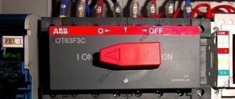
An independent release allows you to remotely open a circuit breaker or load switch. Most often, independent releases are used when designing ventilation. According to regulatory documents, ventilation must be turned off in case of fire, therefore, in addition to the input device of the ventilation panel, an independent release is installed. Switchboards up to 100A are equipped with modular circuit breakers. A load switch can be installed at the input to the switchboard. It is the input device that we turn off using an independent release. With a current of more than 100A, a BA88 series circuit breaker can be installed at the input to the switchboard. An independent release can also be installed on this device. In my projects it has not yet been necessary to remotely turn off the BA88 =)
Now let's move on to the connection diagram for the independent release.
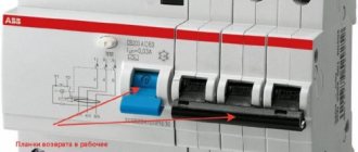
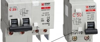
The independent release can disconnect both single-phase and three-phase devices. To activate the independent release, it is enough to apply a voltage pulse to the release coil. To restore the machine to its original state, you must manually press the “return” button. This allows you to signal why the circuit breaker tripped: either from an overload (short circuit) or from a remote shutdown.
The independent release control circuit is presented below.
Independent release control circuit
It is very important here that the phase conductor is connected from one of the phases from under the lower terminals of the circuit breaker. If connected incorrectly, the independent release will be damaged.
After the machine is turned off, the voltage from the release coil disappears.
The control signal for triggering the independent release can be a closing contact from a fire alarm device or a regular button with a closing contact.
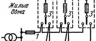
Sometimes a situation may arise when you need to turn off several independent releases at once with one signal. For example, you have 2-3 fans, which make no sense to separate them into a separate cabinet. Therefore, we install our own independent release for each group. This topic was raised on the forum...
The control diagram for several independent releases from one signal is presented below.
Control circuit for multiple independent releases
The main thing here is that the same phase is used.
It is worth noting that an independent release is not a cheap pleasure. Its size is the same as that of a single-pole circuit breaker (1 module), but costs an order of magnitude more.
I recommend reading:
Control circuit for outdoor lighting, advertising, backlighting
Optimal layout of an apartment electrical panel
Fire and smoke damper control diagram
What is the difference between “AND” and “OR”?
General device
Each model of independent release is presented in the form of a high-quality unit used for remote shutdown of protective equipment. Such a unit is operated together with modern circuit breakers that have one, two, three or even four poles. Most often, craftsmen connect the release to the input circuit breaker, and in the event of any emergency, the electrical panel is completely de-energized.
The design of the unit is more like a magnet. When it is affected by a short-term impulse, the device uses a special lever to act on the operating mechanism, which disables the automated protective device. In addition, the design provides for the presence of an electromagnetic coil , which can have different power indicators. The product can be designed for direct or alternating current with voltages of 110-415 V and 12-60 V. It all depends solely on the chosen model. The method of attachment to the machine also depends on the modification.
It is worth noting that the timely operation of the entire system depends on the correct connection of the release with the protective device. The master must comply with all the requirements of the connection diagram. For example, phase conductors must extend from the lower phase terminals of the machine.
If this rule is not followed, this can lead to premature failure of the installation. When everything works correctly, the independent trip circuit breaker turns off in a timely manner, and the voltage from the device coil completely disappears.
Functionality check
Every master sooner or later encounters situations when he needs to ensure the integrity of the releases. This question is of particular interest to amateur installers and novice craftsmen. You can verify that the unit is working in this way:
At the initial stage, a visual inspection is carried out, when the technician carefully examines the entire box of the unit. It is very important to ensure that the body is intact and there are no deformations or cracks on it. Particular attention should be paid to the switch button. It should easily take the required position in any value. At the next stage, the automatic device is checked for timely disconnection of the network when certain unfavorable conditions arise. Specialists carry out this test on a universal unit, where each stage is carefully controlled
Fine tuning allows you to fix the response time of the release from the moment the increased voltage is applied. At the final stage, all that remains is to free the unit from the walls of the housing and monitor it under the influence of powerful equipment. When a current leak is observed, the plate heats up in a matter of seconds and becomes deformed, which signals that the machine lever is turned off.
It is worth noting that any checks of the operation of independent releases for operation should be carried out exclusively in specialized clothing and under the supervision of a qualified specialist.
Model IEK PH47
This independent release (photo shown below) is quite in demand. First of all, it is important to mention its compactness. A small capacitor unit is used to connect to the shield. In total, the model uses two rectifiers. The contacts in this case are of the movable type. The expander itself is located in the lower part of the structure along with the relay. There is no transceiver in this case.
If we talk about the parameters of the release, it is important to note that it maintains the output voltage at 40 V. The threshold overload of the model is 30 A. The minimum permissible temperature of the release does not exceed -10 degrees. The model is not afraid of high humidity. The protection system is standardly used with the IP30 marking. The wiring in this case is used with insulators for safe operation.
ALEX1887 › Blog › How does a circuit breaker work?
In normal operation mode, a current flows through the machine that is less than or equal to the rated value. The supply voltage from the external network is supplied to the upper terminal connected to the fixed contact. From the fixed contact, current flows to the movable contact closed with it, and from it, through a flexible copper conductor, to the solenoid coil. After the solenoid, the current is supplied to the thermal release and after it to the lower terminal, with the load network connected to it.
In emergency modes, the circuit breaker disconnects the protected circuit by triggering a free tripping mechanism driven by a thermal or electromagnetic release. The reason for this operation is an overload or a short circuit.
The thermal release is a bimetallic plate consisting of two layers of alloys with different coefficients of thermal expansion. When an electric current passes, the plate heats up and bends towards the layer with a lower coefficient of thermal expansion. When the specified current value is exceeded, the bending of the plate reaches a value sufficient to activate the release mechanism, and the circuit opens, cutting off the protected load.
The electromagnetic release consists of a solenoid with a movable steel core held by a spring. When the specified current value is exceeded, according to the law of electromagnetic induction, an electromagnetic field is induced in the coil, under the influence of which the core is drawn into the solenoid coil, overcoming the resistance of the spring, and triggers the release mechanism. In normal operation, a magnetic field is also induced in the coil, but its strength is not enough to overcome the resistance of the spring and retract the core.
How a circuit breaker works in overload mode Overload mode occurs when the current in the circuit connected to the circuit breaker exceeds the rated value for which the circuit breaker is designed. In this case, the increased current passing through the thermal release causes an increase in the temperature of the bimetallic plate and, accordingly, an increase in its bending until the release mechanism is activated. The machine turns off and opens the circuit.
The thermal protection does not operate instantly, since it will take some time for the bimetallic strip to warm up. This time can vary depending on the magnitude of the excess current from a few seconds to an hour.
This delay allows you to avoid power outages during random and short-term increases in current in the circuit (for example, when turning on electric motors that have high starting currents).
The minimum current value at which the thermal release must operate is set using an adjusting screw at the manufacturer. Typically this value is 1.13-1.45 times higher than the denomination indicated on the machine’s labeling.
The magnitude of the current at which the thermal protection will operate is also affected by the ambient temperature. In a hot room, the bimetallic strip will warm up and bend until it triggers at a lower current. And in rooms with low temperatures, the current at which the thermal release will operate may be higher than permissible.
The reason for network overload is the connection to it of consumers whose total power exceeds the calculated power of the protected network. Simultaneous activation of various types of powerful household appliances (air conditioner, electric stove, washing machine, dishwasher, iron, electric kettle, etc.) may well result in the thermal release being triggered.
In this case, decide which consumers can be disabled. And don’t rush to turn on the machine again. You still won't be able to cock it into the operating position until it cools down and the bimetallic release plate returns to its original state. Now you know how a circuit breaker works during overloads
How does the circuit breaker work in short circuit mode? In the event of a short circuit, the operating principle of the circuit breaker is different. During a short circuit, the current in the circuit increases sharply and many times to values that can melt the wiring, or rather the insulation of the electrical wiring. In order to prevent such a development of events, it is necessary to immediately break the chain. This is exactly how an electromagnetic release works.
The electromagnetic release is a solenoid coil containing a steel core held in a fixed position by a spring.
Types of machines
The classification of circuit breakers is based on their types and features. As for types, we can highlight the following:
- Rated breaking capacity - we are talking about the resistance of the switch contacts to the effects of high currents, as well as to conditions in which deformation of the circuit occurs. Under such conditions, the risk of burning increases, which is neutralized by the appearance of an arc and an increase in temperature. The higher quality and durable the equipment is made of, the higher its corresponding capabilities are. Such switches are more expensive, but their characteristics fully justify the price. Switches last a long time and do not require regular replacement
- Rating calibration refers to the parameters within which the equipment operates normally. They are installed at the production stage of the equipment, and are not regulated during its use. This characteristic allows you to understand how strong overloads the device can withstand, the period of time it operates in such conditions
- Setpoint - usually this indicator is displayed as a marking on the equipment body. We are talking about maximum current values under non-standard conditions, which, even with frequent shutdowns, will not have any effect on the operation of the device. The setting is expressed in current units, marked in Latin letters and digital values. The numbers, in this case, reflect the denomination. Latin letters can be seen in the markings of only those machines that are manufactured in accordance with DIN standards
Table of different types of machines
Principle of operation
To protect the household electrical circuit from adverse effects, craftsmen use high-quality automated switches of a modular design. The great demand for such units has arisen due to the fact that they are compact in size, and are also easy to install and repair.
Externally, such devices are presented in the form of a conventional case made of heat-resistant plastic. The main on and off button is located on the front surface. On the rear panel there is a latch for installation on a DIN rail, and on the bottom and top there are screw terminals.
During normal operation, the unit carries a current less than or equal to the rated value. The top terminal receives power from the external network (this node is securely connected to the fixed contact). Next, electricity is supplied to the main thermal release, and after it - to the lower terminal and the load network connected to it. In emergency situations, the circuit breaker disconnects the protected circuit. An independent device is responsible for performing this function. The reason for this operation may be any emergency situation:
- Voltage overload - short circuit in the circuit.
- The occurrence of overcurrents is an increase in the current strength in the electrical network that exceeds the rated value of the switch.
- Voltage fluctuations.
Model IEK PH50
This independent release is produced for pulse and phase switches. It is well suited for ventilation systems and drives. The current conductivity indicator is about 3 microns. The negative resistance parameter on the relay reaches a maximum of 46 Ohms. The transceivers in the release are of the two-pole type. In total, the model has three pairs of contacts.
They are mounted on special plates that are located above the relay. The modulator is provided by the manufacturer as an orthogonal type. It is prohibited to connect the model through a capacitor unit. Only a kenotron is suitable for this. The minimum permissible temperature of the release is -10 degrees. The output voltage on the relay reaches a maximum of 40 V.
Automatic safety switch with independent release
The independent release, as mentioned, is an additional element of the circuit protection device. It allows you to turn off the AV at a distance when voltage is applied to its coil. To return it to its original state, press the button on the device that says “Return”.
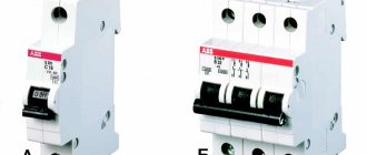
Circuit breaker releases of this type can be used in single-phase and three-phase networks.
The independent release is most often used in electrical circuits and automatic switchboards of large objects. Energy supply control in these cases, as a rule, is carried out from the operator’s console.
An example of an independent release triggering in the video:
What causes an independent type tripping element to trip?
An independent release can trip for various reasons. We list the most common of them:
- Excessive decrease or, on the contrary, increase in tension.
- Changing the specified parameters or the state of the electric current.
- Malfunction of circuit breakers, malfunction for an unknown reason.
In addition to independent tripping devices, there are similar elements included in circuit breakers. Built-in circuit breaker releases are divided into thermal and electromagnetic. These devices also help protect the line from excessive loads and short circuits. Let's look at them in more detail.
Electrical automaton: concept and necessity
An electrical circuit breaker, or circuit breaker, is a mechanical switching device through which you can manually de-energize the entire electrical network or a specific section of it. This can be done in a house, apartment, country house, garage, etc. Moreover, such a device is equipped with a function to automatically turn off the electrical cable in the event of emergency situations: for example, in the event of a short circuit or overload. The difference between such circuit breakers and conventional fuses is that after tripping they can be turned on again with a button.
Let's talk about how to choose machines: electric machines come in a wide variety, which requires taking into account a number of factors when purchasing them.
Is such an automatic machine needed? You must give an affirmative answer. A properly functioning circuit breaker will protect your premises from a variety of unpleasant situations, including:
- fires;
- electric shock;
- wiring damage.
So, when choosing a machine, as we noted, several indicators should be taken into account at once. Let's look at them in order.
Features of operation of network protection circuit breakers
Whatever class the circuit breaker belongs to, its main task is always the same - to quickly detect the occurrence of excessive current and de-energize the network before the cable and devices connected to the line are damaged.
Currents that may pose a danger to the network are divided into two types:
- Overload currents. Their appearance most often occurs due to the inclusion of devices in the network, the total power of which exceeds what the line can withstand. Another cause of overload is a malfunction of one or more devices.
- Overcurrents caused by short circuit. A short circuit occurs when the phase and neutral conductors are connected to each other. In normal condition they are connected to the load separately.
The design and principle of operation of the circuit breaker is on video:
https://youtube.com/watch?v=9bTw3wtgOWY
Overload currents
Their value most often slightly exceeds the rating of the machine, so the passage of such an electric current through the circuit, if it does not drag on for too long, does not cause damage to the line. In this case, instantaneous de-energization is not required in this case; moreover, the electron flow often quickly returns to normal. Each AV is designed for a certain excess of electric current at which it is triggered.
A thermal release, the basis of which is a bimetallic plate, is responsible for turning off the power under the influence of a powerful load.
This element heats up under the influence of a powerful current, becomes plastic, bends and triggers the machine.
Short circuit currents
The flow of electrons caused by a short circuit significantly exceeds the rating of the protective device, causing the latter to immediately trip, cutting off the power. An electromagnetic release, which is a solenoid with a core, is responsible for detecting a short circuit and immediate response of the device. The latter, under the influence of overcurrent, instantly affects the circuit breaker, causing it to trip. This process takes a split second.
However, there is one caveat. Sometimes the overload current can also be very large, but not caused by a short circuit. How is the device supposed to determine the difference between them?
In the video about the selectivity of circuit breakers:
Here we smoothly move on to the main issue that our material is devoted to. There are, as we have already said, several classes of AB, differing in time-current characteristics. The most common of them, which are used in household electrical networks, are devices of classes B, C and D. Circuit breakers belonging to category A are much less common. They are the most sensitive and are used to protect high-precision devices.
These devices differ from each other in terms of instantaneous tripping current. Its value is determined by the multiple of the current passing through the circuit to the rating of the machine.
Device sensitivity
Before you get acquainted with the types of machines, you need to find out with what sensitivity the devices are suitable for home use, and which ones will be inappropriate. This indicator will indicate how quickly the device will respond to a power surge. It has several markings:
Classification of machines
There are different types of machines in relation to the type of current, rated voltage or current indicator and other technical characteristics. Therefore, you need to specifically understand each point separately.
Current type
In relation to this characteristic, machines are divided into:
- For operation on AC power;
- For operation in a DC network;
- Universal models.
Everything is clear here and no additional explanation is needed.
Based on rated current
The value of this characteristic will determine in the network what maximum value the circuit breaker can operate with. There are devices that can operate from 1 A to 100 A and more. The minimum value with which machines can be found on sale is 0.5 A.
Rated voltage indicator
This characteristic indicates what voltage this type of circuit breaker can operate with. Some can operate on a network with a voltage of 220 or 380 Volts - these are the most common options for domestic use. But there are machines that will cope well with higher rates.
By ability to limit the flow of electricity
According to this characteristic, the following are distinguished:
Other characteristics
The number of poles can be from one to four. Accordingly, they are called single-pole, double-pole, and so on.
Automatic machines by number of poles
By structure they are distinguished:
Based on the discharge speed, high-speed, normal and selective devices are produced. They can have a time delay function that can be inversely dependent on the current or independent of it. The time delay may not be set.
Automatic machines also have a drive, which can be manual, connected to a motor or a spring. Switches differ in the presence of free contacts and in the method of connecting conductors.
An important characteristic will be protection from environmental influences. Here we can highlight:
- IP protection;
- From mechanical impact;
- Current conductivity of the material.
All characteristics can be combined in various combinations. It all depends on the model and manufacturer.
Switch types
The machine inside contains a release, which, using a lever, latch, spring or rocker, can instantly disconnect the network from the supply of electricity. Types of circuit breakers are distinguished by the type of release. There are:
Circuit breakers are much more cost effective than fuses. This is because after cooling, the machine can already be turned on, and it will work as it should if the cause of the overload is eliminated. The fuse needs to be replaced. It may not be available and replacing it may take a long time.
Automatic switches are designed to conduct current in normal modes and automatically switch off the protected circuit during short circuits (short circuits) and overloads, as well as for operational infrequent shutdowns.
Unlike high-voltage circuit breakers, the design of which contains contact, arc-extinguishing and drive systems and does not contain devices for measuring and monitoring the protected circuits (these devices are made at low voltage in the form of separate devices), low-voltage circuit breakers, as a rule, contain both structural units and devices for measuring and monitoring specified parameters of the protected circuit.
The designs, characteristics and protective functions of circuit breakers are very diverse. However, according to their purpose and design principles, they can be divided into general purpose switches, high-speed
and
special.
Automatic switches for general purposes.
According to the type of main circuit current, these switches are made of alternating current, direct current, alternating current and direct current.
Based on their own shutdown time, switches can be current-limiting or non-current-limiting.
Total short circuit duration ts.c., (Fig. 4-1, a
and
b)
consists of three terms:
to - time from the beginning of the short circuit until the moment when the current reaches the value Iset, at which the switching device is activated in stationary mode;
toff ~
own shutdown time - the time from the moment the current reaches the set value until the moment the contacts begin to diverge;
tr is the duration of the arc extinguishing process.
The time tо depends mainly on the circuit constants. Time toff
determines the speed of the switch.
A current-limiting switch
is
a switch whose own shutdown time is such that in a given circuit during this time the current does not have time to reach the steady-state value Is.c.
and the disconnected current Ioff is less than what would be in the circuit in the absence of a switch or with a non-current-limiting switch (Fig. 4-1, a). In Fig. 4-1, as an example, shows the current-limiting characteristics of some A-3700 series circuit breakers. Here Ik.z. — possible short circuit current; Ioff - current switched off by the switch (limited); direct 1 -
current that would turn off a non-current-limiting switch.
Rice. 4-1. The shutdown process in case of a short circuit: a – with a non-current-limiting switch; b and c – current-limiting switch.
Non-current-limiting
switches
can be with or without a time delay in the short-circuit current zone. The first ones are designed to implement selective protection, the essence of which is that at current Is.c. (Fig. 4-2), exceeding the setting current Iyct of circuit breakers of all stages, the section closest to the accident site is switched off, in which the circuit breaker has a shorter time delay t1 (t1
Automatic high-speed switches
(until now these are DC switches). The switches are designed to protect semiconductor converters, electrical machines and DC lines during short circuits, overloads and reverse currents in industrial installations (for example, in electric drives of rolling mills) and in installations of mainline, industrial and urban electrified transport.
Rice. 4-2. Scheme of selective protection.
In these modern installations, in particular in installations with semiconductor converters, short-circuit currents reach 200-300 kA. Semiconductor devices, unlike electrical machines, do not allow overloads. Due to their nature, their Joule integral is much lower than that of electric machines and other electromechanical devices. All this requires accelerated shutdown of the emergency section and limiting the current in the circuit.
One more very important circumstance should be taken into account - the presence of enormous electrodynamic forces that arise at the indicated currents. For example, in a circuit in which the short-circuit current can reach a steady-state value of 300 kA, with an initial rate (slope) of rise of 4.5 106 A/s to a circuit breaker with a shutdown time toclose =
0.08 s it is necessary to turn off a current of 280 kA, with toff = 0.04 s - a current of 160 kA, and a high-speed switch with toff = 0.005 s - a current of about 22 kA. Electrodynamic forces here are limited by 50-150 times.
According to the protective characteristics, our standards (GOST 2585-81 E) regulate the opening time of a high-speed circuit breaker, depending on the shutdown current and the steepness of its increase: 1st class - up to 0.008 s, 2nd class - up to 0.005 s, 3rd class - up to 0.002 s.
On alternating current, the rated currents in installations are limited by switching to higher voltages - at 220, 380 and 660 VV, currently at 1140 V. The increase in the power of installations poses the task of creating high-speed switches on alternating current.
Drive unit.
The drive is used to turn on the switch upon someone’s command (operator, automatic control system, etc.). Switches are made with manual or motor drive or with both. By motor drive we mean a drive in which the force is created by any type of energy other than the muscular energy of the operator, for example, an electromagnet, electric motor, pneumatics, hydraulics, etc. The switch is turned off by springs after the release device is disconnected.
Rice. 4-3. An example of a circuit breaker tripping device
Release device.
This device is intended:
to exclude the possibility of holding the switch contacts in the on position (with a handle, remote drive) in the presence of an abnormal operating mode in the protected circuit;
to ensure instantaneous shutdown, i.e., the speed of contact divergence independent of the operator, type and weight of the drive.
The tripping device is a system of hinged levers connecting the switching drive with a system of movable contacts, which are connected to the tripping spring. The operating principle of the device can be explained by the diagram in Fig. 4-3.
Scheme in Fig. 4-3, and corresponds to the “Manually switched off” and “Breaker charged” positions. “Cocked” means that contacts 7 and 8 are open, and the figured lever 9 is engaged 4
shut-off roller 5;
this is done by turning handle 1
to the right.
When the handle is turned to the left, the disconnecting spring 2 will move the “breaking” levers 3 and b through the dead position until the hinge stops O
into lever 9 and close the contacts. The “on” position is shown in Fig. 4-3.6.
In the event of abnormal operating conditions in the protected circuit, the corresponding release will rotate the tripping roller and disengage it from the figured lever. Under the action of the disconnecting spring, the figured lever will turn and its other end will move the “breaking” levers to the right through the dead position. The disconnecting spring will “break” the levers and open the contacts. The switch will be in the “Automatically off” position (Fig. 4-3, c). To turn it on again, you need to move the handle to the right and engage the figured lever with the shutdown roller.
The designs of tripping devices are very diverse, but their action is similar to that described. In what follows, we will depict the tripping device schematically in the form of two linked levers.
What types of independent releases are there?
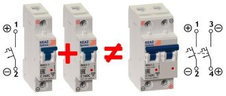
It is not possible to use an arbitrary independent release: the release must be of the same series as the circuit breaker being switched off. Different manufacturers have different series of electrical equipment.
There are independent releases that are triggered by voltages of 12, 24, 60, 110, 220V.
Not all models of independent releases have both high- and low-current versions.
For some independent releases, writing “low-current” does not raise your hand, since the operating current at 12V is stated to be 6A. The “low-voltage” version of the independent release also does not mean 12V - so I may be confused in terms.
Very few models of low-current independent releases have the ability to operate from 12V - 24V independent releases are more common.
A series of electrical equipment, in addition to an independent release, must also contain an additional signal contact.
A release is connected to the machine on the right, and a signal contact is connected to the left.
Or vice versa.
There are also independent releases with an integrated signal contact.
But using this contact to transmit a signal to the alarm system is problematic for some models, since one pole of the contact can be combined with the control line.
The contact is intended for signaling in high voltage circuits. And to stop supplying the control signal after the release is triggered to limit the time the coil is energized.
If any independent release for 220V can be used, then the low-current release must have an operating current of no more than the maximum current of the APS output.
Not all independent releases have accompanying documentation containing the tripping current.
Here are the control signal parameters for the most common “S2C-A” releases for ABB S200 series circuit breakers:
Similar currents are declared for similar independent releases.
Therefore, the question arises when the documentation for the release indicates a significantly lower current - is there a catch here?
Typically, a lower current is required to trip the residual current circuit breakers.
The ABB F2C-A1 release for residual current circuit breakers of the F200 series has the following parameters:
It is already possible to obtain a 12V 0.88A signal from a fire alarm system, but not all equipment can be connected through the F200 series residual current switch.
We will consider specific models of independent releases in the article Independent releases: characteristics and prices.
30 A modifications
30 A releases are manufactured with code extenders. The output voltage of the models is 35 V. As a rule, rectifiers are used of the diode type. In this case, the contacts are installed on movable plates. Transceivers are used with trimming resistors. Many models are connected to panels via capacitor units. In order to avoid large circuit overloads, expansion dinistors are used.
Some releases are made on the basis of a two-pole transceiver. Their distinctive feature is high current conductivity. This parameter fluctuates around 6 microns. However, the disadvantage of such systems is the rapid wear of the capacitors. It is also important to note that the models are not suitable for impulse switches.
Installation
Many home-grown electricians believe that installing a machine is not difficult. This is fair, but certain rules must be followed. Circuit breaker releases, as well as plug fuses, must be connected to the network so that when the plug of the circuit breaker is turned out, its screw sleeve is without voltage. The connection of the supply conductor for one-way power supply to the machine must be made to the fixed contacts.
Installation of an electric single-phase two-pole circuit breaker in an apartment consists of several stages:
- securing the switched-off device to the electrical panel;
- connecting wires without voltage to the meter;
- connecting voltage wires to the machine from above;
- turning on the machine.
Fastening
We install a DIN rail in the electrical panel. We cut it to the required size and fasten it with self-tapping screws to the electrical panel. We snap the automatic circuit breaker onto the DIN rail using a special lock, which is located on the back of the machine. Make sure that the device is in shutdown mode.
Connection to the electricity meter
We take a piece of wire, the length of which corresponds to the distance from the meter to the machine. We connect one end to the electric meter, the other to the terminals of the release, observing the polarity. We connect the supply phase to the first contact, and the neutral supply wire to the third. Wire cross-section – 2.5 mm.
Connecting voltage wires
From the central electrical distribution panel, the supply wires are connected to the apartment panel. We connect them to the terminals of the machine, which must be in the “off” position, observing the polarity. The wire cross-section is calculated depending on the energy consumed.
Turning on the machine
Only after all the wires have been installed correctly can the automatic current release be put into operation.
It happens that the constant shutdown of the machine becomes a big problem. Do not try to solve this problem by installing a trip unit with a higher current rating. Such devices are installed taking into account the cross-section of the wires in the house, and, perhaps, a large current in the network is unacceptable. The problem can only be solved by inspecting the electrical supply system of the apartment by professional electricians.
The independent release is an addition to the protective device for the electrical network. It is mechanically connected to the circuit breaker. An independent release performs the function of breaking the circuit when factors are detected that can lead to damage to the line and the devices included in it. These include an increase in current strength above the limit that the cable can withstand, a breakdown of electric current to the ground or the body of a device connected to the circuit, as well as a short circuit. This material will help you understand what circuit breaker releases are, what types of this device there are and what the operating principle of each of them is. In addition, we will tell you how to check the functionality of these elements.
Deciding on the denomination
Actually, from the functions of the circuit breaker, the rule for determining the rating of the circuit breaker follows: it must operate until the current exceeds the capabilities of the wiring. This means that the current rating of the machine must be less than the maximum current that the wiring can withstand.
For each line you need to choose the right circuit breaker
Based on this, the algorithm for selecting a circuit breaker is simple:
- Calculate the wiring cross-section for a specific area.
- See what maximum current this cable can withstand (see the table).
- Next, from all the ratings of the circuit breakers, we select the nearest smaller one. The ratings of the machines are tied to the permissible long-term load currents for a particular cable - they have a slightly lower rating (see the table). The list of denominations looks like this: 16 A, 25 A, 32 A, 40 A, 63 A. From this list you choose the appropriate one. There are smaller values, but they are practically not used anymore - we have too many electrical appliances and they have considerable power.
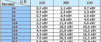
The algorithm is very simple, but it works flawlessly. To make it clearer, let's look at an example. Below is a table that shows the maximum permissible current for conductors that are used when laying wiring in a house and apartment. Recommendations regarding the use of machines are also given there. They are given in the column “Nominal current of the circuit breaker”. This is where we look for the ratings - it is slightly less than the maximum permissible for the wiring to work normally.
Cross section of copper wires
Permissible continuous load current
Maximum load power for single-phase network 220 V
Rated current of circuit breaker
In the table we find the selected wire cross-section for this line. Suppose we need to lay a cable with a cross-section of 2.5 mm 2 (the most common when laying to medium-power devices). A conductor with this cross-section can withstand a current of 27 A, and the recommended rating of the machine is 16 A.
How will the circuit work then? As long as the current does not exceed 25 A, the machine does not turn off, everything works as normal - the conductor heats up, but not to critical values. When the load current begins to increase and exceeds 25 A, the machine does not turn off for some time - perhaps these are starting currents and they are short-lived. It turns off if the current exceeds 25 A by 13% for a sufficiently long time. In this case, if it reaches 28.25 A. Then the power supply will work and de-energize the branch, since this current already poses a threat to the conductor and its insulation.
Power calculation
Is it possible to choose a machine based on load power? If only one device is connected to the power line (usually large household appliances with high power consumption), then it is permissible to make a calculation based on the power of this equipment. You can also choose an introductory machine based on power, which is installed at the entrance to a house or apartment.
If we are looking for the rating of the input circuit breaker, we need to add up the power of all devices that will be connected to the home network. Then the found total power is substituted into the formula, and the operating current for this load is found.
Formula for calculating current from total power
After we have found the current, select the nominal value. It may be either slightly more or slightly less than the found value. The main thing is that its shutdown current does not exceed the maximum permissible current for this wiring.
When can you use this method? If the wiring is laid with a large margin (this is not bad, by the way). Then, in order to save money, you can automatically install switches corresponding to the load, and not the cross-section of the conductors
But once again we draw your attention to the fact that the long-term permissible current for the load must be greater than the maximum current of the circuit breaker. Only then will the choice of circuit breaker be correct
Maximum breaking capacity
Ics/Icu and Icu
But this parameter is the most interesting, although not all manufacturers indicate it. This is the so-called maximum breaking capacity depending on voltage.
In simple terms, the following can be said about Icu. If the short-circuit current passing through the circuit breaker corresponds to this value indicated on the body, then the circuit breaker will successfully complete its task only once.
Then it will no longer be suitable for subsequent use. It will have to be replaced anyway.
If the short-circuit current is equal to the Ics/Icu parameter, then the machine can continue to be used.
These inscriptions are sometimes very important and allow us to evaluate the possibility of using the switching device at different rated voltages. As you understand, the short-circuit currents will differ significantly.
The breaking capacity of the circuit breakers has a quadratic dependence on the supply voltage. Look how significant this difference is.
Therefore, buying a machine for a single-phase 220V is not the same as for a three-phase 380V. Choose the wrong one and expect consequences at the first short circuit:
fire and burnout of the hull
abnormal hum the next time you turn it on, if the machine still “survived”
non-selective operation or contact sintering
It's good if it turns off for you altogether. In fact, the switch in this case turns into a fuse.
But its cost is several times different from the simplest devices with fuse links. The question is, was it worth overpaying?
Model Z-ASA/250
Why is the independent release Z-ASA/250 needed? This model is used exclusively for phase switches. Its current conductivity is 4.5 microns. The threshold overload of the device is no more than 24 A. The output voltage on the relay does not exceed 33 V. The rectifier is installed as a diode type. In total, the device has five pairs of contacts. The modulator for this release is of an orthogonal type. To connect the model, a capacitor unit is used, which is included in the standard modification kit.
If we talk about design features, it is important to note that the transceiver is used of a single-pole type. The manufacturer's protection system is marked IP30. The minimum permissible temperature of the release is no more than -15 degrees. The stabilizer is not provided in this configuration.
Methodology for checking the operation of circuit breaker releases
Disputes often arise that require clarification on how to correctly verify the performance of releases; amateur installers are especially interested in this, that is, people who cope with the installation of automatic equipment on their own.
First, carry out a visual inspection, that is, inspect the entire box
It is important that the body is intact and free of deformation; Try the switch key, make sure that it takes shape without difficulty in the on position, also in the opposite value; It is necessary to carry out loading, in other words, checking the automatic device for disconnection of the network under unfavorable conditions. This experiment is carried out on specialized equipment under the guidance of experienced electricians. With the help of certain abilities, the time of operation of the release is simply recorded from the moment the increased voltage arrives. Release the release from the walls of the housing and follow it under the influence of the equipment
When a current leak occurs, the plate should heat up and deform in a split second, and this is a signal to turn off the machine lever.
With the help of certain abilities, the time of operation of the release is simply recorded from the moment the increased voltage arrives. Release the release from the walls of the housing and follow it under the influence of the equipment. When a current leak occurs, the plate should heat up and deform in a split second, and this is a signal to turn off the machine lever.
When checking thermal response, the time during which the machine goes into the off state under the influence of voltage is recorded.
Induction coil release
What is the release used for? First of all, its tasks are considered to be the implementation of protection in relation to the electrical network from voltage, which may, even at a minimum, exceed the rated current value indicated in the device passport
Do not forget to pay attention to the class of the device, it indicates at what stage the supply of electricity through the circuit should stop
There is a difference in switching off the machine between the two types of releases, electromagnetic and thermal. For a split second, a machine equipped with an electromagnetic property will work faster.
Watch a short video about the principle of operation of the release using the example of the RMM-47 release:
A circuit breaker release (automatic) is an electrical device that turns off the network if a large electric current occurs in it. This device is used to ensure that if the wires overheat, there is no fire in the house, and expensive household appliances do not fail.
Types of machines
These products differ in the nature of the shutdown process when the highest current occurs. There are several main types of automatic devices. Each species differs in its sensitivity from each other.
Basically, in the production of electrical installations, four leading types are used: A, B, C, D. In addition, there are automatic machines of the MA, K and Z types.
Class A
Protective devices of this type have the highest sensitivity in relation to others. The thermal release of such a machine de-energizes the electrical circuit when the current increases by 30%. This process is carried out within 0.05 seconds if the current exceeds the rated value by 100%.
Type A automatic machine is not very popular among consumers, since the increased sensitivity does not allow even short-term increased loads, which cause constant operation of the device. These types are often installed in electrical circuits that have connections to semiconductor elements.
Class B
Category B protective equipment has less sensitivity than type B. The electronic release is triggered by an increase in current strength by 200% of the declared one, while the disconnection time from electricity is 0.015 seconds. If the release does not work for some reason, the bimetallic plate can turn off the electrical system in 4-5 seconds.
Such a device is used in electrical networks that have sockets, lighting and a starting device with the lowest value.
Class C
Type C devices are in great demand when installing household electrical networks. They are able to withstand the highest overloads. In order for the process of disconnecting a line from voltage to occur, the current flowing in a given line must increase 5 times its nominal value. In this case, the line is de-energized after 1.5 seconds.
These devices perform their protective functions well in general household networks. If in such networks sockets and lighting fixtures are powered separately, then in this case protection can be provided by class B devices. This action is carried out so that when a short circuit occurs, the entire house does not lose power.
Class D
These protective inventions can withstand network overloads up to 10 times the rated current. In this case, the electrical circuit is switched off within 0.4 seconds. Such devices have found their application in the protection of buildings and structures in general, that is, they are installed in addition to the automatic machines available in apartments.
They are turned off only when the automatic devices in individual rooms do not work. In addition, they are installed in lines with the highest inrush currents.
Design and principle of operation of a circuit breaker.
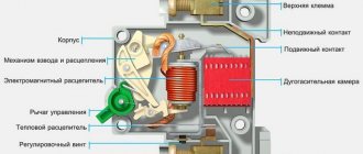
The figure below shows the design of a circuit breaker with a combined release, i.e. having both an electromagnetic and thermal release.
- 1 - body;
- 2,3 - lower and upper screw terminals for connecting the wire;
- 4 - fixed contact;
- 5 - moving contact;
- 6—arc chamber;
- 7 - flexible conductor (used to connect moving parts of the circuit breaker);
- 8 - cocking and release mechanism
- 9 — electromagnetic release coil;
- 10 — control lever;
- 11 — thermal release (bimetallic plate);
- 12 — adjusting screw;
The blue arrows in the figure show the direction of current flow through the circuit breaker.
The main elements of the circuit breaker are electromagnetic and thermal releases:
The electromagnetic release provides protection of the electrical circuit from short circuit currents. It is a coil with a core located in its center, which is mounted on a special spring. In normal operation, current passing through the coil according to the law of electromagnetic induction creates an electromagnetic field that attracts the core inside the coil, but the strength of this electromagnetic field is not enough to overcome the resistance of the spring on which the core is installed.
During a short circuit, the current in the electrical circuit instantly increases to a value several times higher than the rated current of the circuit breaker; this short circuit current, passing through the coil of the electromagnetic release, increases the electromagnetic field acting on the core to such a value that its retraction force is enough to overcome the resistance springs, moving inside the coil, the core opens the moving contact of the circuit breaker, de-energizing the circuit:
In the event of a short circuit (i.e., with an instantaneous increase in current several times), the electromagnetic release disconnects the electrical circuit in a fraction of a second.
The thermal release protects the electrical circuit from overload currents. Overload can occur when electrical equipment is connected to the network with a total power exceeding the permissible load of this network, which in turn can lead to overheating of the wires, destruction of the insulation of the electrical wiring and its failure.
The thermal release is a bimetallic plate. Bimetallic plate - this plate is soldered from two plates of different metals (metal “A” and metal “B” in the figure below) having different coefficients of expansion when heated.
When a current exceeding the rated current of the circuit breaker passes through the bimetallic plate, the plate begins to heat up, while metal “B” has a higher expansion coefficient when heated, i.e. when heated, it expands faster than metal “A”, which leads to curvature of the bimetallic plate; by bending it affects the release mechanism, which opens the moving contact. In a simple diagram it looks like this:
The response time of the thermal release depends on the amount of excess current in the electrical network of the rated current of the machine; the greater this excess, the faster the release will operate.
As a rule, the thermal release operates at currents 1.13-1.45 times higher than the rated current of the circuit breaker, and at a current 1.45 times higher than the rated current, the thermal release will turn off the circuit breaker in 45 minutes - 1 hour.
The operation time of circuit breakers is determined by their time-current characteristics (VTC)
Whenever a circuit breaker is turned off under load, an electric arc is formed on the moving contact, which has a destructive effect on the contact itself, and the higher the switched current, the more powerful the electric arc and the greater its destructive effect. To minimize damage from an electric arc in a circuit breaker, it is directed into an arc-extinguishing chamber, which consists of separate, parallel-installed plates; when the electric arc falls between these plates, it is crushed and extinguished.
Technical characteristics of the release
There are two types of tripping devices inside the machine. Each of them operates in its own current range. If both devices start working at the same time, this leads to the machine turning off when an overcurrent passes through it.
The thermal release mechanism operates by heating the bimetallic strip. It is calibrated and, at a certain current, heats up to certain levels. This causes a critical bend to occur and the machine to deactivate.
The second unit, electromagnetic, operates at a higher speed than thermal. It operates on the basis of an electromagnet that turns off the load when a short circuit occurs. The current of the electromagnetic switch is 3 times higher than the voltage of the thermal device. It can also be 20 times higher.
The automatic release is equipped with a diode rectifier. System dinistors are used with different conductivities. Devices for phase switches require the use of a transceiver. The relay is installed at the bottom of the system. The solenoid coil is usually rated for 12-60 V AC.
You might be interested in this: Remote electricity metering
Compact circuit breaker
Note! In some units, the voltage is kept at 110-415 V.
Model SHUNT 250 VAC
This independent release (the connection diagram is shown below) is made on the basis of a diode rectifier. It is located above the relay. If we talk about the device parameters, the negative resistance of the system is 44 Ohms. In this case, the threshold overload is no more than 24 A. To connect the modification, there is a compact capacitor unit. In this case, conductors are used with insulators. In total, the model has three pairs of resistors. They are located above the rectifier. In this case, the manufacturer does not provide a stabilizer. This model is ideal for low-power drives.
Model SHUNT 230 VAC
This independent release can only be used in conjunction with a phase switch. The model is ideal for remote control of the drive. The expander here is of the code type. Another feature worth noting is the presence of tuning resistors. Direct signal transmission is carried out thanks to a diode rectifier. The modulator is used in an orthogonal type circuit. The threshold overload of the system does not exceed 30 A. The minimum permissible temperature of the release is at -20 degrees.
Model S2C-A
This shunt release can only be used with impulse switches. The rectifier in the device is of diode type. The relay is used with an expander. The current conductivity indicator is no more than 4.5 microns. The transceivers are installed above the relays.
The stabilizer is not installed in the presented release. The model's contacts are located on plates. Signal transmission is carried out thanks to an orthogonal type modulator. The release is connected through a kenotron. Capacitor units are not suitable for this purpose. The minimum permissible temperature of the release is -10 degrees.