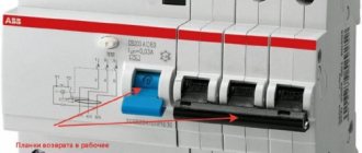
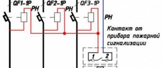
Installation and connection diagram
It is easy to establish experimentally that when overloaded, the machine will open the circuit regardless of where the input/output conductor is connected.
But according to the rules of electrical installations (PUE), the input must be connected to a fixed contact AB. It is not difficult to find this contact on the diagram printed on the device. Here is fixed contact No. 1.
This rule is determined by the internal structure of the machine, namely, the location of the arc extinguishing chamber. When the network is turned off, the spark “slides” towards the moving contact, is distributed over the comb and fades out. If you connect it the other way around, then each time it is disconnected, the spark will affect the working contact, destroying it.
For installation of most AVs used in everyday life, DIN rails are provided. Fastening is carried out with spring-loaded latches.
When tightening the screw clamp, use a screwdriver with suitable slots. This will help to apply enough force to securely fasten the wire.
Single-pole AVs are sold at any building materials and electrical store. By following simple rules when choosing, you can reliably protect your home from fire if the electrical wiring malfunctions.
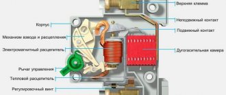
Machine device
The circuit breaker is a plastic case with contacts and an on/off handle. The working part is located inside. The stripped wire is inserted into the terminals and clamped with a screw. When cocked, the power contacts are closed - the handle position is “On”. The handle is connected to a cocking mechanism, which, in turn, moves the power contacts. Electromagnetic and thermal splitters ensure that the machine is switched off in case of abnormal circuit conditions. The arc chute prevents combustion and quickly extinguishes the arc. The exhaust channel removes combustion gases from the housing.
Features of DAV
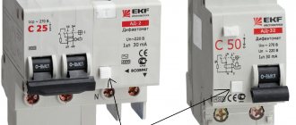
A special feature of the DAV is that it must break the electrical circuit when the permissible current in any of the supply wires is exceeded. Such a machine has 4 terminals, and the releases in it are triggered when the current regime is disrupted in both the phase wire (L) and the neutral wire (N).
Rice. 2. Two standard OAVs cannot replace DAVs
Therefore, two standard OAVs cannot replace DAVs. When the latter is triggered, both connected lines are de-energized simultaneously. If two single-pole AVs are used, then in this case one circuit will turn off, and the second can continue to work. And such an imbalance in some cases can lead to dangerous consequences, for example, during repair work.
Device characteristics
The design of the two-pole device is made taking into account the observation and comparison of the functioning of two electrical circuits. They are usually installed in a single electrical line to control its two sections. There are 2 types of these devices available:
- With one pole blocking and standard neutral wire connection.
- With protection of both lines and their simultaneous switching.
The first type is installed at the entrance to the electrical main, and it controls the functioning of the phase and neutral conductors. In addition, it is possible to use a grounding wire with this device. The second type operates in circuits of one circuit and controls the operation of two sections under different current loads.
Advantages and disadvantages
Two-pole circuit breakers provide control of lines with single-phase power supply, as well as protection of equipment operating in three-phase circuits.
The advantages of these devices include:
- reliable protection of homes, offices and industrial premises from network surges;
- the ability to control the power of individual electrical appliances and installations;
- ease of installation and maintenance. Two-pole AVs are ideal for branching and structuring wiring in the electrical supply of premises.
Of course, the main advantage is that a two-pole circuit breaker simultaneously de-energizes two conductors, regardless of which of them the accident occurred. This guarantees a complete absence of voltage in the protective conductors.
Disadvantages include:
- there is a possibility of cable breakdown when two loaded lines are turned on simultaneously;
- in rare cases, if the thermal release fails, an arbitrary power outage is possible even in the rated voltage mode;
- the need to select two-pole circuit breakers in accordance with the design parameters of the network. If the sensitivity of the switch is too high, it will often trip without good reason, and if the speed of reaction to an unusual situation is too low, the machine will not notice the network overload.
Thanks to the unique advantages, the use of two-pole switches is justified even taking into account the existing likelihood of the manifestation of these disadvantages.
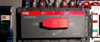
The structure and operating principle of a three-pole circuit breaker
A 3-pole circuit breaker consists of 3 single-pole devices housed in one housing and sharing a common switch lever. There are electromagnetic and thermal releases inside the protection device.
Internal organization
The electromagnetic release responds instantly to short circuit currents. According to the principle of operation, it resembles an ordinary electromagnet. If a short-circuit current flows through the machine, the electromagnetic release attracts the armature and sets the mechanics of the machine in motion. It opens the contacts of power circuits.
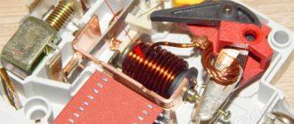
Circuit breaker design
The thermal release is similar to a bimetallic plate that is deformed by heat. It is characterized by slow response. To turn off the machine using the thermal release, it takes time for it to warm up to the desired temperature. Heat for heating is taken from the overload current flowing through the machine. Something similar is found in iron thermostats and kettle buttons.
Inside the differential automatic machines there is an additional unit - a current sensor. It is designed to compare currents flowing through phases. This design element allows the differential circuit breaker to turn off when voltage is lost in one of the phases. This function is especially important for the protection of electric motors.
Important! If your machine triggers without obvious overload, then you should pay attention to the reliability of its connection. Often, poor loose contact leads to heating of the machine. And heating leads to involuntary activation of the thermal release
And heating leads to involuntary activation of the thermal release.
Powerful three-pole circuit breakers have arc chutes. They are designed to interrupt the arc that forms between the contacts as quickly as possible at the moment the circuit opens. The use of arc chutes significantly extends the service life of the device. Thanks to them, contacts burn out much more slowly.
External elements
From the outside, the device has a standard design for protective devices. On top there are 3 screw terminals for connecting incoming wires. Below are similar screw contacts, but for the outgoing line. Between them there is an on and off lever. Many three-pole circuit breakers are equipped with a status indicator. Red flag or symbol “1” - the machine is turned on. Green or “0”—off. The main electrical parameters are indicated on the device body: rated current and time characteristic.
Additional Information. The design of some models of machines involves the use of a handle reminiscent of the one installed on the door. This handle is purchased at the buyer's request. Turning it turns the safety device on or off.
Where and how to use a three-pole circuit breaker to protect equipment
The three-pole circuit breaker is not a new concept used to protect three single-phase loads to save space and cost.
But what if the protected loads, for example electric motors, have different technical data and require different types of protection? In many applications - for example machines and installations with multiple loads - it usually makes sense to protect each load separately and individually.
Optimal electrical load safety
Individual protection, as opposed to group protection, ensures optimal safety for each electrical load from possible damage caused by overheating. In addition, the possibility of false positives is eliminated. If single-pole protection is sufficient, then such equipment protection circuit breakers can reliably cope with this task. Example: If three motors are to be protected in one unit, three single-pole circuit breakers will be required for this purpose.
Another alternative is to use three single-pole switches instead of one three-pole switch. This will significantly reduce installation time and space requirements. Additionally, in the event of a load failure, all three loads will always be disconnected from the supply voltage, including the faulty loads. This will ensure complete shutdown of the unit.
Three-pole circuit breaker and its features
However, a three-pole circuit breaker can only be used if the current ratings of the circuit breakers are matched to the operating characteristics of the loads. If the three loads to be protected are three identical electric motors, any standard three-pole circuit breaker can be used. But what if the motors you use require different switch ratings? Standard three-pole circuit breakers must be turned off because their three-pole chambers have the same ratings.
ETA thermal circuit breaker combinations such as the three-pole 3130 or the multi-pole push-button 3140 offer a potential solution. Their pole chambers can be equipped with various bimetallic releases. This allows users to select the required current values from the entire range of circuit breaker current values.
Types of Circuit Breakers
The 3130 three-pole rocker-operated circuit breaker can have 5 A bimetal in the first pole chamber, 10 A bimetal in the second chamber, and 16 A bimetal in the third chamber. The ETA 3130 and 3140 circuit breaker types have international approvals including VDE, UL, CSA and CCC, even though they are equipped with different bimetallic releases, and are therefore suitable for global use.
Multi-pole circuit breakers can be especially useful when used to protect single-phase or DC loads. If a multi-pole circuit breaker is intended to protect different loads, then the current ratings in the different pole chambers should be adjusted according to the load breaking limits. ETA circuit breaker combinations meet these requirements.
Is it possible to combine single-pole circuit breakers into two-pole or three-pole circuit breakers?!
General properties of switches
Regardless of how many poles there are in the switch, they perform one task - they protect the electrical network from short circuits in an emergency . Even 2 devices structurally combined in one box operate on the same principle.
A circuit break occurs when the rated current is exceeded. Power can be turned off if the circuit is overloaded or there is a risk of a short circuit. The heat distributor immediately sets the contact in motion, which blocks the flow of current. The devices have replaced fuses, while remaining compact, easy to operate, but significantly superior in reliability to their outdated counterpart.
What is the difference?
The purpose of a single-pole circuit is to disconnect only one line.
Two-pole circuit breaker:
- Work processes on 2 lines are controlled.
- The electron flow is compared.
- The compliance of the values with the standards is determined.
As soon as the indicator exceeds the norm, the device is triggered. The circuit will break completely and the current will stop flowing, unlike a switch with one pole.
If independent single-pole devices are connected, only one device will turn off when a problem occurs in the network. The voltage will remain in the faulty circuit, since the device will be turned on and the wiring may catch fire.
Circuit breakers play a common protective role, but they have a difference in their release. A two-terminal circuit has an element that turns off both parts when the machine is triggered or the handle is mechanically turned.
In apartments with a single-circuit circuit, complex automatic machines are not needed, since there is no complex equipment with different segments that require simultaneous protection. When devices are installed in a house that are not suitable for various reasons for a general network, you will need a multi-terminal network.
Application of two-pole circuit breakers
The scope of application of two-terminal circuits is very wide. Most often they are used in old apartments where single-phase two-wire wiring is installed, that is, where phase and zero are two absolutely identical wires. When connecting in a common switchboard, reversing the phase and zero is not an error, which is why in apartments it became necessary to disconnect both wires in the circuit. When installing a circuit breaker in a three-phase network, grounding wires must not be passed through it.
For the machine to operate correctly, a connection is required in the transformer panel, since it does not have a constant phase and zero. Therefore, when working with it, both lines must be turned off simultaneously.
Two-pole circuit breakers are also necessary to protect against burnout or breakdown of washing machines, refrigerators and other complex equipment, as they absorb sudden changes in network load and help reduce losses from overcurrents that occur during a short circuit to a minimum.
Device structure
Usually it is installed in a single-phase 220 V network, and to protect electrical lines with three-phase voltage, three-pole and four-pole circuit breakers are used. Important protection elements in a 2-pole circuit breaker are:
- electromagnetic mechanism;
- thermal release.
Electromagnetic protection mechanism
The design elements of this protection are triggered when a short circuit occurs in one of the lines. At the same time, large currents arise in the circuit, which can exceed the permissible value by several thousand times.
The solenoid is located inside a spring that connects the thermal release in series with the power contacts. The operating current is too small for the magnetic flux to pull in the core.
When the current increases sharply, the coil retracts the solenoid, compressing the spring, and it disconnects the contacts. In the normal state, the spring expands and the contacts are connected again.
Thermal release
A distinctive feature of this protective mechanism is that it operates much more slowly than the electromagnetic one. It is able to withstand the maximum load for some time, and if it does not drop to the operating value, it will disconnect the contacts. By the way, this mechanism does not react in any way to a short-term change in current strength.
The design of the release includes:
- bimetallic plate;
- release mechanism lever;
- contacts.
On what principle does a single-pole circuit breaker work?
Circuit breakers, like switching devices, perform the functions of conducting permissible electric current and turning off the power if the rating is exceeded, thereby protecting the electrical network from overload .
The task of a single-pole device is to protect the circuit in one wire . The operation of the device is concentrated on 2 distribution devices - thermal and electromagnetic . When the increased load lasts for a long time, the circuit is disconnected by the first mechanism. If a short circuit occurs, the second distributor immediately stops supplying power.
Thermal protection is performed by a plate made of composite material according to the following principle:
- A current exceeding the permissible level is supplied.
- The bimetal heats up.
- Bends.
- Pushes the lever.
- Turns off the device.
- The plate cools down.
When the condition of the bimetal returns to normal, it returns to its original state and the device can be reconnected. The electromagnetic device includes a coil in the middle of which a core is placed.
Here's the picture:
- A short-circuit current occurs.
- Enters the winding.
- The force created by the electromagnetic field moves the core.
- Disables the device.
During the interaction of physical processes, power contacts are opened , which de-energize the conductor.
A high current intensity creates an electric arc; it is directed into a chamber with parallel metal plates for crushing and complete disintegration. The machine can be turned off by simply turning the knob. Such switches are used in ordinary apartments if only 2 wires are connected to the house. In a barn or small private house, single-pole circuit breakers open the circuit. In apartment buildings there are grounding conductors, which means only a two-terminal network will do.
What if you choose the wrong machine denomination?
The main mistakes that are made when you need to choose a machine based on load power are: choosing a rating that is too high or, conversely, a current rating that is too small.
If you choose a device with a low rating, the circuit breaker will constantly turn off when electrical appliances are operating, lighting will disappear and important mechanisms will stop working. In this case, the laid cable will have a power reserve, but the circuit breaker will not allow a current higher than its rating to pass through it (which will be less than the rating of the cable).
In the second case, if you choose the wrong machine, with a “reserve” of power, you will expose yourself to the risk of fire in the electrical wiring. Since the power for which the cable line is designed will be significantly lower than the capacity of the circuit breaker and it simply will not work, since the electric cable will already melt, and the circuit breaker will still have a reserve of work.
Plus, the higher the nominal value of the machine, the more expensive it is. If you make such a mistake, you will overpay and expose yourself to significant risk, the operation of the electrical system will be ineffective and unsafe.
Very often a problem arises that the machine turns off or does not work correctly, but its nominal value is selected correctly. This happens because the device class, which is associated with the characteristics of the release, is incorrectly selected.
Double pole switch
A two-pole switch is connected to 4 wires . To 2 there is tension, the other half plays a protective role. The design of this device is almost no different.
The developer combined 2 single-terminal circuits into a single housing, so that in an emergency, 2 lines would be switched off at once. This does not mean that you can replace it with 2 single switches or install a jumper yourself. They do not have the locking mechanism found in the advanced unit.
Automatic machines for three-phase networks
Three-phase input provides some advantages compared to single-phase. This is the ability to use powerful energy consumers and ease of connection of electric motors
Using such a network, it is important to evenly distribute the load between all three phases to avoid voltage sags. It is advisable to use a four-pole input circuit breaker, and protect the outgoing lines with single-pole and three-pole circuit breakers
When choosing three-pole circuit breakers to protect equipment with electric motors, pay attention to the overload capacity of the machine. To avoid false alarms of the protective device, use machines with characteristic “D”
Machine characteristics
Essentially, this is a triple version of a single-pole device for an electrical circuit with three phases. The design feature is the presence of protective functions on each individual pole. The main characteristics are the permissible short-circuit current at which the circuit breaker trips and the cut-off speed.
There are two mechanisms for shutdown - electromagnetic and thermal. In the event of a short circuit, the electromagnet opens the circuit. Thermal is triggered by prolonged load exceeding the rated load. The device is also a switching device. If necessary, the machine can be used to turn the current on or off.
By design, the device has the following elements:
- control mechanism;
- power contacts;
- electric arc extinguishing unit;
- release;
- pole terminals for connecting wires.
Difference between double-pole and single-pole circuit breaker
The difference between a single-pole and a double-pole switch is that the first monitors the technical parameters of several lines. Accordingly, the difference between two and three-pole is that in the first two lines are monitored, and in the second - three lines. When the voltage in one is exceeded, the device protects each line. The second device protects only one power line. At the same time, it is impossible to replace a two-pole circuit breaker with several single-pole ones due to the shutdown lever. The interlock is designed so that if there is a problem, both lines will be disconnected. In addition, the current will not evaporate. It will penetrate into a properly working device and a fire may occur.
Difference between double-pole and single-pole circuit breaker
Advantages and disadvantages
The advantages include reliable protection, the ability to control power, and ease of installation and maintenance. The main advantage is the de-energization of several conductors, regardless of the occurrence of an accident in any of them. Thanks to this, tension is completely removed.
You might be interested in: Installation of an electric meter
The disadvantages of a multi-pole protective device are the possibility of cable breakdown by electric current during a simultaneous short circuit of several electrical networks.
Note! They also include turning off the power to the electrical wiring during a breakdown of the thermal release, the inability to turn on the power after an emergency line breakdown and sensitivity to mechanical damage
Specifications
Technical characteristics of two-pole circuit breakers vary depending on price and manufacturer. The rated voltage is 240 watts, the rated current is from 6 to 63 amperes, the number of poles is from 1 to 4, the time-current characteristic is designated B, C and D.
Technical characteristics of electrical equipment
Installation and connection diagrams
A two-pole circuit breaker is installed according to the electrification plan. The housing is checked for damage and deformation before installation. The operation of the shutdown handle must be of high quality. During installation, the connection of a copper conductor using a lug and the connection of an aluminum cable using an end piece are taken into account. The upper group of stationary circuit breakers, conductor sealing with insulating tubes and protective tape, the distance of nodes and the location of the additional box are also taken into account.
The machine is placed on part of the DIN rail. The latch bracket is removed using a flat-head screwdriver and placed on the rail with fasteners. During installation, the usual scheme is used. An input switch is placed before the meter, after it a two-pole type device is mounted, and a neutral with a phase is connected on top. The cores are routed from below to the circuit. Wired copper jumpers are used to connect multiple devices together. The end is cleaned using a sharp object and crimped using a crimper.
Note! During installation of the device, work must be carried out by two specialists wearing protective rubber gloves after obtaining permission from the housing and communal services. The connection must be made to the panel without damage at the mounting location
Device selection
To select a high-quality protective device, you need to focus on the conductor cross-section. To do this, you will need to calculate the power and current of the equipment and power line. Based on the displayed data, you can select a machine. As a rule, you can take all the information from special diagrams.
Criteria for choosing electrical equipment
A two-pole circuit breaker is a device designed to protect an electrical circuit. It has its own functional purpose, advantages and disadvantages. It also has its own technical characteristics.
You may be interested in this RCD connection
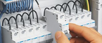
Installation of circuit breakers
The connection of circuit breakers in the distribution cabinet is carried out in a certain sequence. A cable connected to an external current source is inserted from above, and through the output holes located below, the wiring is routed to its objects, in accordance with the electrical diagram.
At the beginning of installation, the input circuit breaker is connected. If there are several lines in the circuit, isolated from each other, they are separated from the input circuit breaker. Its power must be no less than the total power of the machines connected to separate lines. For this purpose, two- or four-pole devices of group D are selected, resistant to the inclusion of power tools and other powerful equipment.
The most widespread are those suitable for any power supply schemes for apartments and private houses. Modular circuit breakers are installed on a DIN rail and connected by conductors with a current carrying capacity exceeding the operating current of the switch. A more convenient connection of several machines in one row can be done using a special connecting bus. A piece of the required length is cut from it and secured in the terminals. This connection is possible due to the distance between the bus contacts corresponding to the standard width of modular machines. The switch is installed per phase, and the neutral conductor is supplied from the input device directly to the devices.
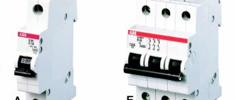
- A single-pole
switch is used when installing sockets and lighting systems. - A two-pole
circuit breaker is suitable for high-power appliances, such as an electric stove or boiler. In case of overload, it is guaranteed to break the circuit. The connection diagram of such switches is practically no different from single-pole models. For more efficient use, it is recommended to connect them to a separate line. - A three-pole
circuit breaker should be installed only in cases where it is planned to use electrical appliances operating at a voltage of 380 V. In order to eliminate the load, the load is connected in a “triangle” pattern. This connection does not require a neutral conductor, and the consumer is connected to its own switch. - A four-pole
circuit breaker is most often used as an input circuit breaker. The main condition for connection is the uniform distribution of the load on all phases. When connecting equipment in a star configuration or three separate single-phase wires, excess current will flow through the neutral conductor.
With all loads evenly distributed, the neutral wire begins to perform a protective function in the event of unexpected power imbalances. To ensure a normal connection, only high-quality materials should be used. All connections must be securely fastened to the terminals. If several cables are connected at once, their contacts must be thoroughly cleaned and tinned.
The procedure for connection can be considered using the example of a two-pole circuit breaker installed in the panel. First of all, the power is turned off to completely de-energize the network. The absence of electricity is checked using an indicator screwdriver or a multimeter. Then the machine must be installed on the DIN rail and snapped into place. The absence of a mounting rail can create certain inconveniences. After this, the cores of the incoming and outgoing wires are stripped to a distance of 8-10 mm.
Input wires are connected to two clamps located on top -. The lower clamps hold similar outgoing conductors distributed to sockets, switches and electrical appliances. All wires are properly clamped into terminals using screws. Connections must be checked manually. To do this, the conductors need to be gently moved from side to side. If the connection is poor, the core will wobble in the terminal and may even jump out of it. In this case, the terminal screw needs to be tightened.
Upon completion of installation, voltage is supplied to the network and the functionality of the circuit breaker is checked.
How to connect a two-pole machine
Connecting a two-pole circuit breaker yourself should not cause any particular difficulties, but entrust the matter to an electrician and do not risk working with potentially dangerous devices yourself. Of course, it’s easy to figure out how to connect everything with your own hands, but it is extremely undesirable to install such a mechanism alone - usually even electricians work on the connection in pairs. Therefore, it makes sense to ask someone to help and make sure nothing happens.
The installation of any mechanism of this type is carried out with permission. The procedure for obtaining it is simple; you only need to contact the housing and communal services or management company. If you don't do this, you risk getting a fine.
Attaching the device to a special metal rail is not difficult; just use a regular flat-head screwdriver to pull out the latch located on the back of the object’s body, place it on the special fasteners located on the rail, and release the fastener. The mechanism will latch itself, ensuring reliable fastening to the desired location. The wires are connected to the terminals with special clamping bolts. As a rule, the input wires of zero and phase are connected at the top, and the cores that need to be routed into the circuit are connected at the bottom.
The main thing is not to mix up the places where the wires are connected, otherwise the machine will simply fail.
How to choose based on device characteristics and functions
The main parameter by which a circuit breaker is selected is the total current load from all connected electrical appliances
You also need to pay attention to other factors - network voltage, number of poles, housing security, wire cross-section, condition of electrical wiring
Determining the polarity of the machine
Depending on the type of electrical wiring, the pole of the machine is selected. For single-phase networks, single- and two-terminal devices are used; for three-phase electrical networks, devices with three and four poles are used.
Current selection
Current is the most important characteristic influencing the choice of machine. It is this indicator that determines whether the protection will work in an emergency. For electrical panels located near electrical substations, a 6 kA protective device should be purchased. In residential premises this value increases to 10 kA.
Operating or rated current
Operating currents are determined by the total load of all household appliances that the machine protects. The cross-section of electrical wires and their material should also be taken into account.
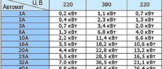
For the lighting group, 10 Amp circuit breakers are usually used. Sockets can be connected to 16 Amps. Heavy-duty appliances like electric stoves and water heaters require 32 amps at the circuit breaker.
The exact value is calculated as the total power of all household appliances divided by 220 V.
It is undesirable to greatly increase the operating current - the machine may not work in an accident.
Short circuit current
To select a circuit breaker based on short circuit current, you should use the rules of the PUE. It is prohibited to use switches with a breaking capacity lower than 6 kA. In homes, 6 and 10 kA devices are most often used.
Selectivity
This term refers to the disconnection in an emergency of only the problematic section of the electrical network, and not all the energy in the house. You should select machines for each group of devices separately. The input circuit breaker is selected for 40 A, then devices with a lower current are installed for each type of household device.
Number of poles
There are several types of machines: single-pole, two-pole, three-pole and four-pole. Single-terminal circuits are used in a single-phase network (one phase, two, three wires). The neutral is not protected in this case. Used for socket group or for lighting. A double pole switch is used for electrical wiring with one phase and two wires. Can be used as an input fuse for the entire network and to protect individual electrical appliances. Devices with two poles are the most common.
Replacing one two-terminal device with two single-terminal devices is prohibited by the rules of the Electrical Installation Code.
Three-terminal and four-terminal networks are used in a three-phase 380 Volt network. They are spilled by the presence of a neutral wire in a device with four poles.
Cable cross-section
The cross-section and material of the cables has a huge influence on the choice. Homes built before 2003 used aluminum wiring. It is weaker and needs replacement. It is impossible to install a new switch selected only by total power.
Copper cables carry higher currents than aluminum cables
Here it is important to take into account the cross-section - copper products with an area of 2.5 sq. mm. operate safely with currents up to 30 A
To determine the required value, use tables for calculating cable cross-section.
Manufacturer
You definitely need to pay attention to the manufacturer of the machine. It is better to purchase the device from a well-known, trusted company in a specialized store.
This will reduce the risk of buying a fake, and the purchased product will meet the stated criteria. Also, branded stores provide a guarantee on the switch.
Housing protection degree
Each switch has its own degree of housing protection. It is written as IP and 2 digits. Sometimes 2 Latin letters may be additionally used to describe auxiliary characteristics. The first number indicates the degree of protection from dust, the second – from moisture. The higher the number, the higher the security of the machine body.
Marking
The switch is marked with letters and numbers. It is deciphered as follows:
- letter A, B, C, etc. – class of the machine, means the instantaneous current limit;
- the number indicates the rated current at which the device operates in normal mode;
- A number in thousands of amperes is also indicated next to it, indicating the maximum current value at which the switch will respond.
The markings are indicated on the device body and in the relevant documentation.
Installation
How to properly install circuit breakers in an electrical panel? First, DIN rails are screwed into it with self-tapping screws - these are metal plates, onto which all automatic devices and RCDs are then attached. The length of the DIN rail can be adjusted using a hacksaw. In addition, distribution terminal strips are attached to the shield. They can be for neutral wires and separately for ground wires. The modern configuration of the tires allows them to be mounted directly on a DIN rail.
Installing a two-pole circuit breaker on a DIN rail is very simple. Using a flat-head screwdriver, you need to pull out the snap-on bracket on the top of the case, attach the machine to the DIN rail and release the fastener. Removal is also carried out. According to the rules, the introductory machine is installed in the upper left corner.
Next you need to connect the wires. The scheme must be strictly adhered to. The phase and neutral input wires are connected to the two-pole circuit breaker from above, and the wires from below are discharged into the circuit
It is important not to confuse: the entrance is from above, the exit is from below, otherwise the machine may fail and will not perform its functions
You can connect machines using jumpers made of copper wire of the same cross-section as the circuit wire. Jumpers are required to connect two-pole circuit breakers in a row. And also with the help of combs - these are insulated buses, used to connect single-pole circuit breakers.
The ends of the wires are stripped using a special stripper tool or a sharp knife. Then they crimp the cable lugs with a hand tool using a crimper. If there is no such equipment, then you can simply tin the ends with a soldering iron using rosin and tin. When connecting wires to machines, it is necessary to tighten the bolts firmly with a screwdriver so that weak contact does not cause heating and damage to conductive materials.
The grounding wire always passes past the machines directly to the grounding bus. The neutral wires are connected to the neutral bus.
RCD classification
The operating principle of a circuit breaker.
The RCD reacts to differential current, i.e. the difference in currents flowing through the forward and return wires. Differential current appears when a person touches a protected circuit and a grounded object. RCDs for protecting people are selected for a current of 10-30 mA
, fire RCDs - for a current of 300 mA. The latter protects the entire wiring system, and in the event of a fire, leakage currents usually occur earlier than short-circuit currents.
Residual current devices protect people from electric shock.
The choice of RCD is complicated by the fact that it is a more complex device than an automatic machine. For example, there are difavtomats - devices that combine an automatic machine and an RCD. RCDs are also divided by type into electronic and electromechanical. Experience has shown that it is better to use electromechanical RCDs. They are better protected from false alarms and breakdowns.
By number of poles
RCDs are divided into:
- bipolar for 220 V circuits;
- four-pole for 380 V circuits.
According to operating conditions
on the:
- AC
- responsive only to alternating sinusoidal differential current. - A
- responsive to both alternating sinusoidal differential current and constant pulsating differential current. - B
- responsive to alternating sinusoidal differential current, to constant pulsating differential current and to direct differential current.
Based on delay
on an RCD without a delay for general use and with a time delay of type S. According to the current characteristics (differencing devices) at B, C, D. And, finally, according to the rated current.
RCD circuit that responds to changes in housing voltage relative to ground.
You should know that if a conventional Residual Current Device and a circuit breaker are in series in the same circuit, then the circuit breaker must have a lower current than the RCD. Otherwise, the RCD may be damaged, because The machine breaks the load circuit with a delay.
In conclusion, it must be said that you should choose devices from well-known companies: ABB ab
,
GE POWER power
,
SIEMENS Siemens
,
LEGRAND Legrand
and others, at least certified in Russia. It is better to choose electromechanical RCDs, because They are much more reliable than electronic ones. Instead of a tandem of an RCD and an automatic device, it is better to choose a difavtomat, this will make the design of the shield more compact and reliable. Current ratings must be selected depending on the wiring used. The operating current of automatic devices and automatic devices must be less than the maximum permissible cable currents.
For copper three-wire cables, the following data corresponds to the cross-section of the cable conductors in square millimeters and the circuit breaker currents:
- 3 x 1.5mm2 - 16 Amperes;
- 3 x 2.5 mm2 - 25 A;
- 3 x 4 mm2 – 32 Ampere;
- 3 x 6mm2 – 40 A;
- 3 x 10 mm2 – 50 Ampere;
- 3 x 16 mm2 – 63 A.
We hope that after reading all the material it will be easier for you to understand the design and construction of electrical wiring.
Basic criteria for choosing a circuit breaker
Short circuit current limit
This indicator must be taken into account immediately. It means the maximum current value at which the electrical circuit breaker will operate and open the circuit. There is not much choice here, since there are only three options: 4.5 kA
;
6 kA
;
10kA
.
When choosing, you should be guided by the theoretical probability of occurrence of a strong short-circuit current. If there is no such probability, then it will be enough to purchase a 4.5 kA automatic machine.
Machine current
Taking this indicator into account is the next step. We are talking about the required nominal value of the operating current of the electrical machine. To determine the operating current, you need to be guided by the power that is expected to be connected to the wiring, or by the value of the permissible current (the level that will be maintained in normal mode).
What do you need to know when determining the parameter in question? It is not recommended to use machines with high operating current. It’s just that in this case, the machine will not turn off the power when overloaded, and this can cause thermal destruction of the wiring insulation.
Machine polarity
This is perhaps the simplest indicator. To choose the number of poles for a switch, you need to proceed from how it will be used.
So, a single-pole circuit breaker is your choice if you need to protect the wiring that goes from the electrical panel to sockets and lighting circuits. A two-pole switch is used when you need to protect all wiring in an apartment or house with single-phase power. Protection of three-phase wiring and load is provided by a three-pole circuit breaker, and four-pole circuit breakers are used to protect four-wire power.
Machine characteristics
This is the last indicator you need to pay attention to. The time-current characteristic of the circuit breaker is determined by the loads that are connected to the protected line. When choosing characteristics, the following are taken into account: operating current of the circuit, rated current of the machine, cable capacity, operating current of the switch.
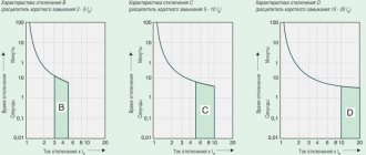
In the event that it is necessary to connect small inrush currents to the power supply line, i.e. electrical devices characterized by a small difference between the operating current and the current that occurs when turned on, preference should be given to response characteristic B. For more serious loads, characteristic C is chosen. Finally, there is another characteristic - D. Your choice should be made on it because if you plan to connect powerful devices with high trigger points. What devices are we talking about? For example, about an electric motor.