All modern mechanisms that facilitate labor and household work operate on the basis of electricity. For power supply, alternating current is used, supplied to the end consumer in three phases and the neutral of the power network.
When the line load is less than 10 kW, to power low-power equipment, it is enough to supply one of the phases, along with the neutral. This is what is usually done in relation to residential premises. Often there are only two wires entering an apartment or house. Although there are exceptions. For example, in some models of refrigerators, ventilation mechanisms or stoves, it is necessary to connect all three phases. Another thing is production, where powerful electric motors, welding, compressors and all other mechanisms are used that heavily load the power supply network. Supplying them with full-scale electric current ensures the necessary functionality while covering all emerging requests.
Powerful electric motors:
For mechanisms using full-phase power, there are some requirements for its characteristics. We are talking about the order and voltage in all three lines. If they differ from the standard or are connected incorrectly, the efficiency of the end devices will be lower. The latter mostly affects electric motors and current transformers. In order to comply with this condition of compliance, phase control relays for input lines are used.
What is it for?
A phase and voltage control relay is a device that is necessary when connecting equipment to a system with three phases, as well as in situations where it is important to maintain correct alternation.
In practice, the product is used when equipment is frequently transferred, when changing the phasing may cause damage or incorrect operation.
A striking example is a screw-type compressor, the incorrect connection of which and switching on for more than five seconds leads to breakdown of an expensive product.
The phase and voltage monitoring relay allows you to identify the following problems:
- Break of any phase;
- Increase or decrease in voltage above (below) a given level;
- Phasing violation (phase connection order);
- Break of “zero”;
- Asymmetry of I and U (here we are talking about phase imbalance, when the angle between the vectors is significantly more or less than 120 degrees).
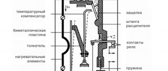
The schematic diagram of the device is shown below.
Some relays provide the ability to change the settings for the upper and lower limits U, as well as T (time) of operation.
As a rule, the output contact group of the relay is “dry”. In this case, there are two options available - normally closed and open. Some models have elements that operate on the induction principle.
Which is better: stabilizer vs relay
Often, instead of connecting a control relay in the panel, electricians recommend installing a voltage stabilizer in the house. In some cases this may be justified. However, there are a number of nuances that must be remembered when choosing one or another option for protecting electrical appliances.
In terms of functionality, the stabilizer not only equalizes the voltage, but also turns off when the voltage is too high. A voltage relay is an exclusively protective automatic device. It seems that the first includes the functions of the second.
But compared to the RKN stabilizer:
- more expensive and noisy;
- more inert during sudden changes;
- does not have the ability to adjust parameters;
- takes up much more space.
When the input voltage is reduced so that the output of the stabilizer has the required indicators, it begins to “draw” more current from the network. And this is a direct path to wiring burnout if it was not originally designed for this.
The second main disadvantage of the stabilizer in comparison with the control relay is its inability to intercept a sharp voltage surge when the zero is broken.
Literally half a second with 350-380 W in the outlet is enough for all the equipment in the house to burn out. But most stabilizers are not able to adapt to such changes and pass high voltage, turning off only 1-2 seconds after the start of the surge.
In addition to stabilizers and relays, overvoltage and undervoltage releases can also be used to protect the line from voltage surges in the network. But they have a longer response time compared to the RLV. Plus, they do not turn the power back on automatically; their operation is more like an RCD.
After a power outage, these releases will have to be reset manually.
Design and principle of operation
Despite the variety of voltage phase control relays, the design features are almost unchanged. The device is based on microprocessors with an embedded program and the ability to customize. This design ensures reliable operation and low maintenance.
The design of the product also includes a circuit that calculates the order of the arrangement (sequence) of phases, and also monitors the compliance of the current situation with the program that is embedded in the relay.
On the simplest models, three phases and a neutral conductor are connected to the input, and a relay with a changing contact is provided at the output terminals.
Voltage to the internal circuit is usually supplied from the first phase (L1). For clarity, a pair or more indicators are installed (much depends on the product model) and the manufacturer.
More expensive relays have a regulator that allows you to change the setting over time (see photo above). Thanks to this option, you can increase or decrease the relay response time when executing a specific program.
In addition, many devices have a circuit that responds to a decrease or increase in voltage.
The operation of the U phase control relay is based on the separation of negative sequence harmonics (from 2 and above). In this case, only harmonics that are multiples of “two” are used, that is, “fourth”, “sixth”, “eighth” and other harmonic components. They appear in the event of a break in any of the supply phases.
To isolate such U, special filters (also negative sequence) are used, the role of which is played by analog-type filters. They include active and reactive units (resistors and capacitors, respectively).
General settings of three-phase relay
The initial settings are of great importance for the further operation of the voltage relay. The order of their implementation can be considered using the example of the standard model VP-380V shown in the figure.
Once the relay is connected to the electrical circuit, power is supplied to it. The display will show all the necessary information:
- Flashing numbers indicate that there is no voltage in the network.
- If dashes appear on the display, this means a change in the phase sequence or the absence of one of them.
- When the parameters of the electrical network correspond to the norm, and the device is connected correctly, then after about 15 seconds contacts Nos. 1 and 3 close, power is supplied to the contactor coil and then to the network. That is, the device already monitors the state of all three phases.
- The display screen may blink for a very long time. This means that the contactor does not turn on. This situation most often occurs due to a connection error.
The three-phase voltage relay itself is configured using two setting buttons with printed triangles, which are located to the right of the screen. On the top button the triangle is pointing up, and on the bottom button the triangle is pointing down. To set the maximum shutdown limit, press the top button. She is held in this position for 2-3 seconds. After this, a number indicating the factory level will appear in the central row of the screen. Next, the upper button should be pressed until the desired value of the upper shutdown limit is set.
Setting the lower limit is done in the same way, only in this case the lower button is used. Once setup is complete, the device automatically reprograms after approximately 10 seconds.
Types
The most popular types of relays designed for phase control include EL models of the following series - 11, 12, 13, 11MT and 12MT.
It is important to take into account that the scope of application of the product depends on their types of voltage phase control relays (EL):
- 11 and 11 MT - protection of power supplies, participation in the automatic transfer system, power supply of converters and generator sets.
- 12 and 12MT - to protect cranes with a power not exceeding 100 kW.
- 13 - used when connecting electric motors of a reversible type with a power of up to 75 kW.
The devices are fixed on a special DIN rail or only with screws (depending on the situation).
Characteristics
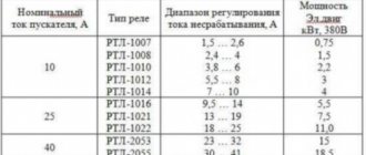
Modern phase control relays are selected taking into account the following characteristics:
- VOLTAGE. Operating U directly depends on the equipment specification. For example, EL Series 11 can operate at voltages from 100 to 415 V (including 110 V, 220 V, 380 V and 400 V). As for EL 13, they operate on voltages of 220 and 380 V.
- OPERATION LIMIT. This parameter also depends on the type of relay and the current situation. Thus, with a symmetrical decrease in voltage, EL series 11, 12 and 13 devices have a minimum limit of 0.7; 0.5 and 0.5 Ufn respectively. In the event of a break in one or more phases, all relays will operate. If the alternation is disrupted, then models EL11 and 12 recognize the problem and close the contact group, but EL13 does not.
- DELAY TIME. This indicator reflects how much the response of the voltage phase control relay is delayed when the required setting is reached (the specified threshold value). For models EL11 and 12 this figure is from 0.1 to 10 seconds (depending on the adjustment), and for EL13 - up to 0.15 seconds.
- WORKING TEMPERATURE. As in the cases discussed above, the situation here depends on the type of relay. EL types 11 and 12 operate from 40 degrees below zero to 40 degrees above zero. As for EL13, these relays have a smaller range - from -10 to +45 degrees Celsius.
- Storage temperature - from -60 to +50 degrees Celsius.
- Product weight - 300 grams (EL 11 and 13) and 250 grams (EL 12).
Subtleties of choice
When choosing a voltage phase control relay, you need to focus on the technical parameters of the device that is connected to the circuit.
For example, consider a situation when you need to select a model for connecting an ATS.
The algorithm of actions is as follows:
- WE DETERMINE THE CONNECTION METHOD - with or without “zero”.
- WE DETERMINE THE PARAMETERS. For an ATS circuit, it is important that the device monitors the fact of phase failure and the phase sequence. In this case, the delay time should be in the range between 10 and 15 seconds. Control of oscillations U greater or less than the set point is required. To switch a relay with the 0th wire, visual inspection is required for each phase.
After analyzing the requirements considered, preference can be given to EL11E.
In addition, when choosing, you need to take into account the modification of the relay. For example, domestically produced devices are designated as EL.
As for foreign products, their markings are somewhat different. For example, RANA B380 A A 3 C. Here “RANA” is the name of the series, B380 is the voltage 380V. The next two letters A are regulation using a potentiometer and the type of installation (for DIN rail). The number “3” indicates the case size of 3.5 cm, and C is the last digit of the marking.
How to set the restart time?
On the body of the device, next to the display, there is a button for setting the restart time. It is located between the ▲ and ▼ buttons, indicated by a clock icon. After pressing and holding it, the setting number set at the factory will appear on the display. Most often it is 15 seconds.
What does this feature do? If, for example, a potential difference occurs on one phase that exceeds the limit values, the relay will turn off the power to the network.
After the voltage is normalized, the control device will turn on the electricity supply after the period set at the factory (15 seconds). To change the value, hold the setting button until this number appears on the screen. After this, set the desired number by manipulating the upper or lower button. The change step provided by the device is 5 seconds.
Phase control relay EL-11E (380 V, 50 Hz), RKF, IEK
These phase control relay models are produced by, which has been on the market since 1992. The company is located in St. Petersburg.
The company's activities are based on the development and manufacture of industrial automation devices. During its existence, the company has managed to take a leading position in the manufacture of electronic devices on the Russian market. The number of goods produced exceeds 500 units.
The company's clients include such giants as Gazprom, Russian Railways, Aurora Concern, Lenenergo and others. The company's products are in high demand due to their quality and wide range of models.
Customers have at their disposal electronic time relays, voltage monitoring devices, maximum current relays, lighting control devices and much more.
Description and technical characteristics of relay EL-11E (380 Volt, 50 Hz)
The EL-11E relay has one normally closed, normally open and changeover contact.
The device is designed to control phases in a 3-phase network, operating at an alternating voltage of 380 Volts. In practice, it is used to control the presence of U and correct symmetry.
Features of common types of voltage relays
Types of voltage relays
Thanks to the voltage relay, during power surges the device will not burn out, the board will not melt, or the electric motor will not fail. The cost of the devices is considerable, but they pay for themselves. It is better to prevent accidents than to buy new equipment.
There are several types of control relays on the market from different manufacturers. They have the same principle of operation, although the design and set of additional functions may differ.
Modern devices have a digital display. It allows you to monitor the voltage level in three phases. There are also additional settings. With their help, they regulate the operation of the device and ensure simplicity and ease of use.
A three-phase voltage control relay is an indispensable thing in the household. It is not difficult to connect and configure. This will take no more than half an hour, after which all electrical appliances will be protected from voltage surges.
Phase control relay Schneider
The Schneider company is considered one of the best manufacturers of devices in the electrical power industry. The products of this company are actively used both at civilian sites and in large industrial organizations.
The advantages of the company's products include a flexible pricing policy, high quality and special conditions for customers.
The company produces circuit breakers, fuses, load switches and switchboard equipment.
In addition, the Schneider plant produces relays, switches, sockets, contactors and many other devices.
Popular models include relays:
- Control of 1-phase voltage (from 65 to 260 V and time delay from 0.1 to 10 s - RM17UBE
- 3-phase voltage control (208 to 480 V) - RM17TE
- 1-phase voltage control (160 to 280 V, 30 second delay) - EZ9C
- 3-phase voltage control (from 208 to 480 V) - RM17TT00 and others.
Application of devices
Three-phase voltage relay ZUBR 3F
Three-phase control relays are used to protect the electric motor from load in everyday life and industrial areas. They help to work correctly:
- air conditioning systems;
- refrigeration equipment;
- compressor units.
The device is indispensable for any equipment with an ATS circuit and other devices operating on an electric motor load. Helps avoid emergency situations.
ABB phase monitoring relay
ABB has been operating since 1883, which is further confirmation of the reliability and relevance of the Swiss brand’s products.
Initially, the manufacturer produced generators and lighting devices, but in 1891 the production of electrical machines began.
At the present stage, the manufacturer’s offices operate in numerous countries around the world, and their number has exceeded 100.
The company produces and markets products for automation of production, generation and transmission of electricity, protection and automation of various facilities in the energy sector.
The most popular models include the following voltage control relays - CM-PVE, CM-MPS.21S, CM-MPS.41S, CM-PFS and others.
They all differ in voltage level, type of fastening, holding time and other parameters.
Typical connection diagrams
In most cases, the manufacturer installs all the necessary data on the method of connecting a particular relay on the housing of each device. As an example, let’s take several circuits from well-known manufacturers:
Connection diagram RKF RNPP-311
The diagram shows the connection of the terminal row to the corresponding phases of the line L1, L2, L3 and neutral N. At the output, it is possible to obtain two control circuits “Output 1” and “Output 2”, differing in voltage levels.
OMRON relay connection diagram
Power is supplied through the input channels L1, L2, L3 and through the neutral N. At the output, there are two options: a three-phase three-wire system and a three-phase four-wire system, for working with the corresponding switch.
Connection diagram for RKF Carlo Gavazzi
Unlike previous versions, the input terminals L1, L2, L3 are powered through fuses. The parameter adjustment block allows you to adjust the corresponding operating mode and shutdown limits according to them. Two outputs with the possibility of manual switching send control signals to switch certain devices.
The last two diagrams demonstrate the operation of the secondary load disconnect circuits with the corresponding time delay across these terminals. As you can see, all connection diagrams have identical components designed to monitor all network parameters that can signal a failure in the power supply to three-phase consumers.
How to connect the device? Scheme
Let us immediately note that if a frequency converter is used in the equipment connection circuit, the installation of a voltage control relay is not required.
When connecting the product, it is important to follow the instructions supplied by the manufacturer. In most cases, the diagram is indicated directly on the product body, which simplifies installation and connection.
Connection to the product contacts at the input and output is carried out using wires, and they are secured using special clamps.
Wires of 2.5 “squares” or double wires of 1.5 “squares” are used as a conductor. When connecting, it is important to observe the correct rotation of the three phases.
The connection diagram can be different, both with and without a “zero” wire. The first option is usually found in private houses and apartments. In this case, the load is evenly connected to each phase. If there is a deviation from the norm, the relay is activated.
Diagram and video of connection EL-11M-15
Pros and cons of domestic relays
Equipment developers and adjusters periodically have to choose between domestic and foreign automation manufacturers. On the one hand, you want to do everything cheaper, and on the other, more reliable. To make the right choice, you need to consider the pros and cons of each option.
Advantages of Russian control relays:
- Low price. Imported RKFs cost at least 2 times more.
- The device can operate at temperatures below –25°C. Among foreigners, such endurance is less common.
- Russian EL series relays do not require additional 24 V power supply. Most foreign relays require an additional voltage source.
Devices produced by the Electrical Engineering Company Meander
Disadvantages of Russian RKFs:
- High heat dissipation. This indicates unreliability of power contacts or high consumption of auxiliary current.
- Incorrect operation of RKF analog circuits. Sensitivity to external interference.
- Outdated appearance. Although in the last decade there has been a “thaw” in terms of the design of domestic automation.