In the world of the seemingly victorious alternating current, no, not a revolution is brewing, but an organic evolution: direct current is not just returning, but is laying claim to the laurels of the winner. Investments in renewable energy and cross-border electricity transmission have made high-voltage DC grids more relevant than ever. In this post we tell you why direct current gave way to alternating current and how, a century after the “War of Currents,” direct current took its revenge.
Source: Shutterstock
Direct current is the basis of modern technological society: all semiconductor electronics, powered by mains or batteries, use direct current, with its help the extraction of pure aluminum, magnesium, copper and other substances. The vehicle's on-board network also has direct current, as does the electrical transmission of diesel ships. And of course electric trains: trams, subways and some electric locomotives are powered by direct current. And space: all man-made space objects function exclusively thanks to direct current from batteries or RTGs.
In addition to all this, there is another area where direct current, if not irreplaceable, is at least much more efficient than alternating current - high-voltage lines for transmitting high power. Direct current lines (HVDC, High-voltage direct current) a century ago became the salvation of high-voltage alternating current lines (HVAC, High-voltage alternating current). If it were not for direct current, the electricity in our outlets would be much more expensive and disappear more often than it does now. Let's understand this interesting story of “mutual assistance”.
The irony of DC
To appreciate the irony of the situation with the return of direct current to high-voltage power lines, you need to remember the events of the “War of Currents” - a battle between apologists for direct current represented by the inventor and businessman Thomas Edison and alternating current, the advantages of which were realized by entrepreneur George Westinghouse. Let's take a quick look at how DC lost the battle to become the backbone of the world's energy supply.
After humanity subjugated electricity and learned to benefit from it in industry, far-sighted businessmen realized that by electrifying cities in the future they could make not just capital, but a fantastic fortune. Inventor Thomas Edison was excellent at monetizing his talent as an innovator and made money not so much from his own inventions as from improving the ideas of others. One example of such a successful “fine-tuning” was the creation of an incandescent lamp, which appeared thanks to arc lamps with carbon electrodes that fell into the hands of Edison. Although such lamps provided light, they were not suitable as constant sources of lighting - in those days, carbon arc lamps worked for several hours at most, and they could only be turned on once.
Edison's first production lamp - still with a carbon filament and an operating time of several tens of hours. Source: Terren / Wikimedia Commons
Having improved the design and created his famous incandescent lamp, which could work for 40 hours, and after modification for 1200 hours, Edison realized that his light bulb could become the basis of lighting systems for cities and buildings - giving brighter light compared to candles and gas lamps, incandescent lamps had a lower cost, did not smoke, did not burn oxygen in the premises, and required replacement less frequently than the same candles. The production of lamps was undertaken by the Edison Electric Light enterprise, and the production of direct current generators by Edison General Electric. By selling lamps below cost, Edison conquered the lighting market, and began building power grids in London and New York for the first consumers.
An incandescent lamp can operate with both alternating and direct current, but Edison chose direct current. The reason for this decision is very trivial and far from physics. As we said, Edison was not only an inventor, but also a very enterprising businessman. He saw electricity not only as a way to cheaply illuminate cities, but also as an opportunity to modernize industry through the introduction of electric traction. The electric motors that existed at that time operated only on direct current.
In addition, in order to make money on electricity supplies, it was necessary to somehow measure the consumption of each subscriber. Edison created an individual meter, which was a reservoir with an electrolyte and a plate on which copper was deposited under the influence of a passing current - every month the plate was weighed and electricity consumption was calculated based on the difference in mass. Such a meter worked only with direct current.
DC meter designed by Thomas Edison. “Transfer of readings” consisted of handing over a jar of plates to representatives of the power company. Source: Thomas A. Edison Papers / edison.rutgers.edu
But direct current also had unsolved problems, the main one of which was the impossibility of transmitting high power over long (more than 2 km) distances. In order to transmit the high power that is necessary to power an enterprise or a city lighting system, either the current or the voltage must be increased in the electrical network (power, recall, is equal to the product of voltage and current). But at the end of the 19th century there were no ways to change DC voltage. Electrical appliances produced in the USA operated on a voltage of 110 V, so Edison's power plants, which operated on steam generators, had to send exactly 110 V to the network.
All that remained was to control the current strength. As the current increases, part of the energy is spent on heating the wires (there is no such problem with high voltage). To reduce losses and heating, you need to reduce the resistance by increasing the diameter of the conductor or using materials with good electrical conductivity, such as copper. And still, losses will increase depending on the length of the cable.
To reduce the length of the conductor to acceptable levels, consumers had to be located no further than 1.5-2 km from the power plant, otherwise the power in the network would drop to unacceptable values. For example, on the 56-kilometer line between the French cities of Creil and Paris, losses reached 45%. No matter how Edison struggled with the problem of losses in DC networks, he was never able to solve it. The only solution was to build low-power power plants near consumers. At that time it did not seem like an outrage against the environment and residents - these were precisely the stations that Edison’s company built. The first of these was built on Pearl Street in Manhattan, New York in 1882, the same year the installation of underground 110-volt DC cables began.
Edison laid underground power lines for street lighting even before it became fashionable in Moscow. The illustration shows the installation of a DC line in New York in 1882. Source: WP Snyder/Wikimedia Commons
Thomas Edison realized the error of his choice, although he did not publicly admit it, when his competitor in the electrical business, George Westinghouse, began investing in the construction of power plants and alternating current networks, which had serious advantages over direct current networks. Thanks to transformers that had already been invented by that time, alternating current voltage could be easily increased and decreased. Transformers solved the problem of transmitting high power, because instead of current, you could simply increase the voltage, the transmission of which did not require thick wires made of expensive copper.
In this way, Westinghouse networks could transmit very high power over cheap, smaller-diameter cables with virtually no losses. This is proven by the example of a 175-kilometer alternating current network between the German city of Lauffen am Neckar and Frankfurt - its efficiency was 80.9% after launch in 1891 and 96% after modernization - incomparably higher than 45% at a three times shorter distance for the direct current network .
Three-phase alternator in Lauffen am Neckar, Germany. Source: Historisches Museum, Frankfurt
AC networks had no hard limit on length. Thanks to this, it became possible to build hydroelectric power stations, from which electricity could be transmitted to large cities located tens and even hundreds of kilometers from the place of generation. And a hydroelectric power station is a much more significant and profitable project than a low-power coal station inside the city.
The “War of Currents” continued with Edison’s ugly PR campaign against alternating current (shown, in particular, in the 2022 feature film “The Current War”, directed by A. Gomez-Rejon), judicial and legislative red tape against Westinghouse and the gradual loss Edison's business position under pressure from the increasingly popular AC networks. The last Edisonian DC power plant ceased operation in 1981, but as for consumers, there are still hundreds of facilities in San Francisco (mostly vintage elevators) using DC through AC rectifiers. But for us this is no longer so important.
Checking cable lines for non-flammability
As noted in Circular No. Ts-02−98(E) of RAO UES of Russia, the result of long-term flow of short-circuit current through cables when connections were disconnected by the action of backup protections resulted in fires in cable facilities of power plants. Due to the heating of the conductive cores of the cables to temperatures at which ruptures of the sheaths and destruction of the end seals occurred, the cables caught fire. To prevent this from happening, the temperature of the conductive cores should not exceed the maximum permissible temperature, depending on the type of cable. Therefore, it is necessary to calculate the cable heating process when a short-circuit current flows, which was later reflected in GOST R 52736−2007.
To determine the temperature, the expression of the dependence of the temperature of the core immediately after the short circuit on the temperature of the core before the short circuit, the short circuit mode, and the design and thermophysical parameters of the core is used:
— core temperature at the end of the short circuit, °C; ΘH—core temperatures up to short circuit, °C; α is the reciprocal of the temperature coefficient of electrical resistance at 0 °C, equal to 228 °C.
where B is a constant characterizing the heat and physical characteristics of the core material, equal to 45.65 mm4/(kA2*s) for aluminum, and 19.58 mm4/(kA2*s) for copper; S is the cross-sectional area of the core, mm2.
— Joule integral (thermal impulse) from the short-circuit current, kA2-s;
The value of the initial temperature of the core before the short circuit can be determined by the formula:
where ΘО is the actual ambient temperature during the short circuit, °C;
ΘDD is the value of the calculated long-term permissible core temperature, °C, which is determined by the type of insulation and voltage class. It is set for each brand of cable in the program directory - for example, for cables with impregnated paper insulation for voltage 1 kV - 80 °C, 6 kV - 65 °C, 10 kV - 60 °C, for cables with plastic insulation - 70 °C , for cables with vulcanized polyethylene insulation - 90 °C, etc. ΘOCR - the value of the design ambient temperature, °C; Iwork - current value in steady state before short circuit, A; IDD - the value of the calculated long-term permissible current from the program reference book for the corresponding cable type, A.
The EnergyCS Electrics software package uses the above algorithm, calculating the Joule integral iteratively, where at each iteration the parameters of the elements and circuit mode are determined anew.
Examples of operation of equipment testing algorithms are presented in Fig. 5 and 6.
The main stages of working with the EnergyCS Electrics PC:
- creation of a calculation model of a distribution network (both manual input and automated import from other databases are used);
- choosing a rational network configuration;
- determination of the most critical operating modes;
- analysis of equipment for its compliance with the considered modes - using a special tool built into the PC;
- making decisions about replacing equipment or network configuration based on the data received;
- generation of output documentation.
The analysis of equipment for its compliance with the modes is carried out using a special verification tool, which will highlight with color and special symbols the equipment whose parameters do not correspond to the selected modes (Fig. 5). The designer makes the decision to replace equipment or change the network configuration independently. Thus, he is freed from the routine of repeated calculations, while engineering decisions are made as a result of analysis of the circuit - comprehensively and with “open eyes”.
In addition to color and symbolic highlighting of equipment test results, it is possible to display a summary table of the test (Fig. 7).
Rice. 7. Equipment check table
The output documentation is generated in AutoCAD and Microsoft Office Word using templates (Fig. 8).
Rice. 8. Selectivity check table in MS Word
Direct current saves alternating current
Just a few years after large-scale construction of power plants and alternating current networks began, it turned out that alternating current has problems transmitting energy... over long distances! Corona discharge in high-voltage overhead lines, which can account for up to half of the losses, surface effect, in which alternating current flows unevenly through the conductor and, because of this, requires conductors of larger diameter, reactive power due to the high capacitance of submarine cables, “eaten up” almost 100% alternating current after 50 km - all this caused losses of percent and tens of percent of power in the first main alternating current networks.
Leaks over long distances are the first thing. And secondly, interconnection of AC power grids required perfect synchronization of generators located in different parts of the country. In the absence of synchronization, the generator, at best, will not supply current to the network, at worst, a short circuit will occur.
The salvation of high-voltage alternating current networks was high-voltage direct current networks, free from some of the disadvantages of their competitors. Direct current does not create skin effect in the conductor and therefore uses the entire cross-sectional area of the conductor with maximum efficiency (this reduces the diameter and cost of the wires). There is no reactive power in DC circuits, so there is no loss in submarine cables with high capacitance.
In high-voltage AC networks, the thickness of the skin layer (marked with the letter δ) is determined by the point where the current density drops by 63%. In networks with a frequency of 50 Hz, the skin layer reaches 9.34 mm - part of the volume of an expensive conductor simply does not work. Source: biezl/Wikimedia Commons
A remarkable synergy emerged: power plants and consumers use alternating current, but DC networks are used to transport it hundreds of kilometers. There was only one “trivial” problem left - how to turn alternating current into direct current and vice versa?
At the end of the 19th century, Swiss engineer Rene Thury proposed using a “motor-generator” system to connect networks with different types of current, in which at one end of the network alternating current rotated a motor driving a direct current generator, and at the other end direct current rotated its the turn was rotated by a motor with an alternating current generator. An idea that was brilliant in its simplicity, but with low efficiency - double conversion due to motors and generators “ate up” part of the power. However, there were no other solutions other than the Thüry system, so in 1883 the construction of backbone DC networks with Thüry machines began, connecting large power plants and cities in Europe.
One of Türi's cars. The largest of them, weighing 4500 kg, generated 66 kW. Source: Wikimedia Commons
In 1902, American Peter Cooper-Hewitt invented the mercury-arc rectifier, a simple device for converting alternating current into direct current. The original Cooper-Hewitt rectifier was an intricate glass flask with electrodes coming out of it, the bottom of which was filled with mercury. The rectifier looks very impressive in operation. However, due to the fragility of the flask, the glass in the rectifier was soon replaced with metal.
The work of mercury arc rectifiers is fascinating. Alas, now you can only admire such beauty in museums - mercury rectifiers have not been used for a long time, and those that remain are made of metal.
Mercury rectifiers gave impetus to the development of high-voltage direct current networks - instead of bulky and unreliable Türi system machines, it was enough to install rectifiers, the only disadvantages of which were potential toxicity during depressurization and the need for good cooling due to thermal losses. The efficiency of the device reached 98-99%.
To replace mercury rectifiers, gastrons and thyratrons were created (1940s), MOSFET field-effect transistors and IGBT polar transistors with an insulated gate (1959), and GTO turn-off thyristors (1962) - more advanced, compact and reliable converters.
Modern thyristor AC/DC converter. Source Toshiba Energy Systems & Solutions Corporation
Selecting protection settings
DC short circuit protection devices must meet the following requirements:
- the rated voltage of the device must not be lower than the rated mains voltage;
- The protection device must be tuned from unnecessary operations under modes acceptable for the network and pantographs (start-up, self-start, overload, etc.);
- the multiple of the short circuit current at the end of the network section protected by the device in relation to the rated current or the device response setting (sensitivity) must be no less than the standardized value;
- If possible, selectivity of action of sequentially installed devices should be ensured with the shortest shutdown time at the fault location;
- The protection device must have sufficient breaking capacity, electrodynamic and thermal resistance to short-circuit currents.
In some cases, it is not possible to meet all of the above requirements. Then it is necessary to deviate from the requirements of selectivity and speed or increase the cross-section of the conductors.
To check and comply with these requirements, a special module has been implemented in the EnergyCS Electrics software package, which allows you to visually (in graphical form) present the time-current characteristics of selected protective devices and correlate them with the calculated currents of both operating modes and short-circuit modes. The program also has an intelligent algorithm for automatically checking selectivity and selecting equipment under various conditions, one of which is checking cable lines for non-ignition.
When every percentage counts
Despite significant progress in the field of current rectification, equipment for converting alternating current into direct current and vice versa still costs a lot of money. So large that the construction of AC networks, even taking into account the increased consumption of material for wires, is much cheaper. Regardless of the length of the line, the starting price of a high-voltage DC line necessarily includes the cost of two converters at the beginning and end of the line - large and very expensive devices produced by only a few companies in the world, including Toshiba. This equipment accounts for up to half the cost of the network.
But as the length of the line increases, the cost of an AC line increases faster than that of a DC line. This is due to the complexity of the HVAC line - to transmit the same power to HVDC, you need half as many conductors of smaller diameter, which means half as many supports, which themselves cost a lot and require extremely expensive installation. With a line length of about 600 km, the cost of HVDC and HVAC is equal, but over long distances, about 2000 km, HVDC is much cheaper than HVAC, by about 30-40%, and this is hundreds of millions of dollars in savings.
HVDC and HVAC costs intersect on a line about 600 km long. Further, HVDC becomes noticeably more profitable. Source: wdwd/Wikimedia Commons
For every 1000 km of line, losses in HVDC are 2-3%, and the most modern equipment can reduce this parameter to 1%. HVAC losses can be as high as 6%. Even in the most efficient AC networks with the best equipment, losses will be 30-40% greater than in HVDC. A few percent of total power seems to be tolerable nonsense? When it comes to networks transmitting several gigawatts, each percent turns into dozens of wasted megawatts that could be used to power a small city. Not to mention lost profits.
Introduction
Designing DC and AC distribution networks involves solving a number of interrelated tasks, which in the case of complex industrial facilities can be performed by different groups of specialists. For an electrical power system, the design process consists of the following steps:
- Determination of electrical loads taking into account operating modes and spatial placement of electrical energy consumers. At this stage, the preliminary development of the network structure is carried out, the required number of power supplies and transformers is estimated, consumers are preliminarily distributed among levels, and the preliminary composition of the electrical equipment of the network is determined.
- Development of distribution network diagram configuration. The stage includes solving problems related to:
- with determination of design loads of elements;
- with voltage losses in normal modes, during start-ups and self-starts, as well as with the levels of maximum short circuit currents (SC) to check the durability of the equipment;
- with levels of minimum short-circuit currents to test the sensitivity of protective devices.
- Selection of the main network equipment, taking into account its design by a specific manufacturer. At this stage, the selection of control units and switchgear cabinets is carried out taking into account the tasks formulated during the design of the main technological process and in accordance with the adopted distribution network diagram. It happens that the design organization only prepares a task for the manufacturing plant, whose specialists solve this problem in full. When choosing building blocks, it may turn out that the decisions made at the previous stage cannot be implemented. In this case, clarification of the circuit configuration and, accordingly, repeated calculations will be necessary.
- Placing the main equipment in the premises and defining cable routes. This stage can be performed in parallel with those listed above as part of the task of placing technological equipment. Cable routes are planned at the early stages of design. When placing process equipment, space is also provided for switchgear and control devices. Issues of final placement of electrical equipment are resolved after placement of process equipment and selection of the composition of switchgear.
- Layout of cables along routes. When designing energy facilities, the layout of power, control and communication cables along the routes is carried out, as a rule, in one operation after the final selection and placement of process and electrical equipment, implementation of the design of process control systems, fire safety systems, security alarm systems, clock systems, etc. .
- Formation of custom specifications for electrical equipment and cables. As a rule, this stage should be carried out after the selection of equipment and cabling has been completed, however, in modern conditions, in order to reduce the overall construction time of complex industrial facilities and ensure the ordering of equipment, custom specifications have to be issued at the early stages of design, and then refined many times.
In addition, the selection of main equipment is carried out based on rated currents, short-circuit current resistance, and voltage losses. Thus, a set of issues relating to the functional aspect of the network, as well as the preliminary placement of distribution devices in the space of buildings and structures, is resolved.
II. New overcurrent protection
A. Pyroelectric switch
, formerly FerrazShawmut, developed pyrotechnic devices in the 1980s with voltage ratings of 1 kV - 24 kV AC/DC and 2 kA - 10 kA. Such pyrotechnic devices (6) have been selected and are still sold in AC/DC applications including, but not limited to, wind tunnels, AC step-down converters, and high voltage distribution. Low-power pyrotechnic safety devices gained popularity in the early 1990s in the automotive industry, when the first crash pads in the steering wheels of European vehicles came into use. A pyroelectric switch is an electrical circuit breaker, but when used, unlike a fuse, the time to achieve complete circuit breaking will not depend on the magnitude of the overcurrents. Typically, a pyroelectric switch uses a miniature cutting device powered by a pyrotechnic charge to provide the power needed to cut a metal conductor (busbar), as shown in Figure 2. This makes for very simple and therefore extremely reliable behavior (7-9) . The pyroelectric switch does not affect the electrical system in any way before operation, since it is located above the busbar. Once triggered, it cuts the busbar and separates/isolates the two conductors. This takes less than one millisecond. Figure 2 is a cross-sectional view of the pyroelectric switch invented by (10). The copper rod is shown in orange, the trigger device is shown in yellow, and the blade device is shown in blue.
Figure 2: Sectional view of a pyroelectric switch
A single pyroelectric switch is designed to operate with medium power devices (electrical device) at a current of 400 A and a voltage of 50 V. Any increase in the current range requires an increase in the cross-section of the busbar, and thus an increase in the ignition energy required for disconnection. Likewise, any increase in voltage requires a larger distance between conductors after the bus is cut, and therefore a more complex and larger device.
Although a pyroelectric switch has the advantage of faster operation than a strictly mechanical device and is less expensive than simple electrical switches in high-load applications, such a device has several disadvantages. The most noticeable among them is the risk of a harmful electric arc when an inductive circuit is broken. A simple explanation for this is that a circuit with an inductive current is difficult to change. This resistance contributes to the formation of a harmful arc between two previously connected conductors at the moment of disconnection. Unlike the "soft" arc, which occurs any time a non-inductive circuit (i.e. a capacitive circuit) is interrupted, an inductive arc is very difficult to extinguish. Since the reasons for such shortcomings are not obvious, failures in pyroelectric circuit breakers under high load may occur due to their inability to quickly turn off ionization between electrode parts.
A single pyroelectric switch was pretested to identify limitations in the DC system's protection capability. The first test was conducted at 200 V, 250 A with a very low L/R of 200 µs. Figure 3 shows the pyroelectric switch after load testing. The device broke the circuit, but a dark spot appeared on the copper rod due to resistance. The breaking voltage after the test was also abnormally low (dielectric test = 500 V). Another test was also conducted at a lower voltage of 150 V, and the breaking voltage after ignition was as expected (i.e. ˃5 kV). That is, 150 V is the limit for this pyroelectric switch.
Figure 3: Pyroelectric switch after load test (200 V - 250 A - L/R = 200 µs)
One of the high-speed items described in this document is a high-voltage hybrid overcurrent protection device that can minimize the occurrence of short-circuit currents in the system.
B. Hybrid solution: pyroelectric fuse
This section presents a new hybrid overcurrent protection solution, which is a parallel electrical configuration of a pyroelectric switch element and a fuse element. Figure 4 shows the pyroelectric switch (gray) and fuse (white). A parallel configuration means that the designer can select the best components from each type. In fact, the fuse and the pyroelectric switch interact with each other. This section presents the stages of their behavior.
Figure 4: New hybrid overcurrent protection solution consisting of a pyroelectric switch and a fuse operating in parallel
Figure 5 shows the electrical circuit of the pyroelectric fuse. It shows fuse F1, pyroelectric switch P1 and the electronic tripping system. During operation, the entire device is closed and the rated current flows. The resistance of P1 (copper rod) is lower than the resistance of F1. For example, the resistance of a 400 A pyroelectric switch in the on state is about 200 μOhm, and the resistance of a fuse is about 1-2 mOhm. Thus, most of the rated current (80 - 90%) flows through P1. The cycling characteristics and service life are increased compared to a simple fuse. Moreover, with a very low resistance of the entire system (~200 μΩ), the on-state losses are significantly lower. Fuse F1 can be characterized by a low caliber of rated current (10 - 20% of I rated), and, consequently, low cost.
Figure 5: Electrical diagram of a pyroelectric fuse
Let's focus on breaking the chain. When the current increases abnormally due to a fault in a certain DC application, a sensor (Hall effect or shunt) detects the fault current and sends a trip signal to P1 using the control panel. As previously stated, pyroelectric switch systems suffer the risk of causing a harmful arc when the circuit is interrupted by a high-voltage load. But in this case, fuse F1 is parallel and still closed. Thus, P1 cuts the copper rod without any voltage and the fault current flows through F1. Because this fuse is underrated, it opens the circuit in a very short time (less than 300 ms). To summarize, the fuse is designed for rated voltage and has an underrated current rating. This new protection makes it possible to break the circuit at high voltage (up to 1,500 V) and high current (400 - 800 A).
What it is
The abbreviation stands for power lines. This installation is necessary for transmitting electrical energy through cables located in open areas (air) and installed using insulators and fittings to racks or supports. The linear inputs or linear outputs of the switchgear are taken as the starting and ending points of power lines, and for branching - a special support and a linear input.
What does a power line station look like?
Supports can be divided into:
Power lines can be divided into overhead and underground. The latter are increasingly gaining popularity due to ease of installation, high reliability and reduced voltage losses.
Note! These lines differ in the method of laying and design features. Each has its own pros and cons.
When working with power lines, you must follow all safety rules, because during installation you can not only get injured, but also die.
Types of supports used
III. Functional characteristics
This chapter presents the functional characteristics of the new overcurrent protection devices. It describes the on-state characteristics (losses, temperature) and the behavior during opening.
A. Being under normal current load
To determine on-state performance, the system was tested at a current rating of 400 A. Losses at a current rating of 400 A were between 20 W and 30 W at 25 °C. These values were simulated using a parallel system consisting of a 1 mΩ fuse and a 200 μΩ pyroelectric switch. These resistance calculations correspond to those in the previous section and are confirmed by our measurements.
The system was placed in an oven to control the external temperature, connected with end connectors with a cross-sectional area of 240 mm 2 (corresponding to the standard). Since the resistance is very low, temperature rise is limited. Figure 6 shows a simulation of the temperature rise for Inom 400 A in the blade of the pyroelectric switch, which is the hottest place in the system.
Figure 6: Imitation of a knife in a pyroelectric switch with I rated 400 A at 25 °C
Table 1 shows the temperature rise results obtained during simulation and testing. The system temperatures are the same at 25°C and slightly different at 60°C and 90°C. The reason may be the actual air flow in the furnace depending on the convective heat transfer coefficient condition in our simulation processes. However, the system has interesting functional characteristics with small losses when switched on.
| Ambient temperature | System temperature (simulation) | System temperature (test) |
| 25 °C | 53°C | 55 °C |
| 60°C | 87 °C | 70°C |
| 90°C | 116 °C | 99°C |
Table 1: System temperatures at 400 A (test and simulation) depending on external temperature
B. Short circuit protection
has a testing center that performs low and high voltage electrical tests: short circuit pick-up and short-circuit clearing, transient current resistance and high current pick-up and rise conditions. All these tests can be carried out in both direct and alternating current circuits. The high power testing laboratory has 3 different test cells for all required voltage, current and power levels:
3 MVA Test Cell: Voltage regulated up to 800 V with short circuit current up to 8,000 A rms.
20 MVA test cell: Voltage adjustable between 50 and 1,000 V with short circuit currents up to 35,000 A rms.
400 MVA test cell: The current is supplied by a turbogenerator driven by a 1,300 kVA synchronous converter. Voltage is adjustable from 100 V to 45 kV with a maximum short circuit current of 305 kA (rms).
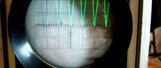
Our tests at 500 - 1000 VDC and short-circuit current values of 1000 - 7000 A used a 20 MVA test cell. A special test board was created to trigger the pyroelectric switch. This board consisted of capacitors that provided a charge of 8 A, and a trigger when the opening command was given. At this current level, the pyroelectric switch cut the copper rod in 300 μs. Figure 7 shows the current and voltage curves during cutting for a short-circuit current of 7,000 A at 1,000 VDC. The total short circuit tripping time is 1.5 ms. During the opening process, an overvoltage due to an arc in the parallel fuse can be observed. This voltage surge can be reduced by replacing the fuse with another fuse with a different element (11). In this test, the parallel fuse had a range of 63 A, so the minimum short-circuit current that the system could clear in 50 ms was 400 A. The total short-circuit clearing time consisted of three stages, as described in (1):
Total short circuit tripping time = igniter + melting of the fuse link + arcing in the fuse (1)
Figure 7: Current and voltage curves for 7,000 A fault current at 1,000 V DC
As can be seen, the total short-circuit tripping time can be calculated by adding the values of the ignition time (independent of the short-circuit current, but depending on the igniter current), the melting time of the fuse link and the arc formation time (depending on the short-circuit current). Figure 8 shows the total fault clearing time as a function of the RMS current and the excessive load the system can withstand. The short-circuit tripping time for a pyroelectric fuse is selective because it is almost independent of the short-circuit current. In fact, between 400 A and 600 A, the device protects the application in less than 50 ms, and above 600 A, within 3 ms. Moreover, the pyroelectric fuse can withstand excessive load without deterioration (curve AA'). For example, an excessive load of 7,000 A may flow through the device for 100 ms. These characteristics make the pyroelectric fuse a taxable product with the ability to adjust the time-current curve, which is not typical for a traditional fuse.
The following section presents the pros and cons of a pyroelectric fuse compared to traditional fuses.
C. Comparison between pyroelectric and traditional fuses
As AC applications continue to grow at moderate steps, facing rapidly increasing demand for DC protection devices (12), dealing with rapidly developing markets such as electric vehicles/hybrid electric vehicles, battery energy storage, data center , photovoltaic installations, electric propulsion or aircraft with electrified equipment. To respond to demand, we have developed a complete range of overcurrent protection devices. Among them you can find fuses and pyroelectric fuses. This chapter presents a comparison between the two technologies.
Figure 8: Total circuit interruption time and overload current
First let's focus on the benefits of this solution. Today's DC fuses are ultra-fast fuses designed for high short-circuit currents with cost-effective and proven technology. The pyroelectric fuse is a fast-acting protection with cost-effective technology. Conduction losses are almost zero and the system works for both low and high fault currents (in maximum configuration). Table 2 presents the functional characteristics of various technologies. Both products are not recyclable as they are used as maximum protection. When using a pyroelectric fuse, the short-circuit tripping time is independent of current, and the time-current curve can be fully adjusted, which is not the case with a traditional fuse. The new solution has excellent cycling performance with low dielectric losses.
| Characteristic | DC fuse | Pyroelectric switch + fuse |
| Recyclable | No | No |
| Switch-off time for high short-circuit current | Excellent, 10 µs | Okay, 1 ms |
| Switch-off time of weak short-circuit current | Slow melting | Great |
| Cyclicity indicators | Limited | Great |
| Dielectric conduction losses | 80 W (400 A) | 20 W (400 A) |
| Setting the time-current curve | Limited | Yes |
| Autonomous energy source | Yes | Maybe |
| Average market price | Low | Low |
Table 2: Comparative performance of pyroelectric and traditional fuses
The new overcurrent protection device has many advantages, but the main problem is the electronic control. In fact, this solution does not have an independent energy source like a fuse, so it needs to add a current sensor and an electronic system. In some applications it is not possible to install such an electronic system to the required extent. For these reasons, a self-actuating pyroelectric fuse was developed. The next chapter will introduce the principle and characteristics of maximum protection.