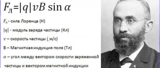
Definition The Lorentz force is a force acting on a moving charged particle from a magnetic field.
The Lorentz force modulus is denoted as FL. The unit of measurement is Newton (N).
The Lorentz force modulus is numerically equal to the ratio of the force modulus F acting on a section of a conductor of length l to the number N of charged particles moving in an orderly manner on this section of the conductor:
FL=FN.
Let's consider a section of a thin straight conductor carrying current. Let the length of the segment ∆l and the cross-sectional area of the conductor S be so small that the magnetic field induction vector →B can be considered unchanged within this segment of the conductor.
The current strength I in a conductor is related to the particle charge q, the concentration of charged particles (the number of charges per unit volume) and the speed of their ordered movement v by the following formula:
I=qnvS
The magnitude of the force acting from the magnetic field on the selected current elements is equal to:
F=|I|ΔlBsin.α
Substituting here the expression obtained for the current strength, we get:
F=|qnvS|ΔlBsin.α=|q|nvSΔlBsin.α
Let us take into account that the number of charged particles in the volume under consideration is equal to the product of the value of this volume and the concentration of the particles themselves:
N=nSΔlB
Then:
F=|q|vNBsin.α
Consequently, each moving charge is acted upon by a Lorentz force equal to:
FL=FN..=|q|vNBsin.αN..=|q|vBsin.α
α is the angle between the velocity vector of a moving charge and the magnetic induction vector.
Example No. 1. Determine the force acting on a charge of 0.005 C moving in a magnetic field with an induction of 0.3 T at a speed of 200 m/s at an angle of 45o to the magnetic induction vector.
FL=|q|vBsin.α=0.005·200·0.3·√22..≈0.2 (N)
Definition and formula of Lorentz force
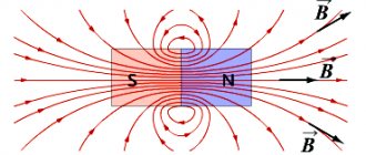
At school they often show an experiment with a magnet and iron filings on a paper sheet. If you place it under the paper and shake it slightly, the sawdust will line up along lines that are commonly called lines of magnetic intensity. In simple terms, it is the force field of a magnet that surrounds it like a cocoon. It is closed on itself, that is, it has neither beginning nor end. This is a vector quantity that is directed from the south pole of the magnet to the north.
If a charged particle were to fly into it, the field would affect it in a very curious way. She wouldn't slow down or speed up, but would just veer to the side. The faster she is and the stronger the field, the more this force acts on her. It was called the Lorentz force in honor of the physicist who first discovered this property of the magnetic field.
It is calculated using a special formula:
FL=qvB,
here q is the magnitude of the charge in Coulombs, v is the speed at which the charge moves, in m/s, and B is the magnetic field induction in the unit of measurement T (Tesla).
Useful information and tips
- It is generally accepted that the direction of current points from plus to minus. In fact, in a conductor, the orderly movement of electrons is directed from the negative pole to the positive pole. Therefore, if you were faced with the task of calculating the Lorentz force for an individual electron in a conductor, you should take this circumstance into account.
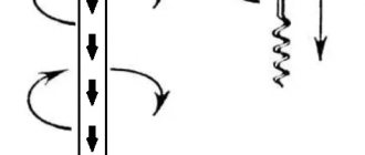
- By default, we consider a screw (gimlet, corkscrew) with a right-hand thread. However, we should not forget about the existence of screws with left-hand threads.
- When using the clockwise rule, we assume that the arrows move from left to right. It is known that in the former USSR watches with a reverse movement of the clock mechanism were produced. Perhaps such models exist to this day.
It is useful to know that when the gimlet rotates along the direction of rotation of the body, the trajectory of its screwing in will coincide with the direction of the angular velocity.
- https://odinelectric.ru/knowledgebase/sila-lorenca-i-pravilo-levoj-ruki-dvizhenie-zarjazhennyh-chastic-v-magnitnom-pole
- https://intech-irk.ru/tehnika/pravilo-pravoj-ruki.html
- https://www.asutpp.ru/pravilo-buravchika-prostym-yazykom.html
- https://electric-220.ru/pravilo-levoj-ruki
- https://seti.guru/pravilo-pravoy-i-levoy-ruki-v-fizike-primenenie
Lorentz force direction
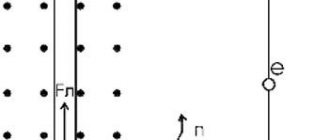
Scientists have noticed that there is a certain pattern between the way a particle flies into a magnetic field and where it deflects it. To make it easier to remember, they developed a special mnemonic rule. Memorizing it requires very little effort, because it uses what is always at hand - your hand. More precisely, the left palm, after which it is called the left hand rule.
So, the palm should be open, four fingers pointing forward, the thumb protruding to the side. The angle between them is 900. Now you need to imagine that the magnetic flux is an arrow that digs into the palm from the inside and comes out from the back. At the same time, the fingers look in the same direction as the imaginary particle is flying. In this case, the thumb will show where it will deviate.
Interesting!
It is important to note that the left-hand rule only applies to particles with a plus sign. To find out where the negative charge will deviate, you need to point four fingers in the direction from which the particle is flying. All other manipulations remain the same.
Consequences of the properties of the Lorentz force
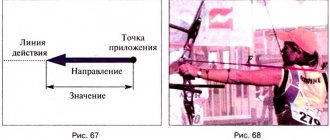
A body flies into a magnetic field at a certain angle. It is intuitively clear that its value has some significance on the nature of the field’s influence on it; a mathematical expression is needed here to make it clearer. You should know that both force and velocity are vector quantities, that is, they have a direction. The same applies to lines of magnetic intensity. Then the formula can be written as follows:
FL=qvBsinα,
sin α here is the angle between two vector quantities: the speed and flux of the magnetic field.
As you know, the sine of the zero angle is also zero. It turns out that if the trajectory of a particle passes along the magnetic field lines, then it does not deviate anywhere.
In a uniform magnetic field, the field lines have the same and constant distance from each other. Now imagine that in such a field a particle moves perpendicular to these lines. In this case, the Lawrence force will force it to move in a circle in a plane perpendicular to the lines of force. To find the radius of this circle, you need to know the mass of the particle:
R=mvqB
It is not by chance that the charge value is taken as a modulus. This means that it does not matter whether a particle enters a magnetic field negative or positive: the radius of curvature will be the same. Only the direction in which it flies will change.
In all other cases, when the charge has a certain angle α with the magnetic field, it will move along a trajectory resembling a spiral with a constant radius R and pitch h. It can be found using the formula:
R=mvsinαqB
h=2mvcosαqB
Another consequence of the properties of this phenomenon is the fact that it does not do any work. That is, it does not give or take energy from the particle, but only changes the direction of its movement.
The most striking illustration of this effect of the interaction of the magnetic field and charged particles is the northern lights. The magnetic field surrounding our planet deflects charged particles coming from the Sun. But since it is weakest at the Earth’s magnetic poles, electrically charged particles penetrate there, causing a glow in the atmosphere.
The centripetal acceleration imparted to particles is used in electrical machines - electric motors. Although it is more appropriate here to talk about the Ampere force - a particular manifestation of the Lawrence force, which acts on the conductor.
The operating principle of particle accelerators is also based on this property of the electromagnetic field. Superconducting electromagnets deflect particles from linear motion, causing them to move in circles.
The most curious thing is that the Lorentz force does not obey Newton's third law, which states that every action has its reaction. This is due to the fact that Isaac Newton believed that all interaction at any distance occurs instantly, but this is not so. It actually happens through fields. Fortunately, embarrassment was avoided, since physicists managed to rework the third law into the law of conservation of momentum, which is also true for the Lawrence effect.
Using the right hand rule in electrodynamics
If you hang a frame with current in a magnetic field on a thin and flexible wire, it will rotate and be positioned in a certain way. The behavior of a magnetic needle is similar. This indicates the vector nature of the physical quantity characterizing the magnetic field. In this case, the direction of this vector will be related to the orientation of the frame and arrow. The physical vector quantity that characterizes the magnetic field is the magnetic induction vector ($\vec{B}$).
Are you an expert in this subject area? We invite you to become the author of the Directory Working Conditions
This is one of the main parameters that describe the state of the magnetic field, so you need to be able to find its magnitude and, of course, direction.
To determine the direction of the magnetic induction vector, use:
- right screw rule or
- right hand rule.
The direction of the magnetic induction vector, at the location of the frame with current, is considered to be the direction of the positive perpendicular ($\vec{n}$) to this frame. The positive normal ($\vec{n}$) will have the same direction as the direction of translational movement of the right screw if its head is rotated along the current in the frame (Fig. 1 (a)).
Figure 1. Determination of the direction of the magnetic induction vector. Author24 - online exchange of student work
Thus, having a test frame with current, placing it in the field under study, allowing it to rotate freely in it, you can determine the direction of the magnetic induction vector at each point in the field. You just need to let the frame come to a balanced position, then use the right screw rule.
Finished works on a similar topic
Course work Rule of the left and right hand for a magnetic field 490 ₽ Abstract Rule of the left and right hand for a magnetic field 270 ₽ Test paper Rule of the left and right hand for a magnetic field 200 ₽
Receive completed work or specialist advice on your educational project Find out the cost
Now let's look at the right hand rule. Let's clench our right hand into a loose fist (Fig. 2). Bend your thumb 90°. Let's place the hand so that the thumb indicates the direction of current flow, then the bent other four fingers will indicate the direction of the lines of magnetic induction of the field that creates the current. And we remember that the tangent at each point of the field to the field line (magnetic induction line) indicates the direction $\vec{B}$.
Figure 2. Right hand rule. Author24 - online exchange of student work
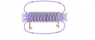
Let's consider a solenoid. Let's clasp it with our right palm so that four fingers coincide with the direction of the current in it, then the finger bent ninety degrees will indicate the direction of the magnetic field created inside it.
We know that if a conductor is moved in a magnetic field, an induction current will arise in this conductor. The right hand rule can be used to determine the direction of flow of induced current in such conductors. Wherein:
- the magnetic field induction lines should enter the open palm of the right hand,
- bend the finger of this hand ninety degrees and direct it according to the speed of movement of the conductor,
- the extended four fingers will indicate the direction of the induction current.
The right-hand rule can be used to determine the direction of the induced emf in a circuit:
With the bent four fingers of your right hand, grasp the contour in which the EMF is induced when the magnetic flux changes, bend the thumb of this hand ninety degrees and direct it in the direction of the magnetic flux when it increases (or against the direction of the magnetic flux when it decreases), then the bent fingers will point in the direction opposite to the EMF.
Concept of electric field strength
The electromagnetic field actually consists of two halves - electric and magnetic. They are like twins, with everything the same, but with different personalities. And if you look closely, you can notice slight differences in appearance.
The same goes for force fields. The electric field also has intensity - a vector quantity, which is a force characteristic. It affects the particles that are motionless in it. In itself, it is not a Lorentz force; it simply needs to be taken into account when calculating the effect on a particle in the presence of electric and magnetic fields.
A magnetic field
In accordance with the above, we can give the following definition of a magnetic field.
A magnetic field is one of the two sides of the electromagnetic field, excited by the electric charges of moving particles and changes in the electric field and characterized by a force effect on moving infected particles, and therefore on electric currents.
| Figure 1. Magnetic field around a current-carrying conductor |
| Figure 2. Direction of magnetic induction lines |
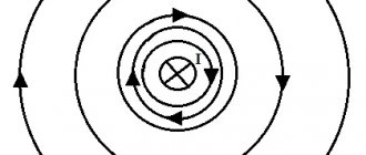
If you pass a thick conductor through cardboard and pass an electric current through it, then the steel filings poured onto the cardboard will be located around the conductor in concentric circles, which in this case are the so-called magnetic induction lines (Figure 1). We can move the cardboard up or down the conductor, but the location of the steel filings will not change. Consequently, a magnetic field arises around the conductor along its entire length.
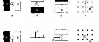
If you put small magnetic arrows on the cardboard, then by changing the direction of the current in the conductor, you can see that the magnetic arrows will rotate (Figure 2). This shows that the direction of magnetic induction lines changes with the direction of current in the conductor.
Magnetic induction lines around a current-carrying conductor have the following properties: 1) magnetic induction lines of a straight conductor have the shape of concentric circles; 2) the closer to the conductor, the denser the magnetic induction lines are located; 3) magnetic induction (field intensity) depends on the magnitude of the current in the conductor; 4) the direction of magnetic induction lines depends on the direction of the current in the conductor.
To show the direction of the current in the conductor shown in section, a symbol has been adopted, which we will use in the future. If you mentally place an arrow in the conductor in the direction of the current (Figure 3), then in the conductor in which the current is directed away from us, we will see the tail of the arrow’s feathers (a cross); if the current is directed towards us, we will see the tip of an arrow (point).
Figure 3. Symbol for the direction of current in conductors
Task examples
Problem 1
A charge of 0.005 C, which moves in a magnetic field with an induction of 0.3 T, is subject to the Lorentz force. Calculate it if the speed of the charge is 200 m/s, and it moves at an angle of 450 to the lines of magnetic induction.
| Given: q = 0.005 C B = 0.3 T v = 200 m/s α = 450 | Solution: In the conditions of the problem there is no mention of the electric field, so the Lorentz force can be found using the following formula: FL=qvBsinα=0.005×200×0.3×sin 450 =0.3×22=0.21 N |
Problem 2
Determine the speed of a body that has a charge and which moves in a magnetic field with an induction of 2 T at an angle of 900. The magnitude with which the field acts on the body is 32 N, the charge of the body is 5 × 10⁻³ C.
| Given: q = 0.005 C B = 2 T FL = 32 N α = 900 | Solution: To find the charge speed, it is necessary to slightly modify the formula for finding the Lorentz force: FL=qvBsinαv=FLqBsinα v=320.005×2×sin900=320.01×1=32000ms=32 km/s |