A magnetic field
Already in the 6th century. BC. In China, it was known that some ores have the ability to attract each other and attract iron objects. Pieces of such ores were found near the city of Magnesia in Asia Minor, so they were called magnets
.
How do magnets and iron objects interact? Let's remember why electrified bodies are attracted? Because a peculiar form of matter is formed near an electric charge - an electric field. There is a similar form of matter around the magnet, but it has a different nature of origin (after all, the ore is electrically neutral), it is called a magnetic field
.
To study the magnetic field, straight or horseshoe magnets are used. Certain places of a magnet have the greatest attractive effect; they are called poles
(north and south)
. Opposite magnetic poles attract, and like magnetic poles repel.
For the strength characteristics of the magnetic field, use the magnetic field induction vector B
.
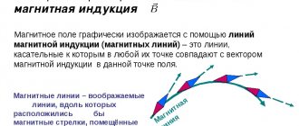
The magnetic field is graphically represented using lines of force ( magnetic induction lines
). Lines are closed, have neither beginning nor end. The place from which magnetic lines emerge is the North Pole; magnetic lines enter the South Pole.
The magnetic field can be made “visible” using iron filings.
The direction of the current and its magnetic field lines. Gimlet rule
Ampere's research...
belong to the most
brilliant works that
ever carried out in science.
James Clerk Maxwell
A magnetic field
is a force field acting on moving electric charges.
To visually represent the magnetic field, magnetic lines are used Magnetic lines
- these are imaginary lines along which small magnetic arrows would be located, placed in a magnetic field.
The closure of magnetic field lines is a fundamental property of the magnetic field.
It indicates that
magnetic charges
similar to electric ones
in nature
.
The direction of the magnetic line at any point is conventionally taken to be the direction indicated by the north pole of the magnetic needle placed at this point.
Now let’s look at what the direction of the current magnetic field lines depends on in more detail.
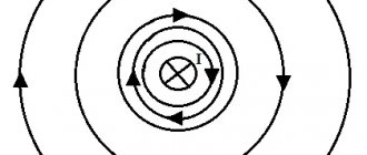
It is known that to obtain the spectrum of the magnetic field of a straight conductor carrying current, it can be passed through a sheet of cardboard, and iron filings can be poured onto the cardboard. Under the influence of a magnetic field, iron filings are arranged in concentric circles. Let's place magnetic arrows along the magnetic field lines.
The figure shows the location of magnetic needles around a current-carrying conductor perpendicular to the plane of the drawing. If you change the direction of the current in the conductor, you can see that changing the direction of the current leads to a rotation of all magnetic arrows by 1800. Moreover, the axes of the arrows are located tangent to the magnetic lines
.
That. we can conclude that the direction of the magnetic field lines will depend on the direction of the current in the conductor
.
This relationship can be expressed by a simple rule called the gimlet rule (or right screw rule).
The gimlet rule is as follows:
If you turn the head of the screw so that the translational movement of the tip of the screw occurs along the current in the conductor, then the direction of rotation of the head indicates the direction of the magnetic field lines of the current.
Using the gimlet rule, in the direction of the current, you can determine the direction of the magnetic field lines created by this current, and in the direction of the magnetic field lines, you can determine the direction of the current creating this field.
To determine the direction of the magnetic field lines of the solenoid, it is more convenient to use another rule, which is sometimes called the right-hand rule
.
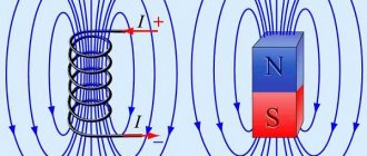
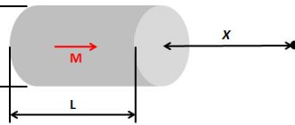
Solenoid
is a cylindrical coil of wire, the turns of which are wound close to each other in one direction, and the length of the coil is significantly greater than the radius of the turn.
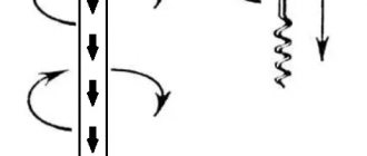
The magnetic field of a solenoid can be represented as the result of the addition of fields created by several circular currents having a common axis.
The figure shows that inside the solenoid, the magnetic field lines of each individual turn have the same direction, while between adjacent turns they have the opposite direction. Therefore, with a sufficiently dense winding of the solenoid, the oppositely directed sections of the magnetic field lines of neighboring turns will be mutually destroyed, and the equally directed sections will merge into a common line.
The study of this field using iron filings showed that inside the solenoid the magnetic field lines are straight, parallel to the axis of the solenoid, which diverge at its ends and close outside the solenoid
.
Knowing the direction of the current in the coil, the poles of the solenoid can be determined using the right-hand rule
: if you clasp the solenoid with the palm of your right hand, pointing four fingers in the direction of the current in the turns, then the extended thumb will show the direction of the magnetic field lines inside the solenoid.
The right-hand rule can also be used to determine the direction of the magnetic field lines in the center of a single current-carrying coil.
From the 8th grade physics course it is known that for any current-carrying conductor placed in a magnetic field and not coinciding with its magnetic lines, this field acts with some force.
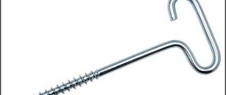
The presence of such force can be demonstrated by installation. The three-sided wire frame ABCD is suspended on hooks so that it can freely deviate from the vertical.
The BC side is located in the region of the strongest field of the arc-shaped magnet, located between its poles. The frame is connected to the current source in series with a rheostat and a key. When the key is closed, an electric current arises in the circuit, and the BC side is drawn into the space between the poles.
If you remove the magnet, then when the circuit is closed, the conductor BC will not move. This means that from the side of the magnetic field, a certain force acts on the current-carrying conductor, deflecting it from its original position.
Thus, a magnetic field is created by an electric current and is detected by its effect on the electric current
.
If you change the direction of the current in the circuit by swapping the wires in the sockets of the insulating stand, then the direction of movement of the conductor will also change, and therefore the direction of the force acting on it.
The direction of the force will also change if, without changing the direction of the current, the poles of the magnet are swapped (that is, the direction of the magnetic field lines is changed).
Consequently, the direction of the current in the conductor, the direction of the magnetic field lines and the direction of the force acting on the conductor are interconnected.
The direction of the force acting on a current-carrying conductor in a magnetic field can be determined using the left-hand rule
, which is as follows: if the left hand is positioned so that the magnetic field lines enter the palm perpendicular to it, and the four extended fingers are directed along the current, then the thumb set at 90° will show the direction of the force acting on the conductor.
Using the left-hand rule, it should be remembered that the direction of the current in the outer part of the electrical circuit
(i.e. outside the current source)
is taken from the positive pole of the current source to the negative
. In other words, the four fingers of the left hand should be directed against the flow of electrons in the electrical circuit.
Using the left hand rule
it is possible to determine the direction
of the force with which the magnetic field acts on an individual particle moving in it
, both positively and negatively charged.
For the simplest case, when a particle moves in a plane perpendicular to the magnetic lines, this rule is formulated as follows
: if the left hand is positioned so that the magnetic field lines enter the palm perpendicular to it, and four fingers are directed along the movement of the positively charged particle (or against the movement of the negatively charged one), then the thumb placed at 90° will show the direction of the force acting on the particle.
It should be noted that the force of a magnetic field on a current-carrying conductor or a moving charged particle is zero if the direction of the current in the conductor or the speed of the particle coincides with the magnetic induction line or is parallel to it.
Main conclusions:
– The direction of the magnetic field lines will depend on the direction of the current in the conductor.
– This relationship can be expressed using the gimlet rule
(or
rules of the right screw
): if you turn the head of the screw so that the translational movement of the tip of the screw occurs along the current in the conductor, then the direction of rotation of the head indicates the direction of the magnetic field lines of the current.
– To determine the direction of the magnetic field lines of the solenoid
It’s more convenient to use
the right hand rule
: if you clasp the solenoid with the palm of your right hand, pointing four fingers in the direction of the current in the turns, then the extended thumb will show the direction of the magnetic field lines inside the solenoid.
– A magnetic field acts with some force on any current-carrying conductor located in this field.
The direction of this force can be determined using the left-hand rule: if the left hand is positioned so that the magnetic field lines enter the palm perpendicular to it, and the four extended fingers are directed along the current, then the thumb set at 90° will show the direction of the force acting on the conductor .
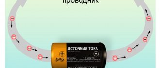
Magnetic field of a current-carrying conductor
And now about what Hans Christian Oersted
and
André Marie Ampère
in 1820. It turns out that a magnetic field exists not only around a magnet, but also around any current-carrying conductor. Any wire, such as a lamp cord, through which electric current flows is a magnet! A wire with current interacts with a magnet (try holding a compass near it), two wires with current interact with each other.
Direct current magnetic field lines are circles around a conductor.
Determining the shape of the magnetic field
What does a magnetic field “look” like? Let's do a simple experiment (Figure 1).
We have a straight conductor carrying current. Let's make a hole in a sheet of cardboard and thread our conductor through it. Place a thin layer of iron filings on the cardboard and turn on the current.
What will we see? How are the iron filings now located in a direct current magnetic field?
Figure 1. Arrangement of iron filings in a direct current magnetic field
Under the influence of a magnetic field, the sawdust will take an interesting position. They no longer lie randomly on a sheet of cardboard, but are located around the conductor in concentric circles.
Magnetic induction vector direction
The direction of the magnetic field at a given point can be defined as the direction indicated by the north pole of a compass needle placed at that point.
The direction of the magnetic induction lines depends on the direction of the current in the conductor.
The direction of the induction vector is determined using the gimlet
or
right hand
.
How to determine linear magnetic directivity
To determine where the lines in question are directed, you can use various available methods. How to determine the direction of magnetic lines will be discussed in more detail below.
Gimlet rule
The most common method for determining the path of the lines under consideration is the gimlet rule. People first started talking about it back in the 19th century, when scientists discovered a magnetic field around a conductor connected to voltage.
The lines of force that are formed have a similar behavior to a natural magnet. In addition, the connection between the conductive electric field and the MF current has become the primary source of the dynamics of electromagnets.
Also, when determining the location, you can find the following axial-vector indicators:
- magnetic induction;
- size and path of induction current;
- angular velocity.
If you combine the continuous movement of the gimlet on the right side with the path of the conductive current, it will be possible to determine the direction of the lines, which is indicated by the path of movement of the handle.
This rule is not generally recognized, since, in fact, it does not apply to known physical laws. It is used to determine not only the path of the power lines under consideration, depending on the path of current movement. It can also be used to detect the direction of current in solenoid wires when the flux lines begin to move.
When Ampere identified such a connection, he was able to explain the law of fields that rotate. This led to the creation of various electric motors. All retractor-type equipment uses an inductive coil, which works according to the gimlet rule.
"Right Hand Rule"
The determination occurs without the use of instruments, but only by hand. If you turn your palm towards the pole from the North, and deflect your thumb at a right angle, it will show the path of the conductor's direction. This will lead to the fact that in a closed loop the magnetic field will cause electricity, and four fingers will show the vector of current movement.
This rule determines exactly how DC generators were created. A natural phenomenon (windy weather or strong flow of water) rotates a loop of closed conductors in a magnetic field, which leads to the generation of energy.
Afterwards, the engines that received electric current changed it to mechanical movement.
"Left hand rule"
Another popular method, but using the other hand. Some people mistakenly equate it with the first rule. First you need to straighten your left palm and place it along the conductor. The fingers will show which way the current flows. The MP lines will pass through the open palm. The thumb repeats the force vector. This is the basic meaning of the left hand rule. The above force vector is the Ampere force.
As you can see, there is nothing difficult in determining the direction of magnetic field induction. The main thing is to remember what the school physics curriculum was about. You do not need additional instruments to measure the directions of magnetic field lines.
It is enough to use the gimlet rule or the one-hand method.
Magnetic induction vector
This is a vector quantity characterizing the force action of the field.
Induction of the magnetic field of an infinite straight conductor with current at a distance r from it:
Magnetic field induction at the center of a thin circular coil of radius r:
Solenoid magnetic field induction
(a coil whose turns are sequentially passed current in one direction):
Relationship between the directions of magnetic lines and the direction of electric current
Magnetic lines give us the opportunity to depict the magnetic field graphically.
At what distance from the conductor can we draw its magnetic lines? The answer is simple - for a graphic image we can use a scale that is convenient for us.
A magnetic field exists at all points in space surrounding a current-carrying conductor. This means that we can legally draw a magnetic line through any point.
Okay, but how to determine the direction of magnetic lines? Experiments show the following:
The direction of the magnetic lines of the magnetic field of the current is related to the direction of the current in the conductor.
Since magnetic lines lie in a plane perpendicular to the current-carrying conductor, it is customary to depict a cross-section of a conductor in drawings (a cross-section of a conductor). The direction of the current is conventionally indicated by a cross if the current is directed away from us, and a dot if the current is directed towards us (Figure 3).
Figure 3. Current direction symbols
Take a look at Figure 4, a. Current flows down the conductor. Magnetic needles are installed along magnetic lines. Their axes are oriented as shown in the figure.
Figure 4. Direction of magnetic lines when current moves down/away from us
A graphical representation of such a magnetic field is presented in Figure 4, b. The conductor carrying current is located perpendicular to the plane of the drawing, as if we were looking at it from above, and not from the side. We marked the direction of the current with a cross on the conductor itself (away from us), and indicated the direction of the magnetic lines (where the north poles of the magnetic needles point.
Now we’ll make sure that the current goes up, not down. What will we see? The magnetic needles are again located along the circle, but the orientation of their axes has changed (Figure 5, a). Now they have turned around by $180 \degree$ compared to the first situation, where the current was flowing down the conductor.
Figure 5. Direction of magnetic lines when current moves up/towards us
Figure 5, b shows a graphical representation of such a field. The fact that the current is directed towards us is conventionally indicated by a point on the conductor. The direction of the magnetic lines has changed to the opposite.
Such a simple experiment confirmed to us the fact that the direction of magnetic lines is related to the direction of the current.
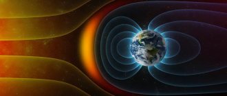
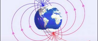
Earth's magnetic field
The Earth is not only a large negative charge and a source of electric field, but at the same time the magnetic field of our planet is similar to the field of a direct magnet of gigantic proportions.
Geographic south is close to magnetic north, and geographic north is close to magnetic south. If a compass is placed in the Earth's magnetic field, then its north arrow is oriented along the lines of magnetic induction in the direction of the south magnetic pole, that is, it will show us where the geographic north is located.
The characteristic elements of the earth's magnetism change very slowly over time - secular changes
. However, from time to time magnetic storms occur, when the Earth's magnetic field is greatly distorted for several hours and then gradually returns to its previous values. Such a drastic change affects people's well-being.
The Earth's magnetic field is a “shield” that protects our planet from particles penetrating from space (“solar wind”). Near the magnetic poles, particle flows come much closer to the Earth's surface. During powerful solar flares, the magnetosphere is deformed, and these particles can move into the upper layers of the atmosphere, where they collide with gas molecules, forming auroras.
Definition
In a narrow sense, the gimlet rule is a mnemonic algorithm used to determine the spatial direction of magnetic induction, depending on the orientation of the electric current exciting the magnetic field.
This rule can be formulated as follows: If the tip of a gimlet (corkscrew, screw) is directed along the current vector, then the orientation of the magnetic induction lines will coincide with the direction towards which the handle of the gimlet rotates in the traditional version of this tool (with a right-handed screw) [1] (Fig. . 1.)
Rice. 1. Gimlet rule for a straight conductor
Figure 1 shows a diagram for the simplest case: an electric current flows along a straight section of a conductor, away from the observer (blue arrow). The conditional corkscrew is directed with its sharp end along the line in the direction of the current. If we imagine the translational movement of a gimlet along a conductor, then the direction of the lines described by the handle of the corkscrew will coincide with the orientation of the magnetic lines of the electric field.
Right hand rule
In electrical engineering, the interpretation of the gimlet for the right hand is often used.
The actions can be formulated as follows: “If the thumb of the right hand, set aside, is placed along the conductor so that it coincides with the direction of the electric current, then the remaining fingers will indicate the direction of the magnetic lines of force formed by the electric field. (see diagram in Fig. 2).
Rice. 2. Illustration of the right hand rule
The algorithms formulated above are also applied to solenoids. But the difference is that in the case of a solenoid, the gimlet handle is rotated so that this movement coincides with the direction of the currents in the turns, and the advancement of the gimlet screw indicates the orientation of the vector of magnetic lines in the solenoid.
When using the right hand, fingers cover (conditionally) the coil so that the direction of the current in the turns coincides with the spatial arrangement of the fingers. Then the thumb will point to the orientation of the vector of electromagnetic lines inside the coil. Figure 3 shows diagrams explaining algorithms for determining the directions of vectors for solenoids.
Rice. 3. Illustration of the right hand rule for a reel
It is not difficult to guess that these rules can be applied to determine the direction of the current. For example, if you use a magnetic needle to determine the direction of magnetic induction lines, then by applying the gimlet rule (as a variant of its formulation for the right hand), it is easy to determine in which direction the current flows.