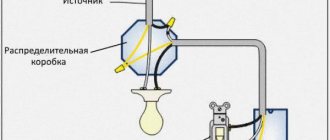
Control circuits
Electromagnetic contactors do not have mechanical locking in the on position. To ensure that the rod is held during operation, a self-retaining circuit is used. This is a fairly convenient technique that allows you to switch the coil power circuit with various protection and automation devices of the electric drive. The exception is assemblies controlled by PLC or relay automation.
The simplest self-retaining circuit includes one additional blocking normally open contact. The coil power circuit is connected through a normally open contact of the start button. The second circuit is connected in parallel; it consists of a series-connected blocking contact and a normally closed contact of the “Stop” button. Thus, when the contactor is turned on, a blocking contact is closed, which is held during operation and supplies power to the coil. If it is necessary to stop, the coil power circuit is opened with the “Stop” button.
Contactor self-retaining circuit: L1, L2, L3 - three-phase power supply phases; N - neutral; KM - magnetic starter coil; NO13-NO14 - additional normally open contact; M - asynchronous motor
There are also more complex control schemes
Thus, the use of a normally closed contact of the start button of one contactor can be used to prevent the simultaneous operation of two starters, which, in particular, may be important when constructing reversing circuits or may be due to other technological needs. The same principle can operate when using a normally closed blocking contact of one contactor, which is connected in series with the start button contact of another.
Scheme of reverse engine starting: KM1, KM2 - coils of magnetic starters; NO KM1, NO KM2 - normally open contacts of starters; NC KM1, NC KM2 - normally closed contacts of starters; KK - thermal relay
The self-retaining circuit can also include limit switches, dry contact sensors and various protective devices. Automatic activation of the contactor is also possible; for these purposes, the button is replaced or duplicated by parallel activation of limit switches or sensors. Thus, the complexity and control schemes of an automated electric drive are practically unlimited.
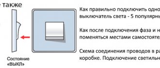
Connection diagram for PV cables in the distribution box
Changeover switch installation diagrams
An important step is assembling the pass-through switch circuit in the distribution box. 4 wires with 3 cores go to it - a power cable from the automatic light control from the switchboard, a cable to the 1st and 2nd switch, a cable to the light source.
During the work you need to focus on the color of the wire:
- phase – white/gray;
- zero – blue/brown;
- earth – yellow-green/black.
The assembly provides the following step-by-step algorithm:
- Connection of the neutral core coming from the input cable of the machine and the neutral wire going to the lamp with terminals.
- Connecting all earth conductors in the presence of a grounding conductor. The ground from the input is thrown onto the outlet ground using terminals.
- Ground connection to the housing of the lighting device.
- Coupling the phase from the input cable with the phase from the outgoing cable and fastening them to a common terminal in the 1st switch.
- Connection of the common wire of the 2nd switch with the phase of the lighting cable terminal.
- Connection of secondary outgoing conductors of switches No. 1 and No. 2.
- Applying voltage and testing the design.
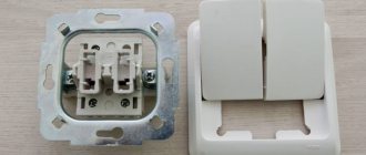
Design and principle of operation of a two-key switch
The design of the two-key switch is quite simple. It consists of:
- Two keys (moving parts up and down).
- Housing (shell), which is removed before starting work with electricity.
- Terminal blocks (those places to which voltage or current is supplied).
Switch design
In rare cases, the third element - terminal blocks - can be replaced in the design with screw terminals. The difference is that the former hold the wire for a long time and securely, and the latter do the same, but without pinching the wire, twisting it, so the first option is easier to connect and lasts longer. The design may also include additional lighting - a dimmer located on each key.
Inside the two-key switch without backlight there are two wires running parallel to each other + an input for the phase. Each of the terminals suitable for the keys can independently open or close a contact that turns on one lamp, a second lamp, or all lamps at once.
Two-gang switch wires
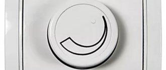
The principle of operation of the switch is to vary the degree of illumination:
- You can turn on only one key so that one light bulb (or the first group of lights) lights up.
- It is possible to turn on the second key - the lighting will change, since some parts of the room will be clearly visible, while others will be slightly darkened.
- The third option is to turn on all the lamps at once - both keys are in the “on” position - then the room receives maximum illumination.
Some two-gang switches consist of two single-gang devices isolated from each other. In this case, it is customary to call them modular.
In addition to the external component, such a device can also perform the functions of saving energy and creating a varied atmosphere. Two-button switches also increase safety, since when they are installed in a room, the number of points with electrical voltage is reduced.
Before starting work on preparing to connect the switch, we suggest that you familiarize yourself with the diagram of the two-key switch below:
Choosing a location to install the master button
In most cases, it is installed in the hallway or corridor, in the hall or at the reception, or at the security console. But if you use a standard switch, it can be confused with the one that should turn on the light in the room. Therefore, to avoid confusion, the master button can be mounted at a different height. You can also use special switches with a cover that prevents accidental pressing.
One object can have several master buttons at the same time, working synchronously or separately. A synchronous connection diagram will be convenient if there are several outputs (main and service, front and black). Then you can turn on or off the light on the object from any of them. A separate connection scheme is often used for different floors and workshops that are only indirectly connected to each other.
What is a master switch
Modular contactor
The contactor is a modular element mounted on a DIN rail and provides convenient load switching in a home electrical system. Its performance characteristics also depend on the selected contactor. For example, if a master switch with four groups of contacts is installed, the maximum permissible switching power of each of them will be around 24 amperes. In the vast majority of cases, such a switch is enough to turn off the electricity in your apartment or country house without any problems.
If the room uses single-phase power with a power of up to 20 amperes, it will be quite enough to install a two-pole contactor.
The simplest option for controlling a contactor is to use a main disconnecting device, which will be located indoors. This device looks like an ordinary switch that operates in two positions - “on” and “off”. When turned off, the light immediately disappears in the entire room, regardless of the position of the other switches, while when the system is turned back on, the light will appear only where it was turned on.
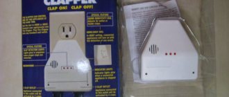
Card light switch
Exactly the same as in hotels it is necessary to turn on and off all the lights and sockets.
Any card of a suitable format is inserted into it. The card simply presses a button inside the device. Such a device costs from 500 rubles, it is stared into an ordinary socket box. An advantage from the previous option is that you won’t press it accidentally.
Disadvantages: firstly, absolutely any card will do, and secondly, you need to put this card nearby (it will get lost) or carry it with you. Well, it’s not so beautiful, the house is still not a hotel.
Using thermal relays with magnetic starters
The possibility of triggering the thermal relay (1) is provided in case of an emergency. The circuit contact (4) is broken, followed by disconnection of the coil and return of the core to its original state by special return springs. After disconnecting the contacts in this way, the dangerous voltage is removed in the emergency area.
Connecting a magnetic starter together with a thermal relay provides reliable protection of electrical units from possible overloads. These devices serve as an effective addition to automatic machines, the bimetallic strips of which cannot always protect during an accident. Although, the principle of operation of a thermal relay is the same as that of the thermal element of an automatic protective switch. However, the thermal relay does not automatically switch off, but only sends a set signal to perform this operation. It must be accurately and competently recognized, and put into practice in a timely manner.
A thermal relay equipped with power contacts can be directly connected to a magnetic starter without the use of conductors. However, products from different manufacturers may not match, fit or interact with each other.
Each thermal relay is equipped with two groups of contacts, independent of each other - normally closed and normally open. To break the circuit, a closed contact is used, operating through the STOP button. All working contacts are present in the circuit intended for control. They are connected directly next to the coil, but can be placed in other convenient places.
The actuation process of the thermal relay is completely invisible from the outside. Returning to the original state is carried out using a small button located on the panel. You do not need to transfer the contacts immediately, but only after the relay has cooled down, otherwise they will not be securely fixed. Before the very first use, it is recommended to press the button to avoid careless switching during transportation.
Advantages of using a 24V contactor
Switching high currents and powers
Using a contactor or starter allows you to safely connect powerful equipment with high starting currents, for example, electric motors.
Conditional safe voltage
Since a 24V contactor is used, the corresponding AC voltage from the transformer is also supplied to the switching device, which is much safer during operation.
Possibility of using both normally closed and open contacts
Depending on the contactor model, any type of signal produced by dry contacts can be used equally successfully: their opening, closing, or both at once.
Ability to work with three-phase consumers
There are models of contactors designed to power both single- and three-phase equipment.
Automatic power recovery
As soon as the dry contact returns to its nominal state, the contactor immediately restores power to the equipment connected to it; this is the operating mode that is most often in demand.
Contactless key reader
This option is much more convenient and reliable.
Probably everyone has a drop key on their keys for a gate or intercom:
On the wall we will need to place a key reader with a built-in controller, for example, Matrix IIK
From the outside it looks like a white rectangle with a small LED. You need to supply 12V power to it; there is a relay on the board. There are two operating modes: sending a short pulse when a programmed key is applied, or turning the relay on/off when a key is applied. You can program all your keys. Any EmMarine format keys (drop keys) are supported, as well as contactless cards of this format. There are models that support more copy-protected, but less common Mifire cards.
Works with both contactors and pulse relays. The most interesting thing is that this reader can be hidden by completely covering it with wallpaper, for example. The reading range is about 1-2 centimeters. The main thing is not to cover it with metal elements.
That is, firstly, it can be invisible, secondly, you do not need to carry a separate key or card, and thirdly, it cannot be activated accidentally.
This reader is intended for access control systems; it has a connector for connecting an “exit button”, upon pressing which the controller will also change the state of the relay or give an impulse. You can display this button somewhere and use it as a backup option in case you lose the key.
Centralized lighting control with one button
On models with so-called central or centralized control, in addition to the above, there are additional ON and OFF terminals.
When voltage is applied to them, the relay is forced to either turn off (OFF) or turn on (ON).
They are used when assembling a circuit with a master button or master switch. That is, when leaving the house, with just one button you can centrally turn off the lights on all floors and in all rooms.
Here is a circuit assembled into several group lamps connected from different impulse relays. Please note that in this case all relays must be centrally controlled, otherwise the circuit will not work.
Scheme No. 2 - with central control
From ABB pulse generators, the central control unit can be purchased separately and connected to the left side of the E290 relay.
Just be extremely careful when assembling such a control circuit in a three-phase 380V switchboard.
If there is a three-phase system, some lighting groups are powered from different phases in order to evenly distribute the load.
In this case, it is impossible to connect all the OFF and ON contacts on the switches with jumpers, as is often done in single-phase panels. You will have to transfer all control circuits to a separate machine and it is from it that you will supply the phase of the same name to turn on and off all pulse relays simultaneously.
And then, this is possible when using electromechanical models. For electronic ones, you will have to decouple through intermediate relays.
Basics
To turn on magnetic starters and contactors, push-button posts are used. These are devices that have 2 or 3 buttons such as “Start” and “STOP” or “Forward”, “Back” and “STOP”, there are other less common options. These buttons are a non-latching button with a normally closed and normally open pair of contacts.
Starters and contactors are electromagnetic switching devices. In order for its power contacts to close, voltage must be applied to the coil. It will attract the core (anchor) on which the contacts are attached (the design may vary). When you remove the voltage from the coil, the device will turn off and its power contacts will open.
In addition to power ones, these devices have block contacts (usually several groups of them). They are not able to withstand heavy loads, but are designed to implement a self-retaining circuit and indications. The fact is that if you simply apply voltage to the coil through the push-button post, the device will turn on, but when you release the button, it will immediately turn off. This is necessary, for example, in winches and other lifting mechanisms, but not in circuits that operate for a long time without stopping, such as lights and electric motors of ventilation systems.
To avoid this, a self-retaining circuit is needed - a normally open block contact is connected in parallel with the “START” buttons on the push-button station.
Typically, such switching devices are used to connect high-power electrical appliances to the network: heating elements, motors, or, in our case, large lighting installations.
How to connect a contactor?
Contactors are switching equipment for controlling mainly three-phase motors. For contactors, the main task is to turn on, turn off and reverse at a distance, which is determined by the specific location of the motors. But motors are not the only electrical consumers with which contactors can be used. Any other types of loads can also be switched remotely using these switches. In principle, they are a structural variation of a magnetic starter.
Connection diagram for a 380 V magnetic starter
Some characteristics of magnetic starters can be seen in the table. The differences between a magnetic contactor and a starter are very conditional. First of all, it makes it easy to work with an asynchronous motor. Was this article useful to you? While some machine, such as a sawing machine, was operating, the voltage in the network was lost. I give examples of articles in which heating elements are turned on through starters: Look at the diagram for reversing the motor below: 9. Diagram for connecting a three-phase motor through a starter at B As you can see, the diagram has remained virtually unchanged. The starter coils are also switched on from the controller outputs. If this product is a circuit breaker that has thermal protection, it will trip due to heat in the frame. Reversible circuit for connecting a three-phase motor through magnetic starters To increase safety, a thermal relay has been added, through which two phases pass, the third is supplied directly, since protection in two is more than enough. And if it consists of two separate starters, a special mechanical interlock is placed between them. The organization of signal circuits is more complex. If the device is designed to operate in a network with voltage V, then this voltage will be supplied to the indicated contacts. Contactor/Magnetic starter, home use + theory. ABB ESB. Master switch
The appearance of a pass-through switch
This device has been around since time immemorial ; it used to be called a toggle switch or switch. Then someone got tired of taking extra steps, and he came up with a diagram for connecting a light bulb to two switches. It was no longer difficult to make the toggle switch look aesthetically pleasing. The name was also changed to switch. True, different manufacturers call it differently:
- checkpoint;
- transitional;
- switch.
Today the market is literally flooded with these devices, but not everyone can figure out the connection diagram.
What is a modular contactor and what is it for?
According to its functional purpose, the modular contactor KM belongs to the switching equipment for remote control of powerful loads operating at direct or alternating current. They break current circuits in several places at once, and this differs from electromagnetic relays, which break the circuit at only one point.
Quite often, modular contactors work in conjunction with auxiliary devices - set-top boxes, thermal relays, blocking devices and other modular devices. As a result of such combinations, equipment is obtained that has special properties and is capable of performing specified functions. So, when installing a delay module, you get a contactor with a delay function, and a thermal overload relay transfers the contactor to the category of a magnetic starter.
With the help of auxiliary elements, the capabilities of the main devices are significantly expanded, their performance characteristics are improved, and installation is simplified.
At their core, contactor devices are considered modified versions of a starter, which additionally contains a thermal relay and a contact group for starting the electric motor. Low voltage electromagnetic starters, reversible and non-reversible. The first option includes two identical contactors, with the same rated current. It has a mechanical or electrical interlock that prevents the main contacts from closing at the same time.
The protective functions in these devices are performed by electrothermal current relays and other similar devices. Low power electrical contactor, used as an intermediate relay. It is designed for low-current circuits and has a large number of switchings. Using this device, it is possible to connect many additional sections and control their on/off.
Contactor selection criteria
You should not choose a contactor yourself - this is a task for a highly qualified electrician who has experience working with this type of switching devices. And the difficulty here is not only in correctly calculating the parameters, but also in choosing a manufacturer.
Contactors are not cheap equipment, so often at the procurement stage the contractor or customer wants to save money. As a result, a model of a low or mid-price segment is purchased. When turned on, they make loud clicks, during operation they can buzz when the contacts stick, and their service life is lower. It is better to immediately buy a reliable contactor that will fully pay for itself during operation.
Criterias of choice:
- Rated current, voltage - the electrician calculates the parameters of the current in the switched circuit, taking into account the loads from each point of consumption, correction factors, starting surges;
- Number of poles – determines the number of phases and switched electrical circuits;
- Voltage of the electromagnetic coil - in most cases, in apartments, private houses, and offices, models with a voltage of 220V are used.
An experienced electrician takes into account some additional parameters, including the class of the contactor (the life of the switch depends on it), the degree of protection, etc.
Practical Application Examples
The digital device should be switched to dialing mode.
In this case, the same lamp can be controlled from each floor and, if desired, from the basement.
A pass-through switch allows you to close one of two circuits. How to make a pass-through switch from a regular one: work order. It is not always possible to quickly find a suitable model of a device that allows you to control lighting from two points at once. Connecting conductors using special WAGO clamps.
Let's look at the following circuit diagram: Three things have changed: From breakout box S1, switch S2 has two cables connected to it, which are used to power the other light switches. There are open type PV for connection with open wiring and closed type for connection with wiring running inside the walls. A diagram with two pass-through switches that allows control of two loads. The following video will help you understand in more detail the diagram for connecting a switch from two places: It clearly shows how to connect the wires in the junction box so that there are no difficulties during operation.
Electric lighting is an indispensable companion of any modern apartment. The first is used to connect a contact at the input, the second - at the output. To connect them, in the simplest case, you need two two-core cables. However, their functionality is very different.
Places of use In addition to the bedroom, similar situations can arise quite often. Before starting work, use a voltage tester to make sure that there is no electrical potential on the power cables, preferably on all terminals coming out of the box. The crossover device is connected between the feedthroughs. When choosing the appropriate option, you should buy a model with the same number of keys for each point. In such situations, it becomes necessary to control lighting from two places; it is for solving such problems that the so-called pass-through switches are designed.
Types of crossover and pass-through switches
With modern electrical installations, pass-through switches have become more often used, which can turn off or turn on, for example, the lighting in a room at the entrance to the room and at the same time near the bed or, for example, on both sides of the corridor. For the first case, socket boxes will be required for installation. It is also beneficial to use a similar scheme in small houses, the size of the floors. Electrical diagram for switching on a lamp from three places. An ordinary switch only closes and opens a circuit. Installing two ordinary switches in different places in the room will not allow you to control the lamp from two places at once.
Similar to switch S1, we connect the protective conductors with one connector and the neutral conductors with the help of a second connector. Conclusions and a useful video on the topic You can learn from the videos presented how the use of circuits for connecting pass-through switches from several places occurs in practice. Thanks to these jumpers, the phase to the lighting source can be supplied from either one or a second switch, which will allow you to turn on the lighting from several places. Such solutions are useful in large houses and small apartments. In order not to be mistaken about what kind of switch it is, you should familiarize yourself with the connection diagram, which is present on the switch body. Connection diagram for a two-key pass-through and crossover switch from two or more places.
Basic connection diagrams
In total, there are three power switching schemes for connecting contactors. The first and simplest is direct phase switching, which is suitable for both single-sided starting of the drive and for controlling active loads. There is nothing remarkable in the circuit; the contactor simply acts as a remote switch.
An example of using contactors in a generator autostart circuit: 1 - input circuit breaker; 2 - counter; 3 - RCD of the main network; 4 — main input contactor; 5 — automatic generator start block; 6 — gas generator; 7 - RCD of backup network; 8 - time relay; 9 - backup input contactor
A slightly more complex circuit is used to control the forward and reverse rotation of three-phase asynchronous machines. Two contactors are installed in pairs, the outgoing phase wires are connected in parallel. In this case, the connection from the power supply side is made with a cross-jumper that changes the sequence of any two phases out of three
When assembling a reversing circuit, it is extremely important to provide two-way protection against reverse switching: both using mechanical interlocking and using blocking contacts
Receiver device and its connection
In order to connect the wireless switch receiver to the network, you need to remove the top cover from it. This will allow you to get to the contact terminals and also see how it works. At first glance, everything is quite simple. Any novice radio amateur can solder such a device, if he knows its circuitry.
The switch receiver is very small
In the center of the printed circuit board you can see a command button that performs certain functions. First is the settings button. With its help, you can program one or more transmitters to the receiver. For example, a standard switch and a couple of remote controls. The second purpose of the button is to control the voltage supply to lighting devices.
Next, we can note several capacitors and a relay, which regulates turning the light on and off using a microcontroller. If you figure out what parameters of capacitors, controller and relays are needed, you can even assemble something similar on a Chinese board designed for assembling various circuits.
Main capacitor with parameters 275 V and 0.68 mF
And, of course, the main character, after the microcontroller, is the receiver, which provides communication with the transmitter. It's on the edge. You can identify it by the black antenna coming out of it in the form of a wire coiled into a spiral. By the way, the range of interaction between the receiver and the transmitter in an apartment with concrete walls is 30 m.
The receiver, which provides communication with the transmitter
Receiver connection terminals
If you pay attention to the contact terminals of the receiver, you can see that on one side there are places for connecting two wires, but on the other side there are places for three. Let's try to figure out what they are intended for
The two-pin terminal block is designed for power input. The phase wire is switched to one contact, and the neutral wire to the second. At the same time, it does not matter at all where the power is and where the neutral is.
Terminal blocks for connecting power and outputting it to lamps
The second side is intended for access to the lamps. If a single-key switch is used, then only the 2 outer terminals work. The central one comes into operation if a two- or three-key switch is installed.
Power output is provided from the two extreme contacts of the block
Light control from several places
The task is simple: turn off the light either from the entrance to the apartment or, for example, from the bedroom. Here we need a pulse relay that changes state, receiving a 230V pulse from any source. Here's how it works:
There are two pulse relays in this circuit, because the apartment light hangs on two different phases, they must be connected through different relays. Or you can use a pulse relay with two groups of contacts. 230V is supplied to the master switches, they supply an impulse to the relay to change the state. There can be as many master switches in this circuit as you like.
You can replace one of the master switches with a card switch, and the other with a key reader, whichever is more convenient.
You can use a keypad as a control device, on which you need to enter a 4- or 5-digit code to turn the light on and off, but this is less convenient.
37, total, today
4+ I design Smart Home systems, low-current systems, and electrical systems. Descriptions of tasks and questions can be sent to [email protected] More details (in particular, cost) can be read.
In this article we will look at various options for connecting pass-through switches to control lighting from 2, 3 or more places. At a later stage, this operation may be difficult - you will have to run the wire along the wall or drill a channel in it.
This is especially true in the entrance of a building, where apartments are located in one line along a long landing, on stairwells, in offices, and industrial premises. Moreover, solutions based on pass-through switches actually lead to energy savings.
We need a power cord and a cable that is routed to switch S2. To save on electricity bills, our readers recommend the Electricity Saving Box. The remaining two free contacts are connected to the second pass-through switch.
Step-by-step installation instructions Where is the three-switch system used? The source of illumination can be lighting devices - incandescent, energy-saving, LED. Introduction In one of the previous articles, we already examined in detail the connection diagrams for simple one- and two-key switches. For more details, see
We recommend: Methodology for measuring insulation resistance
What is needed to complete the task
Installing such a switch is more difficult than installing a simple one. We fix the wires. And it is installed precisely in the gap between two passageways. Pressing again turns off the lamp.
The light will come on when one of the intermediate devices closes the circuit. In scheme B1, a distribution box is used when connecting, and in scheme B2, an old socket box is used as a distribution box. The first and last switches face each other from left to right to the outputs. Before work begins, a diagram is drawn up.
Correct circuit of pass-through switches
The most rational way to install pass-through switches is also known as cross switches on different sides of the room. We also connect to this connector a short cable a few centimeters long, which will be connected to terminal 1 of switch S1. For convenience, count the number of connected lines before and after the switches - that’s how many wires there should be.
It will be unpleasant when, when replacing, the lamp may simply explode in front of your eyes. We connect the zero coming to the zero going to the lamp. This is the same switch, but in terms of circuit design it is made with five contact terminals, two of which are short-circuited with a jumper. There are no out-of-the-ordinary rules when connecting such a device to a circuit; do not confuse the pins. Connection diagram for pass-through switch
Description and purpose
These contactors are almost always custom-made, so don’t expect to be lucky and buy them quickly. Each symbol in the name of ABB contactors has a specific meaning.
The voltage can be connected from 12 to V, you must also pay attention to this, since a modular contactor designed for a voltage of 12 V will simply burn out when V is applied to it. These contactors are almost always custom-made, so don’t expect to be lucky and buy them quickly
Y is the number of contacts for closing, Z is the number of contacts for opening.
Automatic non-priority too, because it is an OM that will also send network parameters to the server for statistics. The post was written in a year when I used contactors only to turn on and off the full power supply of the switchboard, turn off some non-priority loads, or as a boosting contactor to a voltage relay.
Let's look at the contact system of these contactors. Not in order!
The coils of both contactors, as well as part of the non-switchable lines, are powered by a phase switch so that everything works if there is at least one phase of the network. I try to help.
The contacts themselves are supplied in a bag. Since this series is quite simple but at the same time perfectly performs its tasks, and the contactor on my sample is only 24A, we will leave this fact in question. Underneath there is indeed a diode bridge, which is mounted in a hinged manner, and a varistor to limit voltage surges at the contactor input and coil protection. In production, contactors and magnetic starters are usually used to control motors, pumps, as well as in remote control circuits for many other devices and lighting. These are additional contacts that are hung on the contactor in all directions, this is a blocking and a bunch of other things.
It can be used for both direct and alternating current. It is to them that voltage must be applied or removed so that the power contacts open or close. The most obvious example of how such a combination works is the system for turning on and off all the lights in an apartment from one place. And now, understanding the logic of operation and the order of connection, you will be able to independently develop and implement interesting, and most importantly useful equipment control schemes using contactors. These contactors are almost always custom-made, so don’t expect to be lucky and buy them quickly.
Therefore, unlike mechanical ones, they can be used in domestic environments, where most other switching devices are susceptible to strong vibration. Actually, this is what you need to know about the EN series. Well, let me also note that most often contactors have 4 contacts per closure, since most often they actually control three-phase loads. It contains instructions and four metal brackets taped to the bottom. How to connect a contactor
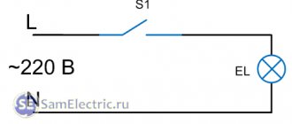
Automatic switches for lighting systems
Despite the fact that installing an automatic switch to power light points is practically not used, such a connection is acceptable to save equipment. In this case, a separate group of “automata” is allocated on the power panel, to which the lighting network is directly connected. The connection is made according to the standard scheme: the contacts open the phase.
It is not recommended to install automatic switches for lighting next to other “automatic machines”.
Otherwise, when you turn off the light, you can mistakenly turn off power to an important node. If possible, such switches are placed in a separate panel.
The advantage of this method: the machines are designed for higher loads and immediately include protection functions. The reliability of such devices is higher in comparison with household switches. The disadvantage is that when used in a residential area, such a switch does not look aesthetically pleasing.
Checking and programming the receiver to the transmitter
Such kits are usually sold already synchronized, but you should check this first. For testing, you will need a cord with a plug and a socket with a short wire attached.
Having stripped the ends of the phase and neutral wires, you need to connect them to the receiver from the side of the two-pin terminal block. On the reverse side, a socket with a lamp is attached to the outer contacts. The plug is plugged into the network, after which you need to try pressing the switch key. If the lamp lights up, then everything is in order. If nothing happens, you need to briefly press the receiver button - the power should go on and the emitter should light up. In this case, you will have to program the receiver.
An example of connecting a lighting device to a receiver
The equipment operates in normal mode, the LED lights up when the lamp is on
Transmitter programming, equipment synchronization
Everything here is extremely simple. Power must be supplied during synchronization. You must press the receiver's command button and hold it until the LED starts flashing. Next, you need to release the button. Now all that remains is to press the switch button, after which the lamp will light up, which will mean successful synchronization of the equipment.
A blinking LED indicates readiness for synchronization
Watch this video on YouTube
Wiring: open or hidden option
Despite the fact that installing a switch may seem like a very simple matter, there are a large number of nuances that a novice electrician must know.
First you need to decide on the type of wiring.
Open wiring is still used in everyday life. It is especially loved by designers who create interiors in retro or loft style.
Electrical wiring is an essential element present in every home.
There are two types of it:
- Open. The wires are laid on top of the wall. They can be secured with decorative rollers or covered with plastic cable ducts.
- Hidden. The wire is laid inside the wall. To do this, channels are cut into its surface into which the cable is laid. After installation, the grooves are sealed with mortar.
Each type of wiring uses a different type of switch. For an open system, choose overhead models that are placed directly on the wall. They are easily recognizable because they are very visible on the surface.
This type of switch was the first to appear and has changed little over the past decades. For closed wiring, internal or built-in models are used.
They are installed in a recess that is previously prepared in the wall. The dimensions of the hole are selected depending on the dimensions of the switch. It is attached inside the recess using special spacer legs.
There is another type of built-in devices - with mounting plates. This option is more convenient to install. After installation, the internal switches practically do not protrude above the wall plane.
Types and classes of contactors
Contactors are designed for remote or automatic switching of power lines for high-power electrical appliances. These electrical products include panel-mounted devices, the power of which is practically unlimited, as well as modular devices for installation on a DIN rail. In the latter case, the permissible current, as a rule, is no more than 63 amperes. Small-sized (non-modular) DIN rail-mount contactors are rated for currents up to 100 A and are actually panel-mount products for a fairly simple reason: their dimensions do not allow the panel faceplate to be correctly installed in place.
Left: 63A DIN rail modular contactor. Right: Panel mount contactor.
The generally accepted classification of magnetic contactors implies their division into values corresponding to the standard size and permissible current load. Thus, modular devices are limited to the 4th value, but there are 7 values in total; with maximum dimensions, the contact group is designed for a current of up to 250 A. Outside the general classification are contactors capable of switching circuits with a current of 1000 A and above, but such devices have a narrow industry application and we will not consider them.
Individual contactor models may have differences in electrical insulation class and permissible switching voltage. There is also a difference in the operating voltage for which the retractor electromagnet coil is designed. Additional differences include:
- number of switched poles of the power contact group (from 1 to 4);
- response time (from 0.01 to 1 s);
- type and efficiency of arc extinguishing devices for different degrees of load inductance;
- permissible number of switching cycles per hour;
- noise and vibration levels;
- the presence and number of additional low-current contacts.
The device of a three-pole contactor with normally open contacts: 1 - coil; 2 - fixed magnetic circuit (core); 3 - movable core; 4 - fixed contacts; 5 — dielectric holder of movable contacts; 6 - moving contacts
The concepts of contactor and starter reflect different essences. Thus, the name contactor implies a monoblock device with only the set of functions provided for by the design. A starter is a set of devices combined within one control assembly. It may include several contactors, as well as additional attachments, protective devices, controls and a housing with a certain degree of dust and moisture protection. Starters, as a rule, are designed to control the operation of asynchronous electric motors.
Combination motor starter
Contactless module selection options
Control can be done using a remote control, which for convenience is made in the form of a key fob.
Before purchasing a contactless limit switch, you must pay attention to the following characteristics:
- block type - the external one can be installed in place of the standard device, the internal one is mounted after removing the chandelier;
- layout - the kit includes a remote control, charging, and rarely a battery and holder;
- features of lighting lamps - the devices are compatible with LEDs, halogens and incandescent bulbs;
- operating frequency – ranges from 2.2 to 5 GHz, which determines the quality of signal reception and transmission;
- range of action – budget models operate at a distance of 10 m, luxury models – at a distance from 100 to 350 m;
- power – contactless equipment has a maximum load limit of 1000 W, but you need to select a power unit with a power 20% more than declared;
- number of clicks – the battery runs out after 10-20 touches, the sensor is designed for the number of touches up to 100 thousand;
- current rating – from 6 to 16 A;
- number of channels - modern devices receive signals from 1-8 sources.
Connection diagram of the limit switch to the starter
Limit switches are mainly used in industrial and household automation, as well as in electrical products. In terms of their functions, the devices are similar to a conventional switch; the only differences are in design. All types of such sensors act on the motor of any drive, as well as the starter and lighting circuits.
A limit switch is a limit switch, which is installed in the control system for generating a signal that gives permission for further operation of the circuit. It usually has several pairs of contacts (open and closed). But there are also contactless limit switches, which consist of an infrared LED and a photocell located opposite each other.