Manufacturers
The most famous models presented on the Russian market are “Ecosvet” and “Claps”. Let's look at their main characteristics.
Switch "Сlaps"
One of the newest developments is the “Claps” cotton switch model. In this device, the sound is processed using a microprocessor; it does not react to any extraneous noise, but is tuned to several claps in a row (this is the most important operating condition).
It is permissible to install several such switches in one room, each of them will react to a certain number of claps, and accordingly turn on the light, humidifier, fan, TV or stereo system. This switch model is suitable for any household appliances that have an electrical cord.
Perhaps to some, the clap switch may seem like a toy or a completely unnecessary device. Others, on the contrary, are passionate about the idea of creating their own “smart home” so that lights and electrical appliances turn on and start working on command or clap. Arrange your life the way you want, but at the same time make it as comfortable as possible.
Ecolight switch
The Ecosvet device is designed to work with 220 Volt light bulbs.
Main parameters of the device:
- load - 300 Watt;
- sound signal spread - from 30 to 150 decibels;
- housing protection level - IP30;
- permissible temperature range - from 20 degrees below zero to 40 degrees above zero;
- cost - from 350 rubles.
“Ekosvet” is fixed with self-tapping screws using the mounting legs. It is not recommended to install the device in noisy rooms. Despite the fact that “Ekosvet” is configured to clap, false alarms are possible.
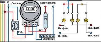
The figure above shows the device connection diagram. "Ecolight" is connected to a conventional switch to provide the ability to de-energize the circuit and stop its operation.
Types of sound switches
Acoustic switches can respond to voice commands and claps
The following types of acoustic switches exist:
- Devices that react to cotton. It is programmed in advance at what number of claps a particular command will be executed.
- Devices that respond to voice or a preset command.
- Combined devices (for example, light-acoustic switch). They can be equipped with sound, light or motion sensors. These are the most technologically advanced devices in which the risk of false alarms is minimized.
- Devices for low-current systems. Used to connect a video camera or transmit a command to security.
Acoustic switches have become popular due to their ease of use. They are useful for the elderly, bedridden patients and young children. Devices of this class are already actively used in the Smart Home system.
Clap switch with microcontroller
A microcontroller is a small piece of silicon covered in plastic and has metal terminals that does not perform any functions without software. Its use in any appliance makes it smart and involves use in the Smart Home system.
Difference from standard sound switch:
- reduced response time to 100 microseconds;
- possibility of reprogramming, setting individual parameters;
- increased range;
- the ability to change the signal threshold value (to eliminate interference and avoid responding to false commands);
- smooth change in lighting brightness;
- fewer components;
- short circuit protection.
Dimmer acoustic switch
Optical-acoustic switch for hidden wiring
Dimming is the regulation of the load that the device consumes. Using dimmers, you can smoothly turn on the light, adjust the brightness of an LED lamp or incandescent light bulb. Not suitable for fluorescent lamps. Dimmer devices can also be used to regulate the temperature in irons, soldering irons, kettles and other household appliances.
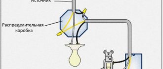
An optical-acoustic switch is needed for dimmer switching on electricity. The operating principle of the microcircuit is as follows:
- the signal in the form of sound reaches the microphone;
- sound is converted into impulse;
- the pulse is sent to the microcontroller and passes through the amplifier, charging the capacitor;
- a large charge is achieved, after which the comparator switches;
- the zero at the output changes to a pulse;
- the transit generator is activated, which sends impulses;
- the triac opens, through which power passes to the lamp;
- the capacitor loses voltage level;
- a signal with increasing phase retardation is supplied to the triac;
- The light turns on smoothly.
If you select all component values correctly, the lamp turns off with a pause of up to 3 minutes. To operate the dimmer, you need a lamp with a power of at least 40 W. The voltage on the optical-acoustic switch varies smoothly in the range from 0 to 220 V.
Advantages:
- Thanks to smooth switching on, the lamp service life increases;
- the ability to create lighting of the required brightness in a certain place;
- the ability to control light using intelligent systems.
Disadvantages include the inability to open the network in the event of a short circuit and the lack of a protective function against overloads.
Dimmers are not recommended for radios, televisions and products with switching power supply, as they cause interference.
Types of switches for home (domestic use)
The various types of switches used in everyday life must be convenient, safe, and have an attractive design. They differ from each other in types and types. Depending on the installation method, the switch can be built-in or installed externally. Nowadays, a rotary key is most often used as controls; such switches are common in Europe.
Types of switches for the home
In the USA they prefer to use lever-type switches (toggle switches), apparently not wanting to break away from tradition. But this is now, but in the old days, when Thomas Edison just made his invention, rotary switches were used. They were known throughout the world in the first half of the 20th century and switched up to several circuits in 3–4 positions (batch switch). Package switches are still used in many old utility panels.
To turn on the lamp, use a single-key switch; for chandeliers, use a two-key or even three-key switch. For rooms such as the toilet and bathroom, use a double light switch. Let us add that in our age of advanced technology, many switches with additional functions have appeared. These are the functions:
- Illuminated switch for night time
- switch with shutdown timer.
- Switches with brightness control.
If everything is clear with the first type of function, then the second is used to save light in small rooms (closets, bathrooms) where people enter for a short time and forget to turn off the lights. And the third can be used together with those lamps that support the dimmer function (dimmer). Sometimes they are included in the kit, since this type of device has not yet been standardized.
Unusual types of switches
A light switch with a motion sensor is another way to save electricity and is very convenient. The light turns on if the infrared sensor detects human movement within the sensor's field of view. Repeated motion may turn off the lights, or a timer may do so after motion has been detected. A switch with a motion sensor does not require any action from a person; his presence is sufficient.
There is one so-called smart switch, this is a clap switch. The way it reacts to noise, it can turn on involuntarily. Inside it there is a microphone, which is also an amplifier and a microprocessor device in order to recognize the nature of the sound. It may not work the first time, as it stores the sound from the user in memory for later comparison.
And there are such things
The floor switch is made in the form of a button with a locking mechanism. It can be turned on by pressing your foot with little force, and is designed in such a way that the weight of your foot will not damage it.
The ceiling switch is also a button with a lock, to which the force is transmitted from a lever with a cord attached to it. The mechanics are hidden behind a decorative cover. To turn it on or off, you need to lightly pull the cord.
Principle of operation
The device operates using a microcontroller installed in it. The controller authorizes turning the light on and off by clapping. If desired, this device can be used to control other electrical household devices (air conditioners, fans, etc.).
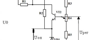
A typical audible light switch contains an electronic microphone with a preamplifier. This component amplifies the sound entering the device, which allows you to record even the quietest pops. The operation of the amplifier is controlled using transistors VT1 and VT2. The circuit is controlled by a pair of resistors R2, and diodes VD1 and VD2 are used to equalize the signal.
The sound from the clap passes through the microphone, where the electrical impulse is amplified and transformed. Next, the sound is equalized due to the work of rectifying diodes. The sound is controlled by a resistor (if the sound volume level is below the specified level, the resistor will prevent the device from operating). When the signal on the capacitor is leveled, the voltage increases and the transistor switch VT3 opens.
The light turns off and on after sequential charging and discharging of the capacitors. At the end of a full cycle of activity (one more bang), the resistor and capacitor C10 are discharged in four seconds. This causes the device to turn off.
Add a link to a discussion of the article on the forum
RadioKot >Schemes >Analog circuits >Household appliances >
| Article tags: | Acoustic switchAdd tag |
The best acoustic switch.
Author: Vladislav Myasin Published 08/20/2010
2010
Many of you have had to fumble for a long time in the dark for the switch of a table lamp, bumping into various objects. This process is usually accompanied by noise and obscene language. But now this has come to an end! The proposed acoustic switch compares favorably with all similar ones: it does not require an external power source, is assembled from common parts (in particular, it does not have a relay), has good sensitivity and protection from network interference, and most importantly, simplicity of design and configuration. Clap your hands and the device will turn on the light, another clap will turn it off. The time spent in each state is unlimited.
Operating principle
The sound signal from the electret microphone is fed to a double amplifier stage using transistors VT1 and VT2. The use of transistors of different conductivities made it possible to avoid parasitic connections. Capacitor C3 protects the circuit from network interference. Resistor R5 bypasses pin 11 of the microcircuit and at the same time acts as a load for transistor VT2. The signal at the output of the amplifier has a sinusoidal shape, but to control the trigger, the signal must be pulsed. Signal conversion is carried out by a single-vibrator made on the DD1.1 block of the K561TM2 microcircuit. The pulse duration at the indicated R6 C4 ratings is 0.5 s.
The heart of the device is a trigger made on the DD1.2 element of the same microcircuit. A trigger is a device that has two stable states and switches from one equilibrium state to another whenever an external control signal is applied. When there is a low voltage level at the output of the trigger (pin 1 of the microcircuit), transistor VT3 is closed and the load is de-energized. At a high logic level at the DD1 output, the transistor VT3 and the thyristor (respectively) are in the open state and the load (EL1) is supplied with supply voltage. The device can only be used with an incandescent lamp, because The load is supplied with a voltage rectified by four diodes connected in a bridge circuit. The power supply is made according to a transformerless circuit. The alternating voltage is rectified by the diode bridge VD2-VD4, passes through the limiting resistor R9 and is filtered by the zener diode VD1 and capacitor C5. If the resistance R9 is too high, the current may not be enough to unlock the thyristor; if it is too low, the zener diode will burn out. The optimal value for R9 is 28 kOhm. The sensitivity of the device to cotton is 4-6 meters. Details
The ELI incandescent lamp is designed for a voltage of 220-235 V and a power of 7-60 W.
Any electret microphone. All fixed resistors are MLT type, the power of resistor R9 is 2W. All capacitors have a voltage of at least 16V. Zener diode VD1 is replaced by KS 175A, D808, D814A or a similar one with a stabilization voltage of 9-12 V. Rectifier diodes VD2-VD4 are replaced by diodes KD226V, KD258B, D112-16 and similar, taking into account that their reverse voltage should not be less than 300 V. Instead of discrete diodes, you can use a ready-made rectifier bridge such as KTs402A, KTs405A, KTs407A. Instead of the VT3 transistor, you can use KT940A-KT940G, KT630A-KT630V and even KT315B. Transistor VT1 of npn structure, VT2 of pnp structure. Thyristor VS1 must have a minimum control electrode current. In addition to what is indicated in the diagram, it can be T112-16-x or another, with worse characteristics, for example, type KU201 K-KU201M, KU202K-KU202N. Installation
The device is assembled on a circuit board and secured in a housing made of dielectric material. Observe the pinout of the microcircuit!
When installing elements, they strive to ensure that their leads have a minimum length (to reduce the influence of interference). The power part is mounted so that the housings of the thyristor and rectifier diodes (in the case of using discrete diodes) do not have contact with other elements (not authorized by the electrical circuit). Do not place resistor R9 near other components to avoid overheating. Do not install the switch on a table, because Shaking during operation may cause false alarms. Establishing
Achtung!
Do not touch the power part of the device connected to the network! Don't forget the fuse! The device does not require any adjustment and, if the components are in working order, starts working immediately after switching on. The sensitivity of the node can be adjusted by changing the noise protection capacitor C3; its capacitance lies in the range of 0.1-1 μF. The higher the capacitance C3, the lower the sensitivity.
Questions, as always, in the Forum.
| What do you think of this article? | Did this device work for you? | |
| 19 | 1 | 1 |
| 0 | 0 |
These articles may also be useful to you:
Simple acoustic switch.(KN)
Voice relay
I offer a simple acoustic machine for switching on various actuators. The essence of the circuit (Fig. 1) is as follows. At a certain level of acoustic noise near the highly sensitive sensor-microphone VM1, the threshold level of which is set by trimming resistor R1, the signal amplified by the operational amplifier DA1 is supplied to the transistor switch VT1-VT2, which supplies power to relay K1. The relay with its contacts (they are not shown in the diagram) closes the load power supply circuit. After the noise stops, the load is turned off.
Fig.1. Schematic diagram of an acoustic machine
This method is used in microdictaphones, which automatically switch to recording mode when there is a sound signal. I use this circuit to automatically turn on the ultrasonic intercom.
This circuit will serve well in a lighting machine. Then it should be supplemented with a final stage with a turn-off delay of 3...4 minutes. If you install such a machine, for example, in the hallway, the light will light up automatically when there is the slightest noise (a door opening or a voice) and go out after a few minutes in complete silence.
In the initial state, both inputs of the DA1 microcircuit are in a state of equilibrium, and a very weak signal, on the order of several millivolts, is received at the base of the transistor VT1, which is insufficient to open the transistor. When sound is applied to the microphone, alternating voltage is supplied to input 2 of the op-amp. The multiply amplified signal from pin 6 of the op-amp, further amplified by transistor VT1, goes to the electronic switch on transistor VT2, which, in turn, switches the actuator - relay K1.
The relay switch-off delay when the sound influence on the microphone disappears depends on the values of C5 and R2. If the delay is not needed, these elements are excluded from the circuit. When a longer turn-off delay is needed, the C5 rating should be increased. With the ratings indicated in the diagram, the turn-off delay when powering the circuit at 12 V will be 1 min ±10%. If the capacitance of capacitor C5 is increased to 2000 μF, the turn-off delay at the same supply voltage will increase to 10 minutes. However, in the latter case, the accuracy of the exposure time is lost and the dependence on the duration of the initial impact of sound vibrations on the microphone increases.
Diode VD1 is used to eliminate bounce of relay K1 contacts. K1 is a low-power relay of type RES10, RES15 for an operating voltage of 9...11 V. To switch powerful load circuits with a high supply voltage, it is necessary to observe safety measures and use a relay with the appropriate permissible current through the contacts. The VM1 microphone is a DEMSh capsule or similar with a winding resistance of 200...250 Ohms and higher. Good results are obtained when using an FEM electret capsule of various modifications as a microphone (previously used as a built-in microphone in cassette tape recorders).
To eliminate interference and other interference, the microphone must be connected to the device with a short shielded cable no more than 20 cm long. When rigidly attaching the device body to other structures (for example, to a vertical wall), you should wrap the microphone capsule with foam rubber and not screw it to the device body, so that interference when various shocks (for example, the slamming of a neighboring door) did not affect the microphone.
As VT2, you can use medium-power silicon transistors KT603, KT630 or their analogues with any letter indices. KT361 with any letter index is suitable as VT1.
A device that is correctly assembled from serviceable parts requires virtually no setup. You only need to use trimming resistor R1 to select the operating threshold of the device.
Required parts for assembly
To assemble an acoustic switch with your own hands, you need to take the following parts:
- Resistors (R1-10k, R2-1M, R3-22k, R4-270k, R5-2k, R6-1.8k, R7-330 Ohm, R8-1.5k)
- Transistors (VT1-KT315, VT2-KT315, VT3-3107)
- Capacitors (S1-3200pf, S2-1uF×10v)
- Diodes VD1
- Miscellaneous: M1 - electret microphone, HL1 - LED or relay, contact block.
Connection rules and specifics
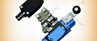
Although limit switches themselves are designed quite simply, they are used in equipment with complex electrical circuits. Consequently, their connection must be carried out by specialists and strictly according to the schematic diagrams, based on the technical features.
Let's look at an example of connecting a simple mechanical switch in a 3D printer. This is necessary in order to set the extreme coordinates for its carriage. The plug-in limit switch has 3 contacts - COM, NO, NC. When the sensor is open, the first and last contacts are at +5V. The second contact (NO) is grounded.
In the diagram, contacts COM (1) and NO (2) are in a closed state, and COM and NC (3) are open. When the printer carriage reaches its extreme position, the COM and NC contacts are connected and it rebounds by 2 mm
The sensor is connected using two wires - red and black. When the device fires, you should hear a typical click. The indicator switch is connected in the same way, but it also has a third wire - green.
Its activation is indicated by a lit LED and a click. Its connectors on the board have designations: for the red wire V (+5 V), for black - G (ground), for green - S (signal).
The same letters indicate the connectors on the optical switch. It will more accurately control the operation of the carriage, but may malfunction in dusty conditions and sunlight. The activation of the optical pair is accompanied by the inclusion of a light-emitting diode and occurs completely silently.
Limit switches are widely used by furniture makers, installing them in wardrobes. Connection is carried out according to the instructions included with each model. The diagram shows the location of the fastening of the plastic structure with the key. For the middle door, it must be installed so that it does not interfere with the correct movement of the other section door along the guides.
The diagrams show the procedure for connecting limit switches for sliding doors in sliding wardrobes (option b) and for swing doors (option a)
If a limit switch is installed for a swing door, it is fixed using self-tapping screws inside the cabinet. When the door is closed, the button presses, opens the circuit and the lighting does not work. When open, the door releases the button and the lighting turns on.
The simplest circuit of an acoustic switch
The simplest effective acoustic switch circuit can be assembled by anyone with the desire and time. Such a switch can be used for various purposes, for example, to turn on and off the lighting in a room using a clap; the same principle of operation and control of any equipment. In general, this acoustic switch is a very useful thing in home use.
This sensor makes it possible to turn on and off power circuits using a clap. Such a device can be used to turn on the light.
It is quite sensitive due to the presence of a double amplifier using low power transistors. It responds well to clap from a distance of five meters from the microphone.
Hidden and outdoor installation methods
The very first thing you have to decide is what type of switch is needed, which can be indoor or outdoor.
In the first case, installation is carried out inside the wall, for which holes of the appropriate size are cut in it. This type of device is used most often, since the wiring is mainly laid in a hidden way.
External switches are used either in wooden houses, in which the wiring is most often done in an open type, or when lighting devices are laid according to a temporary scheme - in this case, in order not to cut the walls, the wires are laid on their surface.
Where is the three switch system used?
Switch equipment with control from three different points ensures practicality. There is no need to walk across the entire room or long corridor to turn on or off the light.
An example of the location of pass-through switches in the bedroom
It is rational to use such a wiring system for a yard or personal plot. We left the house and turned on the light, approached the building and turned it off. We went out, turned it on again, and went to another object.
For example, a room has several beds. The first device will be at the door, the second near one side, the third near the second side of the bed. That is, there is no need to get up and turn off the lights.
Or illumination of the staircase opening, so as not to go up or down in the dark. One switch is installed first at the bottom, the next in the middle, and the third at the end, at the top of the stairs.
It is convenient to use the connection from 3 places in the entrances. On the first floor they turned on the lamp, on the second or third they turned it off. This significantly saves energy.
It is important to install three-point switches in oblong corridors and openings, with several entrances to different rooms. At the beginning of the corridor they turned it on in the middle or at the end they turned it off.
The lamp control circuit is used both in one room and for a large space.
You can use such a lighting system even in walk-through rooms. They turned it on in one room, walked through the room, and turned it off in another room. Convenient and economical.
Connection errors
The main problem during installation is always not taking into account the power of consumers. For most touch-sensitive light switches, the maximum throughput load is limited to 1 kW. In no case should it be exceeded. Most devices of this type do not contain safety elements that block excessive load. Hence their relative fire hazard when the maximum is exceeded.
Another relatively common mistake when installing 220V touch-sensitive light or energy switches is the incorrect connection of the contact groups. For example, it has been noticed more than once that they try to separate the zero of the power supply network with a control device, instead of a phase. Of course, this creates significant problems in its functioning; it becomes simply impossible.
The practical connection of a phase and a COM port for end devices does not make much sense. However, its purpose is different - to communicate with other switches or pass-through switches.
How to connect?
The cotton switch “Ekosvet-X-300-L” in question consists of a block in which the entire circuit is mounted, and two pairs of wires - white and black. The white ones need to be connected to a 220 V electrical network, the black wires are connected to the lighting load.
The lamp receives zero (directly) and phase (through an ordinary household switch) from the distribution box. These two wires are connected to the white wires. You can do this using the old-fashioned twisting method, but it is better to use special self-clamping terminals.
The black wires are connected to the lamp socket itself. That is, with the usual circuit, phase and zero from the supply network would go directly to the lamp socket, and so you also additionally inserted a cotton (or acoustic) light switch into this circuit.
The block itself must be secured to the body of the lighting fixture. The unit has a sensitivity regulator, with which you can set the desired level of cotton. It is most advisable to set the so-called medium level, so that it is not too light, otherwise the switch will start to operate at the slightest tap, and not too strong, so as not to knock off your palms.
The clapper switch is powered through a regular keypad mounted on the wall. If you need to remove a fancy sound device from the circuit, it will be enough to turn off the key switch.
All that remains is to experimentally test the results of your work. When operating correctly, Ecosvet-X-300-L will only respond to clapping of palms. Tap with a hammer, bring a running vacuum cleaner close to the lamp, beat it in a mug with a spoon, turn on a hammer drill, tease with a mobile phone signal. We don’t know what your experiments will show, but there have been cases when cotton switches were triggered by the sound of a working hammer drill or the ringing sound of a metal spoon hitting a mug. This is further confirmation that there are few ideal things in the world; any device, especially in electrical engineering, has, along with advantages, a number of disadvantages (even if completely insignificant).
Payment:
- Mains voltage - 220 V (±10%), 50 Hz;
- Power of connected lamps - up to 1200 W;
- Optical activation threshold ~ 12±5 Lux;
- Acoustic switching threshold - 60±5 dB;
- On time - 50±10 seconds;
- Microphone range: ≤ 5 m;
- Own consumption from the network - ≤ 0.2 W/h;
Useful tips Connection diagrams Principles of operation of devices Main concepts Meters from Energomer Precautions Incandescent lamps Video instructions for the master Testing with a multimeter
Connection and installation
The device is mounted on a one-key or two-key switch so that it receives power from a 220-volt network. This can be done as follows:
Acoustic switch connection diagram
- A typical light bulb connection diagram looks like this: power to the switch is supplied from the panel through the distribution box. The neutral wire is fed to the light source and connected in parallel to the switch;
- It is necessary to break the power circuit to the key switch and install an acoustic device into the gap. The controller is installed in the lamp body;
- Most often, the switch is equipped with two pairs of wires, white and black. Power is supplied in white, loads are connected in black. It is better to make the connection using terminals or simply a winding. Soldering is not used in such circuits.
Advantages and disadvantages
The most important advantage of a sound switch over classic ones is its simplicity and ease of use. The user does not need to think about where to install the switch.
Main advantages:
- work with any electrical appliances or light sources;
- the ability to turn on and off a household appliance or light from anywhere in the room;
- no extra wires;
- reliability and long service life;
- noiselessness;
- safety.
Flaws:
- Modern sensors can recognize the sound that is needed to turn it on and off. The user needs to know exactly what signal the sensor will respond to.
- The sensitivity area is limited. In a large room you will have to clap loudly or move closer to the sensor. If you increase the sensitivity, the sensor may falsely respond to similar sounds.
For radio amateurs who want to make a clap switch with their own hands, the disadvantage is the complexity of the electronic circuit.
Advantages compared to classic ones
The main advantage is the absence of moving elements of a mechanical system driven by human power. As a bonus, the operating principle is based on relays or electronic keys, which gives greater reliability and durability compared to classic options.
The remaining advantages follow from the previous fact. For example, you can make the switch completely sealed, completely removing the impact of the environment on its functionality. It’s not for nothing that all manual control systems with a high IP protection index are built on the basis of touch operating principles. The ease of use is also worthy of mention. To switch the state, just touch, or simply raise your hand to the device.
Principle of operation
Attention The clapper switch is necessary for remote control of electrical appliances and lighting sources. The first clap turns the light on, and the second turns it off
A sensitive microphone picks up the sound wave and transmits the impulse to a power amplifier. Then the signal is sent to the base of the switch to connect the transistor to operation, and the PN junction opens. Current begins to flow into the electrical circuit
The first clap turns the light on, and the second turns it off. A sensitive microphone picks up the sound wave and transmits the impulse to a power amplifier. Then the signal is sent to the base of the switch to connect the transistor to operation, and the PN junction opens. Current begins to flow into the electrical circuit.
To put it simply, the supply and interruption of energy occurs due to the reception of sound signals by a microphone. Used in rooms with minimal noise levels.
Options and features
- Standard product. It is connected to a simple electrical circuit in parallel with the light switch of the device and is adjusted to the desired audio range.
- Combination with timer. Electricity is supplied to the circuit for a certain period of time after receiving the command.
- With an intellectual component. A product of complex design is capable of distinguishing incoming signals and activating a specific device.
- For low current systems. It is used in alarms, to activate cameras, microphones, and provide information to security panels.
Important
It is necessary to think about the installation location in advance. When using a mechanical switch, our homemade switch does not participate in the operation.
Another electrical diagram
There are many options on the Internet of varying complexity depending on the configuration, but not all of them are functional. Defects appear during manufacturing. The presented electrical circuit has been tested in practice.
Here VD1 is intended to protect transistor VT3. To use a relay, a diode must be installed . If you decide to install a light load, we recommend replacing the diode with a jumper.
Simple acoustic switch
The circuit diagram for this acoustic switch was found on one of the bourgeois sites. After checking, it became clear that the circuit was not working, after some experiments and alteration of the circuit - lo and behold! she earned it! Almost all the values of the components used were changed to make the circuit more accessible to beginner radio amateurs, and this is the end result.
Perhaps this is the simplest circuit that can exist; it uses a minimum number of components that are available to everyone. As a result of the alteration, domestic parts were used, which greatly facilitates the selection. The microphone was taken from a Chinese tape recorder; you can also use domestic ones, such as pine.
The microphone amplifier is assembled on two KT315 transistors, but to increase the sensitivity of the microphone it is advisable to use transistors like KT368 or its imported analogues; in general, transistors are not critical.
The power part of the circuit is a powerful bipolar transistor that controls the load, and in order to control large loads a relay was used (12-24 or 220 volts).
The signal from the microphone is amplified and sent to the base of a powerful key, the transition opens and it is at this moment that the relay is triggered, the microphone reacts to loud sounds (for example, clap), the sensitivity of such a circuit is 4-5 meters. At the second clap, the circuit is automatically switched off, therefore, the supply of current to the load is stopped.
The capacitors are electrolytic, the voltage is not so important, you can use the appropriate capacitors with a voltage of 10, 16, 25, 50 volts. The range of supply voltages is also quite wide - from 3.5 to 14 - 16 volts, current consumption in idle mode (when the circuit is turned off) is almost zero
The circuit can be assembled either on a breadboard or mounted mounted, the part values are not critical and can deviate in one direction or another by 20%, but try not to replace the capacitances of the capacitors used, since the best parameters are obtained with the capacitors indicated on the diagram
The range of supply voltages is also quite wide - from 3.5 to 14 - 16 volts, the current consumption in idle mode (when the circuit is turned off) is practically zero. The circuit can be assembled either on a breadboard or by surface mounting; the values of the parts are not critical and may deviate in one direction or another by 20%, but try not to replace the capacitances of the capacitors used, since the best parameters are obtained with the capacitors indicated on the diagram.
List of radioelements
| Designation | Type | Denomination | Quantity | Note | Shop | My notepad |
| Bipolar transistor | KT315A | 2 | Search in the Otron store | To notepad | ||
| Bipolar transistor | KT818A | 1 | Search in the Otron store | To notepad | ||
| Rectifier diode | 1N4007 | 1 | Search in the Otron store | To notepad | ||
| Electrolytic capacitor | 1 µF | 2 | 10-50V | Search in the Otron store | To notepad | |
| Resistor | 10 kOhm | 2 | Search in the Otron store | To notepad | ||
| Resistor | 3 MOhm | 1 | Search in the Otron store | To notepad | ||
| Resistor | 48 kOhm | 1 | Search in the Otron store | To notepad | ||
| Resistor | 1.8 kOhm | 1 | Search in the Otron store | To notepad | ||
| Resistor | 330 Ohm | 1 | Search in the Otron store | To notepad | ||
| Microphone | Pine | 1 | Search in the Otron store | To notepad | ||
| Rel1 | Relay | 1 | Depends on load | Search in the Otron store | To notepad | |
| Add all |
SIMPLE ACOUSTIC RELAY
| radioskot.ru An acoustic switch is a very useful and necessary thing in the household, especially if you want to automate some devices or lighting in your home and add creativity to your home! Using an acoustic switch, you can turn the lighting off and on or use it for other devices, such as an electric kettle or fan. This scheme is fully operational, streamlined and stable. There are many diagrams of similar devices on the Internet, but when assembling them, a lot of performance problems arise and some of them lead to long discussions at the end of which, the problem is often not solved. Below is the diagram itself. The circuit is powered by a voltage of 5 to 9 volts, so choosing a power source will not be difficult. You can use, for example, a crown or other batteries and accumulators. If you need stationary power, then there are many power supply circuits online, even a transformerless one will do. The printed circuit board is made for DIP components, but despite this, it has quite compact dimensions and choosing a housing for it will not be difficult. You can download the printed circuit board from the link: akusticheskiy_vyklyuchatel.zip (downloads: 463) List of parts for assemblyPCB manufacturingI will not explain in detail how to make a printed circuit board, as it will take a lot of time. The PCB file is opened using the sprint-layout 6.0 program: sprint-layout-6.zip (downloads: 394) The circuit uses diode VD1; it is needed to protect transistor VT3 from the EMF of the relay coil. If you connect a relay as a load, then you need to install a diode; if you use a light load, then you can install a jumper instead. After making the board, to avoid oxidation, tin the thresholds with tin. Open the sprint-layout 6.0 program and solder all the parts on it according to the location. If everything is done correctly, the parts and values are not mixed up, then the device should work immediately without any problems. This is what the assembled acoustic switch looks like. And one more photo with a connected battery and an LED on the load. I would like to tell you about one problem that may arise. The circuit contains a 1.5 kOhm resistor R8, if you use an LED as a load, you can leave it, if you plan to install a relay, then replace the resistor with a 2 Ohm. There shouldn't be any more problems)) The result was an inexpensive but very effective and useful device that will definitely find its use in the household!)) Source usamodelkina.ru |