Description of rectifiers
Three-phase bridge rectifier
The main difference between the devices and their single-phase analogues is as follows:
- the first ones are installed in 220 Volt lines and are used to obtain direct currents of insignificant magnitude (up to 50 Amperes);
- three-phase rectifiers are used in circuits where operating (rectified) currents significantly exceed this figure and reach several hundred Amperes.
- Compared to single-phase samples, these devices have a more complex design.
There are known three-phase voltage rectification schemes that make it possible to obtain a minimum level of ripple at the output.
In electrical engineering, they are called “three-phase bridge rectifiers” because the way they open diodes, controlled by voltage polarity, they resemble a one-way bridge across a river. Only the direction of the flow of electrons in them alternates with a frequency of 50 Hz, which is inaccessible for cars to pass alternately in each direction.
Three-phase rectifier circuit with zero terminal
Its timing diagrams are shown in Fig. 2.76.
The ripple factor of the rectified voltage is 0.25, while for a full-wave single-phase rectifier the ripple factor is 0.67. The ripple frequency in a three-phase rectifier is three times higher than the frequency of the supply network.
Operating principle
The operating principle of a three-phase rectifier
The operating principle of any sinusoidal voltage converter is based on the rectifying properties of a special semiconductor element - a germanium or silicon diode. When alternating current flows through it, the positive half-wave freely “passes” through the working electronic junction, biased in the forward direction. When exposed to a negative half-wave, the electrons encounter an obstacle in the form of a potential barrier, so that current cannot flow through the junction.
In the simplest switching circuits, an incomplete cycle of processing variable levels is used, since the second half-wave is irretrievably lost. This significantly reduces the converted power. To preserve the useful component, 2-half-wave rectification circuits were developed, in which the number of diodes was increased to two.
A “full cycle circuit” may contain 4 rectifier elements, but such a circuit belongs to the bridge category.
Half Wave Polyphase Rectifier
First, it is more convenient to consider three-phase half-wave rectifiers, which are easy to manufacture and are used in simple and inexpensive converter circuits. When constructing them, one powerful diode is installed in each phase, serving only this branch.
A total of three semiconductor diodes with loads connected to them are used in a half-wave rectifier device. After studying the diagrams of voltages and currents obtained at the output of the electrical circuit, the following conclusions can be drawn:
- the efficiency (efficiency) of such a device is very low;
- useful power is lost when processing negative half-waves of all three phases;
- When using such devices, it is very difficult to obtain the required load characteristics.
All these disadvantages of half-wave circuits forced developers to complicate them by applying the principle of double parallel conversion.
Full wave rectifier
Some types of power equipment operate only with a large amount of rectified current flowing in the load. Half-wave rectifiers are unable to provide it, which is explained by significant losses in them. To increase the load capacity in three-phase current circuits, full-wave rectifier devices containing two diodes for each phase are increasingly being used.
The classic connection in this case is made according to Larionov’s circuit, after whom the rectifier device itself is named.
An analysis of the operating diagrams of such a rectifier clearly demonstrates its undeniable advantages. When operating these circuits, both positive and negative half-waves are used, which increases the efficiency of the entire converter. This is explained by the fact that the three-phase structure of the circuit, together with full-wave rectification, provides a sixfold increase in the ripple frequency. Due to this, the amplitude of the output signal after smoothing capacitors increases noticeably (compared to a half-wave rectifier), and the power delivered to the load increases.
Regulating characteristics of the rectifier when operating on an active load
The control angle a for each thyristor is counted from the moment the corresponding diode of the uncontrolled rectifier is turned on (in essence, this is true for both the considered single-phase bridge and other controlled rectifiers).
As follows from the last expression, at a = 2l/3 Using the obtained expressions, we will depict the adjustment characteristic graphically (Fig. 4.28, solid line). Operation of the rectifier on an active-inductive load at a control angle i/3 rad (60 el. deg.) (Fig. 4.29). When constructing the timing diagrams, it was assumed that the inductance LH is sufficiently large and the load current is almost constant. Regulating characteristics of the rectifier when operating on an active-inductive load.
The presence of inductance ensures continuous current mode.
It follows that when a = l/2, Ucp = 0. Let us give a graphical representation of the adjustment characteristic (Fig. 4.28, dotted line).
Bridge devices
The “three-phase bridge rectification circuit” allows you to further increase the efficiency of converting AC to DC voltage. It is more convenient to imagine this connection method as a combination of two half-wave circuits with a zero point, in which odd diodes form the cathode group, and even diodes form their anode group. In a three-phase bridge circuit, two branches for processing half-waves of different polarities are actually combined into a single system.
The operating principle of a three-phase bridge rectifier is easiest to imagine as follows:
- when an alternating potential is applied to its input for each half-wave, two of the four diodes turn out to be open, connected as if in a mirror manner;
- in the first case, the positive half-wave of the input voltage is rectified, and in the second, the negative half-wave;
- As a result, at the output of such a cross circuit, there is always a plus at one pole of the bridge, and a minus at the other.
Both in three-phase rectifier bridges and in full-wave circuits, part of the input voltage is lost on diode junctions (no more than 0.6 Volts on each diode).
The total loss per cycle (positive and negative) in a three-phase bridge will thus be 1.2 Volts. Developers of rectifying equipment always take these losses into account and, in order to obtain the required output power, set slightly higher input parameters in advance.
Diagrams or voltage diagrams of bridge circuits are the best confirmation that this method of connecting diodes to the rectifier circuit provides maximum energy transfer. In this case, small voltage losses at the transitions can most often be compensated for due to better filtering in the secondary circuits.
Single-phase rectifiers
The main circuits of single-phase rectifiers are half-wave and full-wave (bridge or midpoint).
The single-phase half-wave circuit is the simplest rectifier circuit.
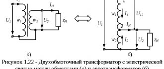
The transformer converts the mains voltage of the primary winding Uc into the voltage of the secondary winding U2 . Since diode D has one-way conductivity, current I2 will flow only with a positive half-wave of the secondary voltage; with a negative half-wave, the diode will be closed. Since the current in the load Rн flows only in one half-cycle, hence the name of the rectifier - half-wave.
The disadvantages of half-wave rectifiers include unipolar current, which, passing through the secondary winding, magnetizes the transformer core, changing its characteristics and reducing efficiency, high ripple levels and high reverse voltage on the diode.
Full-wave rectification circuits are already much more interesting. Of these, the bridge circuit for connecting diodes has gained the most popularity.
The circuit consists of a transformer and four diodes assembled in a bridge. One of the diagonals of the bridge is connected to the terminals of the secondary winding of the transformer, the second diagonal is connected to the load. With a positive potential at point a of the secondary winding of the transformer, the current will flow through the circuit point a of the secondary winding - A - diode D1 - B - load Rн - D - diode D3 . this case, reverse voltage is applied to diodes D2 and D4 When the direction of the E.M.F and the current in the secondary winding changes, a positive potential will appear at point b of the secondary winding of the transformer. The current will flow through the circuit b - C - diode D2 - B - load Rн - D - diode D4 .
Thus, the current in the load does not change its direction. The voltage and current curves on the load repeat (at forward voltage on the diodes U np ≈ 0) in magnitude and shape the rectified half-waves of voltage and current of the secondary winding of the transformer. They pulsate from zero to maximum value.
In addition to the bridge rectification circuit, a bidirectional circuit can be used.
The circuit consists of a transformer with a middle tap on the secondary winding and two diodes. When there is a positive potential at point a , current flows through circuit a - diode D1 - load Rн - tap 0 of the secondary winding. With a positive potential at point b of the secondary winding, current will flow through circuit b - diode D2 - c - load Rн - tap 0 of the secondary winding.
The left figure shows the dependence of the voltage of the secondary winding of the transformer on time, the right shows the change in load current. As follows from the operation of the rectifier, the direction of the current in the load is unchanged. The secondary winding of the transformer is two-phase and each phase operates for half a period. The voltage across the load at any moment is equal to the instantaneous value of the EMF of the phase operating at the moment.
The main disadvantages of this circuit include the need to tap off the secondary winding of the transformer and the high reverse voltage of the diode Urev = 2U2m = 3.14U0, so it is not as widespread as a bridge circuit.
Features of a three-phase bridge and options for its construction
Bridge circuits of three-phase rectifiers have design options that make it possible to improve the parameters of the device. They can be improved by introducing additional valve elements. They are equipped with 6, 9 or even 12 rectifier diodes connected in a star or delta circuit.
The more phases (or pairs of diodes) are used in the rectifier circuit, the lower the level of output voltage ripple.
As an example, consider a device with 12 rectifier diodes. One of the groups of 6 pieces is included in this case according to the “star” circuit with a common zero point, and the second - in a triangle (without ground). Taking into account the fact that the rectifiers are connected in series, the potentials at the system output are summed up, and the ripple frequency in the load turns out to be 12 times greater than the network value (50 Hertz). After filtering, the voltage supplied to the consumer is of higher quality.
Comparison of single-phase and three-phase devices
When comparing three-phase rectification circuits with single-phase analogues, it is important to note the following points:
- the first are used only in 380 Volt power networks, and the second type can be installed in both single-phase and three-phase circuits (one for each phase);
- 380 Volt rectifiers allow you to convert high power and develop significant currents in the load;
- on the other hand, making a three-phase rectifier yourself is somewhat more difficult, since it consists of a larger number of components.
The calculation of a three-phase rectifier will also be more difficult, since in this case the vector components of the effective currents and voltages are taken into account. This is explained by the fact that in 380 Volt circuits the phase parameters are shifted relative to each other by 120 degrees.
It is not difficult to understand the essence of the operation of a three-phase rectifier. To do this, you will need to familiarize yourself with the basics of operation of valve devices and analyze the electrical circuit of their connection. Knowledge of the operating principle of rectifier devices will help the user to use it more effectively in everyday work.
Properties of three-phase voltage
A curve acting only on a resistive load, uncontrolled rectification (with diodes), does not return to zero, unlike a monofrequency device (Graetz bridge). Thus, the ripple is much lower and the dimensions of the inductor and/or smoothing capacitor are less restrictive than for a Heitz bridge.
At least two phases are required to obtain a non-zero output U. Minimum, maximum and average voltage value. Numerically, for a 230 V / 400 V network, the rectified voltage fluctuates between a minimum voltage: 1.5 V min = 1.5 x (1.414×230) = 488 V, and a maximum: 1.732 Vmax = 1.732 x (1.414×230) = 563 IN.
Average value of three-phase rectified voltage: avg = 1.654Vmax = 1.654 x (1.414×230) = 538 V.
Output voltage of three-phase output rectifier (zoom). 3-phase full wave rectifier MDS 130A 400V. 5 terminals: 3 phases, + and -. This rectifier contains 6 diodes.
Thus, the following points can be summarized:
- 6 diodes, 2 diodes per phase - weak ripple compared to a single-wave rectifier (Heetz bridge);
- average value of rectified voltage: 538 V for a network of 230 V / 400 V;
- the neutral is not used by the three-phase rectifier.