It is believed that about half of the failures of electronic boards are associated with a malfunction of the capacitor, without replacing which the further functioning of the circuit is impossible.
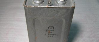
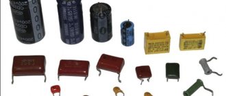
These parts themselves may vary both in characteristics and dimensions; however, they all have one thing in common - the presence of the main controlled parameter (capacity).
In order to check the capacitor installed in the circuit (including the so-called “electrolytes”), it is necessary to measure its capacitance. The faulty part will have to be removed from the circuit and then soldered on with a new one. Some types of capacitors do not need to be soldered, since they are attached by welding or clamps.
Capacity check
There are several ways to check electrolytic capacitors (as well as non-electrolytic ones) to ensure they maintain their nominal capacity (capacity).
But first you need to familiarize yourself with measuring instruments that allow you to correctly estimate the capacitance value of a particular element before soldering anything.
To measure capacitors with nominal capacities up to 20 microfarads, a conventional multimeter with the appropriate function may be sufficient. An inexpensive device like DT9802A can be used as such a meter.
To assess the condition of elements with high ratings, you will need a special device such as an “RLC meter”. Using such a device, you can test not only capacitors, but also such common elements as a resistor and inductor.
Checking the capacitor with a digital multimeter:
Often a faulty capacitor swells and is noticeable without the use of any instruments.
A simple, but not very effective method of identifying a malfunction is checking with a conventional ohmmeter, the reading of which can be used to judge the integrity of the dielectric gasket.
This method is usually used when the device does not have a capacitance measurement function. For these purposes, a simple pointer device can be used, switched to resistance measurement mode.
When the ends of the probe touch the legs of a working element, the arrow should deviate slightly and then return to a similar state.
If the readings on the device have changed, and the needle, after the deviation, has stopped at some final resistance value, this means that the capacitor is broken and must be replaced.
Replacing a capacitor without desoldering it from the board
Repair conditions vary, and changing a capacitor on a multilayer (PC motherboard, for example) printed circuit board is not the same as changing a capacitor in a power supply (single-layer, single-sided printed circuit board). You must be extremely careful and careful. Unfortunately, not everyone was born with a soldering iron in their hands, and repairing (or trying to repair) something is very necessary.
As I already wrote in the first half of the article, most often the cause of breakdowns is capacitors. Therefore, replacing capacitors is the most common type of repair, at least in my case. Specialized workshops have special equipment for these purposes. If you don’t have it, you have to use conventional equipment (flux, solder and soldering iron). In this case, experience helps a lot.
And if there is no experience, then an attempt at repair may well end in failure. Just for such cases, I hasten to share a method for replacing capacitors without desoldering them from the printed circuit board. The method is outwardly rather inaccurate and to some extent more dangerous than the previous one, but for personal use it will do.
The main advantage of this method is that the contact pads of the board will have to be subjected to much less heat. At least twice. Printing on cheap motherboards quite often peels off due to heat. The tracks come off, and fixing this later is quite problematic.
The disadvantage of this method is that you still have to put pressure on the board, which can also lead to negative consequences. Although from my personal experience I have never had to press hard. In this case, there is every chance of soldering to the legs remaining after mechanical removal of the capacitor.
So, replacing a capacitor begins with removing the damaged part from the motherboard.
You need to place your finger on the capacitor and, with light pressure, try to swing it up and down and left and right. If the capacitor swings left and right, then the legs are located along the vertical axis (as in the photo), otherwise along the horizontal axis. You can also determine the position of the legs by the negative marker (a strip on the capacitor body indicating the negative contact).
Next, you should press the capacitor along the axis of its legs, but not sharply, but smoothly, slowly increasing the load. As a result, the leg is separated from the body, then we repeat the procedure for the second leg (press from the opposite side).
Sometimes the leg is pulled out along with the capacitor due to bad solder. In this case, you can slightly widen the resulting hole (I do this with a piece of guitar string) and insert a piece of copper wire there, preferably the same thickness as the leg.
Half the job is done, now we move directly to replacing the capacitor. It is worth noting that the solder does not stick well to the part of the leg that was inside the capacitor body and it is better to bite it off with wire cutters, leaving a small part. Then the legs of the capacitor prepared for replacement and the legs of the old capacitor are treated with solder and soldered. It is most convenient to solder the capacitor by placing it on the board at an angle of 45 degrees. Then you can easily stand him at attention.
The resulting appearance is, of course, unaesthetic, but it works and this method is much simpler and safer than the previous one in terms of heating the board with a soldering iron. Happy renovation!
It is believed that about half of the failures of electronic boards are associated with a malfunction of the capacitor, without replacing which the further functioning of the circuit is impossible.
These parts themselves may vary both in characteristics and dimensions; however, they all have one thing in common - the presence of the main controlled parameter (capacity).
In order to check the capacitor installed in the circuit (including the so-called “electrolytes”), it is necessary to measure its capacitance. The faulty part will have to be removed from the circuit and then soldered on with a new one. Some types of capacitors do not need to be soldered, since they are attached by welding or clamps.
Check in board
One of the most common ways to check a capacitor without removing it from the circuit is to connect in parallel another, previously working capacitor with a known rating.
This method allows you to judge the serviceability of the element by the device indicator, which shows the total capacity of two parallel-connected “condensers”. When capacitors are connected in parallel, their capacitances add up.
With this approach, it is possible to do without soldering the capacitor in order to remove it from the circuit in which it is shunted by elements (resistors) connected in parallel.
However, the possibilities of using this method are limited by the permissible voltages operating in a given electronic circuit and on the board of the device under test.
The method is effective only at small potentials comparable to the maximum voltage values for which the electrolytic capacitor is designed.
Measurement Precautions
For those who decide to independently check the serviceability of the capacitors built into the circuit and then solder them, we recommend adhering to the following rules.
- Be sure to ensure that the circuit is completely de-energized. To do this, use the same multimeter turned on in voltage measurement mode to check that it is absent at all control points on the board.
- When measuring “suspicious” capacitors built into a circuit, you should be careful not to accidentally damage the elements connected in parallel to it.
- And finally, additionally mounted elements in the circuit must be soldered with extreme caution so as not to damage the rest of the circuit.
Only if all these conditions are met is it possible to keep the controlled device in working condition.
How to resolder a capacitor on the motherboard
Before soldering a new capacitor, you need to unsolder the old one.
You should unsolder a damaged or faulty element from the motherboard as quickly as possible, so as not to overheat the contact pads, which otherwise may simply fall off. To free the legs of the soldered element from solder, you should warm up the seat well. Only if it is sufficiently warmed up when soldering the capacitor is it possible to avoid damaging the board tracks.
When holding a small capacitor on one side, you need to try not to get burned, since its contact becomes hot when heated by a soldering iron.
In addition, you need to be as careful as possible and not use too much force, as the soldering iron tip can break off and damage adjacent parts.
The sequence of actions is as follows:
- First, turn off the power to the computer, disconnect not only the network cable, but also other power wires.
- Remove the cover and unscrew the motherboard.
- They inspect the board and find a damaged element, study its parameters (on the markings), and buy a replacement.
- Note what polarity the capacitor was connected to (you can take a photo).
- Using a soldering station or a soldering iron, the damaged capacitor is soldered out.
- Install and solder a new one.
After removing the capacitor, there remains a free space, which should first be carefully cleaned of solder residues using a suction.
Some radio amateurs use a sharpened match (toothpick) for this purpose, through which the mounting hole is pierced while simultaneously heating with the tip of the soldering iron tip.
Another way to free holes from solder residue involves drilling it out with a drill of a suitable size.
Upon completion of the preparation of the site for the new element, its legs should first be molded accordingly so that they easily fit into the mounting sockets. All that remains to be done after this is to solder it in place of the burnt one.
Replacing a capacitor without desoldering it from the board
Repair conditions vary, and changing a capacitor on a multilayer (PC motherboard, for example) printed circuit board is not the same as changing a capacitor in a power supply (single-layer, single-sided printed circuit board). You must be extremely careful and careful. Unfortunately, not everyone was born with a soldering iron in their hands, and repairing (or trying to repair) something is very necessary.
As I already wrote in the first half of the article, most often the cause of breakdowns is capacitors. Therefore, replacing capacitors is the most common type of repair, at least in my case. Specialized workshops have special equipment for these purposes. If you don’t have it, you have to use conventional equipment (flux, solder and soldering iron). In this case, experience helps a lot.
And if there is no experience, then an attempt at repair may well end in failure. Just for such cases, I hasten to share a method for replacing capacitors without desoldering them from the printed circuit board. The method is outwardly rather inaccurate and to some extent more dangerous than the previous one, but for personal use it will do.
The main advantage of this method is that the contact pads of the board will have to be subjected to much less heat. At least twice. Printing on cheap motherboards quite often peels off due to heat. The tracks come off, and fixing this later is quite problematic.
The disadvantage of this method is that you still have to put pressure on the board, which can also lead to negative consequences. Although from my personal experience I have never had to press hard. In this case, there is every chance of soldering to the legs remaining after mechanical removal of the capacitor.
So, replacing a capacitor begins with removing the damaged part from the motherboard.
You need to place your finger on the capacitor and, with light pressure, try to swing it up and down and left and right. If the capacitor swings left and right, then the legs are located along the vertical axis (as in the photo), otherwise along the horizontal axis. You can also determine the position of the legs by the negative marker (a strip on the capacitor body indicating the negative contact).
Next, you should press the capacitor along the axis of its legs, but not sharply, but smoothly, slowly increasing the load. As a result, the leg is separated from the body, then we repeat the procedure for the second leg (press from the opposite side).
Sometimes the leg is pulled out along with the capacitor due to bad solder. In this case, you can slightly widen the resulting hole (I do this with a piece of guitar string) and insert a piece of copper wire there, preferably the same thickness as the leg.
Half the job is done, now we move directly to replacing the capacitor. It is worth noting that the solder does not stick well to the part of the leg that was inside the capacitor body and it is better to bite it off with wire cutters, leaving a small part. Then the legs of the capacitor prepared for replacement and the legs of the old capacitor are treated with solder and soldered. It is most convenient to solder the capacitor by placing it on the board at an angle of 45 degrees. Then you can easily stand him at attention.
The resulting appearance is, of course, unaesthetic, but it works and this method is much simpler and safer than the previous one in terms of heating the board with a soldering iron. Happy renovation!
In the element base of a computer (and not only) there is one bottleneck - electrolytic capacitors. They contain an electrolyte; the electrolyte is a liquid. Therefore, heating such a capacitor leads to its failure, as the electrolyte evaporates. And heating in the system unit is a regular occurrence.
Therefore, replacing capacitors is a matter of time. More than half of the failures of motherboards in the middle and lower price categories are due to dry or swollen capacitors. Even more often, computer power supplies break down for this reason.
Since the printing on modern boards is very dense, replacing capacitors must be done very carefully. You can damage and not notice a small unframed element or break (short) tracks, the thickness and distance between which is slightly greater than the thickness of a human hair. It’s quite difficult to fix something like this later. So be careful.
So, to replace capacitors you will need a soldering iron with a thin tip with a power of 25-30 W, a piece of thick guitar string or a thick needle, soldering flux or rosin.
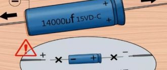
If you reverse the polarity when replacing an electrolytic capacitor or install a capacitor with a low voltage rating, it may well explode. And here's what it looks like:
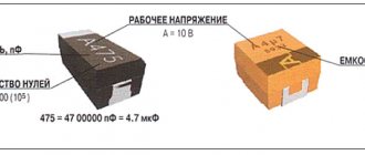
So, carefully select the replacement part and install it correctly. Electrolytic capacitors are always marked with a negative terminal (usually a vertical stripe of a different color from the body color). On the printed circuit board, the hole for the negative contact is also marked (usually with black shading or solid white). The ratings are written on the capacitor body. There are several of them: voltage, capacity, tolerances and temperature.
The first two are always present, the others may be absent. Voltage: 16V (16 volts). Capacitance: 220µF (220 microfarads). These values are very important when replacing. The voltage can be chosen equal or with a higher nominal value. But the capacitance affects the charging/discharging time of the capacitor and in some cases can be important for a section of the circuit.
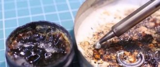
Therefore, the capacity should be selected equal to that indicated on the case. On the left in the photo below is a green swollen (or leaking) capacitor. In general, there are constant problems with these green capacitors. The most common candidates for replacement. On the right is a working capacitor, which we will solder.
The capacitor is soldered as follows: first find the legs of the capacitor on the back side of the board (for me this is the most difficult moment). Then heat one of the legs and lightly press the capacitor body from the side of the heated leg. When the solder melts, the capacitor tilts. Carry out a similar procedure with the second leg. Usually the capacitor is removed in two steps.
There is no need to rush, and there is no need to press too hard. The motherboard is not a double-sided PCB, but a multilayer one (imagine a wafer). Overdoing it can damage the contacts on the inner layers of the printed circuit board. So no fanaticism. By the way, long-term heating can also damage the board, for example, lead to peeling or tearing of the contact pad. Therefore, there is no need to press hard with a soldering iron either. We lean the soldering iron and press lightly on the capacitor.
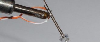
After removing the damaged capacitor, it is necessary to make holes so that the new capacitor can be inserted freely or with little effort. For these purposes, I use a guitar string of the same thickness as the legs of the part being soldered. A sewing needle is also suitable for these purposes, but needles are now made of ordinary iron, and strings are made of steel. There is a chance that the needle will get caught in the solder and break when you try to pull it out. And the string is quite flexible and steel and solder adhere much worse than iron.
When removing capacitors, solder most often clogs the holes in the board. If you try to solder the capacitor in the same way that I advised you to solder it, you can damage the contact pad and the track leading to it. Not the end of the world, but a very undesirable occurrence. Therefore, if the holes are not clogged with solder, they simply need to be expanded. And if you do, then you need to press the end of the string or needle tightly to the hole, and on the other side of the board, lean the soldering iron against this hole. If this option is inconvenient, then the soldering iron tip should be leaned against the string almost at the base. When the solder melts, the string will fit into the hole. At this moment you need to rotate it so that it does not grab the solder.
After obtaining and expanding the hole, it is necessary to remove excess solder from its edges, if any, otherwise, during soldering of the capacitor, a tin cap may form, which can solder adjacent tracks in those places where the seal is dense. Pay attention to the photo below - how close the tracks are to the holes. Soldering this is very easy, but difficult to notice, since the installed capacitor interferes with the view. Therefore, it is very advisable to remove excess solder.
If you don’t have a radio market nearby, then most likely you can only find a used capacitor for replacement. Before installation, its legs should be treated, if necessary. It is advisable to remove all solder from the legs. I usually coat the legs with flux and tin them with a clean soldering iron tip, the solder collects on the soldering iron tip. Then I scrape the legs of the capacitor with a utility knife (just in case).
That's all, actually. We insert the capacitor, lubricate the legs with flux and solder. By the way, if you use pine rosin, it is better to crush it into powder and apply it to the installation site than to dip a soldering iron in a piece of rosin. Then it will work out neatly.
Soldering process
Before soldering, you need to insert the legs into the socket, observing the polarity.
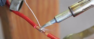
The negative leg of the part is usually shorter than the positive leg; it is installed on the “minus” pad (usually painted white). Soldering must be done from the reverse side; to do this, the board is turned over and the legs are bent. Soldering the capacitor will be much easier if you first moisten the contact “spots” with a drop of flux.
The soldering iron is heated, brought to the contact pad, and the solder wire is brought to it. Use a sting to touch the solder so that a droplet slides onto the soldering site. So you need to solder all the contacts sequentially, and then bite off the extra protruding legs with pliers.
You may not be able to solder beautifully the first time, and you will need to practice. It is better to learn soldering methods in advance on unnecessary parts. After replacing the faulty element, you should try to turn on the motherboard and check its functionality.
How to solder an electrolytic capacitor with your own hands?
Of all the discrete electronic components, electrolytic capacitors can be some of the most difficult to use. Here are some tips for wiring and soldering these capacitors by hand. Definition of Electrolytic Capacitors Electrolytic capacitors, like other components, come in two basic formats. Through-hole capacitors have long leads designed to fit through holes in a circuit, while surface mount devices (SMDs) include flat contacts that sit at the edge of the board. Many top-notch circuit manufacturers perform repair work, and while many capacitors are susceptible to burnout when circuits fail, they are difficult to identify due to differences in manufacturing style and markings. Through-hole electrolytic capacitors are usually cylindrical or can be shaped. Exceptions to this rule occur with power film capacitors and some high voltage ceramic caps. Electrolytic devices are also known to have both terminals on the bottom of the capacitor instead of opposite circular faces, but some are double terminals. SMD electrolytic capacitors retain the basic profile, but their markings are on the top of the capacitor and their bases include a rectangular block. Unlike most capacitors, electrolytic caps are polarized devices. Their negative terminals are often identified by a colorless long stripe that may or may not include "-" signs, and their ratings are usually given in volts (V) and picofarads or microfarads (pF, μF, uF). SMDs, on the other hand, are usually identified by a stripe of color on half of the top surface of the device next to the markings. Circuit building tools
Proper soldering equipment is very simple. The following table describes the various tools needed to build a diagram. Table
| Soldering tools | Soldering with temperature controls and a secure mounting rack are essential for any maintenance or circuit assembly task. Be sure that the tin is not a plumber's type device, as these tools are not suitable for fine detail work. |
| Solder Remover | Use a product that makes it easier to remove solder from a circuit component during replacement or after too much solder has been improperly placed on a new component. |
| Magnifier | Although most through-hole electrolytic capacitors are large enough to see standard terminals from just 0.1 inches away, you need to use a magnifying glass because this is impossible to see with the naked eye. Installed magnifying glasses serve to reduce eye strain and simplify work. These can be combined using hand-held devices that include plier clamps or mounting brackets to hold tiny components and circuit boards in a stable position while the user works. |
Removing a Capacitor Removing Through-Through Capacitors
Electrolytic capacitors are actually a little easier to remove than other components due to their larger size. Start by heating the solder joint by flowing solder onto one of the wires. This may require additional molten solder or temperature adjustments. Once the solder is wet, use braid or wick to remove it, then rock the device back and forth. Repeat this process on both ends until the device is released. Once the faulty capacitor is identified, it must be removed to make room for replacement. Removing SMD Capacitors Remove the SMD capacitors by applying solder or solder paste to the pins, gently pushing the device to release it. If you use a gun to overheat, be careful not to remove other components nearby. Steps to install a new capacitor: Through-hole capacitors
Insert the wires through the holes, being sure to line up the negative side of the device with the correctly marked hole on the circuit board. Push the capacitor down until it is as close to the board as possible. Then bend the leads to hold it in place. Apply flux, then bend the solder around the pads and press until the device is properly secured. SMD capacitors
Tin the leads with a small amount of solder. Place the capacitor down using SMD tweezers or similar and heat the solder pads until the capacitor is securely seated. It is important not to heat the device body. Summary
Electrolytic capacitors are ubiquitous components in analog and digital circuits. Although these devices can be difficult to work with, following a structured soldering procedure will make your job easier.