Formula
The capacitor charge current is found using the formula presented below. It is measured in farads, which is equal to a coulomb or volt.
Formula for finding the charge of a capacitor
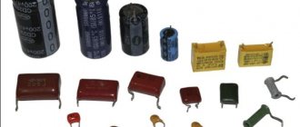
In general, this is an element of the electrical network that accumulates and stores voltage in it. It comes in different types and sizes, for example, electrolytic, ceramic and tantalum. It consists mainly of several conductive plates with a dielectric. Its capacity depends on the size of the dielectric and the filler between the plates. Charges using electricity. The capacitor charge current can be determined using measuring instruments and a formula.
Divisions of capacitors with the possibility of changing the capacitance
According to this parameter, parts in this category are divided into:
- permanent;
- variables;
- tuning.
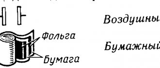
Specific names determine the main design features and intended purpose. A typical permanent capacitor is created from conductive plates, rolled into a roll to reduce size. A dielectric is installed between them. The assembly is placed in a metal case or filled with polymer to provide the necessary security parameters.
Radial capacitor with electrolytic filler
In variable and tuning models, sets of mechanically driven plates are used. By changing the position of the working elements, the required capacity value is established. Each product is designed for a specific range of operating parameters. Such capacitors are used to fine-tune the oscillatory circuit. They are installed in radio-electronic units to regulate individual operating parameters during operation.
formulas for capacitors
One of the important elements of the electrical circuit is a capacitor, the formulas for which allow you to calculate and select the most suitable option. The main function of this device is to accumulate a certain amount of electricity. The simplest system includes two electrodes or plates separated by a dielectric.
- What is the capacitance of a capacitor measured in?
- Capacitor Energy Formula
- Capacitor charge formula
- Capacitor Leakage Current Formula
Capacitance
Concept of capacity
When studying the processes occurring in circuits with a capacitor connected to them, it was discovered that the charge and discharge times for different samples of this element differ significantly from one another. Based on this fact, the concept of capacitance was introduced, defined as the ability of a capacitor to accumulate charge under the influence of a given voltage:
After this, the change in charge on its plates over time can be represented as:
But since Q = CU , then through simple calculations we get:
that is, the current flows through the capacitor in such a way that it begins to lead the voltage by 90 degrees in phase. The same result is obtained when using other mathematical approaches to this electrical process.
Vector representation
For greater clarity, electrical engineering uses a vector representation of the processes considered, and to quantify the slowdown of the reaction, the concept of capacitance is introduced (see photo below).
The vector diagram also shows that the current in the capacitor circuit is 90 degrees ahead of the voltage in phase.
Additional Information. When studying the “behavior” of a coil in a sinusoidal current circuit, it was discovered that in it, on the contrary, it lags in phase with the voltage.
In both cases, there is a difference in the phase characteristics of the processes, indicating the reactive nature of the load in the alternating EMF circuit.
Ignoring differential calculations that are difficult to describe, to represent the resistance of a capacitive load we obtain:
It follows from it that the resistance created by the capacitor is inversely proportional to the frequency of the alternating signal and the capacitance of the element installed in the circuit. This dependence allows you to build on the basis of a capacitor such frequency-dependent circuits as:
- Integrating and differentiating chains (together with a passive resistor);
- LF and HF filter elements;
- Reactive circuits used to improve the load characteristics of power equipment;
- Resonant circuits of series and parallel type.
In the first case, using a capacitance, it is possible to arbitrarily change the shape of rectangular pulses, increasing their duration (integration) or shortening it (differentiation).
Filter chains and resonant circuits are widely used in linear circuits of various classes (amplifiers, converters, generators and similar devices).
Capacitance graph
It has been proven that current flows through a capacitor only under the influence of a harmonically varying voltage. In this case, the current strength in the circuit is determined by the capacitance of a given element, so the greater the capacitance of the capacitor, the greater its value.
Expert opinion
It-Technology, Electrical power and electronics specialist
Ask questions to the “Specialist for modernization of energy generation systems”
Equivalent series resistance of a capacitor. Taking into account that the current fluctuations coincide at the active resistance, are ahead of the voltage fluctuations at the capacitive resistance, and lag behind the voltage fluctuations at the inductive resistance, the last equality can be written as follows. Ask, I'm in touch!
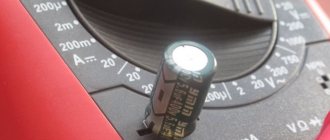
Measuring capacitance of a capacitor with a multimeter and special devices
Some multimeters have a capacitance measurement feature. Take these common models: M890D, AM-1083, DT9205A, UT139C, etc.
There are also digital capacitance meters available, such as the XC6013L or A6013L.
Using any of these devices, you can not only find out the exact capacitance of the capacitor, but also make sure that there is no short circuit between the plates or an internal break in one of the terminals.
Electrical capacity
When connecting devices for charge condensation, as a rule, the technician is interested in the electrical capacitance that will result.
Electrical capacity shows the ability of a two-terminal network to accumulate charge and is measured in farads. It may seem that the higher this value, the better, but in practice it is not possible to create all possible containers in the world, moreover, this is often not necessary, since all devices used every day use standard condensation devices.
You can connect several devices for condensation in a circuit, creating one condensing container, and the value of the characteristic value will depend on the type of connection, and there are long-known formulas for its calculation.
Capacitance of a parallel plate capacitor
The capacitance of a solitary conductor is rarely used in practice. In normal situations, guides are not solitary. A charged conductor interacts with surrounding bodies and induces charges on them, and the potential of the field of these induced charges (according to the principle of superposition!) changes the potential of the conductor itself. In this case, it can no longer be argued that the potential of the conductor will be directly proportional to its charge, and the concept of the capacitance of the conductor itself actually loses its meaning.
It is possible, however, to create a system of charged conductors, which, even if a significant charge accumulates on them, almost does not interact with surrounding bodies. Then we can talk about capacitance again - but this time about the capacitance of this system of conductors.
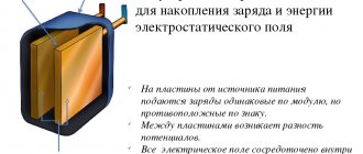
The simplest and most important example of such a system is a parallel-plate capacitor. It consists of two parallel metal plates (called plates) separated by a layer of dielectric. In this case, the distance between the plates is much less than their own dimensions.
First, let's look at an air capacitor with air between the plates.
Let the charges of the plates be equal and . This is exactly what happens in real electrical circuits: the charges of the plates are equal in magnitude and opposite in sign. The quantity - the charge of the positive plate - is called the charge of the capacitor.
Let be the area of each plate. Let's find the field created by the plates in the surrounding space.
Since the dimensions of the plates are large compared to the distance between them, the field of each plate far from its edges can be considered a uniform field of an infinite charged plane:
Capacitor equivalent circuit
Equivalent Circuit: Since the plates in a capacitor have some resistance, and since no dielectric is a perfect insulator, there is no such thing as a "perfect" capacitor. In real life, a capacitor has both series resistance and parallel resistance (leakage resistance), interacting with its purely capacitive characteristics:
Figure 2 – Capacitor equivalent circuit
Fortunately, it is relatively easy to make capacitors with very low series resistance and very high leakage resistance!
Polar and non-polar capacitors
It is very important to separate capacitors into polar and non-polar .
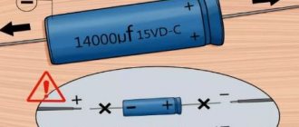
Oxide-based devices: electrolytic aluminum and tantalum are usually polar, which means that if their polarity is reversed, they will fail. Moreover, this failure will be accompanied by violent electrochemical reactions up to the explosion of the capacitor.
Polar capacitors are always marked. As a rule, on electrolytic capacitors, the negative terminal (cathode) is marked with a contrasting stripe on the case; for tantalum capacitors (in yellow rectangular cases), the positive terminal (anode) is marked with a stripe. If you have doubts about the marking, it is better to find the documentation for this capacitor and make sure.
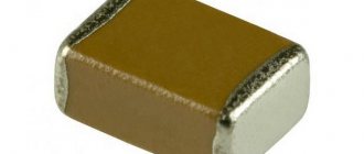
Non-polar capacitors can be connected to the circuit in any direction. For example, multilayer ceramic capacitors are non-polar.
Operating principle and characteristics of capacitors
The capacitor device consists of two metal plates separated by a thin layer of dielectric. The ratio of the size and location of the plates and the characteristics of the dielectric material determine the capacitance indicator.
The design development of any type of capacitor aims to obtain maximum capacity based on minimum dimensions to save space on the device's printed circuit board. One of the most popular forms in appearance is in the form of a barrel, inside of which metal plates are twisted with a dielectric between them. The first capacitor, invented in the city of Leiden (Netherlands) in 1745, was called the “Leyden jar”.
The principle of operation of the component is the ability to charge and discharge. Charging is possible due to the location of the plates at a short distance from each other. Nearby charges, separated by a dielectric, are attracted to each other and retained on the plates, and the capacitor itself thus stores energy. After turning off the power source, the component is ready to release energy into the circuit, discharge.
Parameters and properties that determine performance, quality and durability:
- electrical capacitance;
- specific capacitance;
- permissible deviation;
- electrical strength;
- self-inductance;
- dielectric absorption;
- losses;
- stability;
- reliability.
The ability to accumulate charge determines the electrical capacitance of the capacitor. When calculating capacity you need to know:
- covering area;
- distance between plates;
- dielectric constant of the dielectric material.
To increase the capacitance, you need to increase the area of the plates, reduce the distance between them, and use a dielectric whose material has a high dielectric constant.
To denote capacitance, the Farad (F) is used - a unit of measurement that received its name in honor of the English physicist Michael Faraday. However, 1 Farad is too large. For example, the capacity of our planet is less than 1 Farad. In electronics, smaller values are used: microfarad (μF, millionth of a Farad) and picofarad (pF, millionth of a microfarad).
Watch this video on YouTube
Specific capacitance is calculated from the ratio of capacitance to the mass (volume) of the dielectric. This indicator is influenced by geometric dimensions, and an increase in specific capacitance is achieved by reducing the volume of the dielectric, but this increases the risk of breakdown.
The permissible deviation of the nominal capacity value from the actual value determines the accuracy class. According to GOST, there are 5 accuracy classes that determine future use. High-precision components are used in high-responsibility circuits.
Electrical strength determines the ability to hold a charge and maintain operating properties. The charges stored on the plates tend to each other, affecting the dielectric
Electric strength is an important property of a capacitor that determines the duration of its use. In case of improper operation, dielectric breakdown will occur and the component will fail.
Self-inductance is taken into account in AC circuits with inductors. For DC circuits it is not taken into account.
Dielectric absorption is the appearance of voltage on the plates during rapid discharge. The absorption phenomenon is taken into account for the safe operation of high-voltage electrical devices, because In the event of a short circuit there is a danger to life.
The losses are due to the low current transmission of the dielectric. When operating components of electronic devices in different temperature conditions and different humidity, the loss quality factor has an influence. It is also affected by the operating frequency. At low frequencies, losses in the dielectric affect, at high frequencies - in the metal.
Stability is a capacitor parameter that is also influenced by ambient temperature. Its effects are divided into reversible, characterized by a temperature coefficient, and irreversible, characterized by a temperature instability coefficient.
The reliability of the capacitor primarily depends on the operating conditions. Analysis of breakdowns suggests that in 80% of cases the cause of failure is breakdown.
Depending on the purpose, type and area of application, the sizes of capacitors vary. The smallest and miniature ones, ranging in size from a few millimeters to several centimeters, are used in electronics, and the largest are used in industry.
Capacitor charge formula
To perform charging, the capacitor must be connected to a DC circuit. A generator can be used for this purpose. Every generator has internal resistance. When the circuit is closed, the capacitor is charged. A voltage appears between its plates equal to the electromotive force of the generator: Uc = E.
The plate connected to the positive pole of the generator is charged positively (+q), and the other plate receives an equal charge with a negative value (-q). The amount of charge q is directly proportional to the capacitance of the capacitor C and the voltage on the plates Uc. This dependence is expressed by the formula: q = C x Uc.
During the charging process, one of the capacitor plates gains and the other loses a certain number of electrons. They are transferred through an external circuit under the influence of the electromotive force of the generator. This movement is an electric current, also known as charging capacitive current (Icharge).
The charging current flows in the circuit in almost thousandths of a second, until the moment the capacitor voltage becomes equal to the electromotive force of the generator. The voltage increases smoothly and then gradually slows down. Further, the capacitor voltage value will be constant. During charging, a charging current flows through the circuit. At the very beginning, it reaches its maximum value, since the capacitor voltage has a zero value. According to Ohm's law, Izar = E/Ri, since the entire emf of the generator is applied to the resistance Ri.
Where and how are capacitors used?
Before we start talking about the scope of application of capacitors, let us remember that a capacitor is two plates separated by a dielectric. Therefore, current cannot flow through the capacitor (to a first approximation). However, in a circuit with a capacitor, charge and discharge processes can occur. And during these processes, charge or discharge currents will flow in the circuit.
Thus, if an alternating voltage is applied to a circuit containing a capacitor, an alternating current will flow through it. Therefore, the capacitor can be characterized by such a value as capacitive reactance (denoted in the technical literature as Xc).
Capacitance depends on the capacitance of the capacitor and the frequency of the applied voltage. The higher the capacitance and frequency, the lower the capacitance. The use of capacitors in filtering circuits of power supplies is based on these effects.
In computer power supplies, a full-wave rectification circuit with two diodes and a filter capacitor is used to obtain constant voltages of +3.3, +5, and +12 V. Without a capacitor, the load will have a pulsating voltage of the same polarity.
The DC voltage source can be represented as an equivalent circuit of a generator and two resistances, where R1 is the internal resistance of the rectifier, and R2 is the capacitance of the capacitor.
A generator is the sum of direct and alternating voltages (pulsating voltage contains a direct and alternating component).
Thus, the signal from the generator is fed to a frequency-dependent voltage divider. The output signal is taken from the lower arm (capacitor). For constant voltage, the resistance of the capacitor is very high, much greater than the resistance of the rectifier. Therefore, the DC voltage does not decrease.
For alternating voltage, the resistance of the capacitor is very small, much less than the resistance of the rectifier, so the alternating component is greatly attenuated.
In general, this combination of active resistance and capacitor is called a low-pass filter, which passes the DC component and some range of low frequencies.
The higher the frequency of the input AC voltage, the more it is attenuated.
Since strong suppression of alternating voltage ripple is necessary, high-capacity electrolytic capacitors are used.
The purpose of ceramic SMD capacitors on the motherboard is to suppress high-frequency noise that occurs when switching transistors in microcircuits. Thus, electrolytic capacitors filter relatively low-frequency interference and ripple, while ceramic capacitors filter higher-frequency ones.
Let's give another example of separating a variable and a constant component. In the circuit in the figure, let the signal at point A have a constant component of 5 V and a variable amplitude of 2 V.
After the capacitor, at point B there will be only an alternating component with the same amplitude of 2 V (if the capacitance of the capacitor is small for such a frequency). Interesting, isn't it?
Essentially, this is also a frequency-dependent voltage divider, where the load resistance acts as the lower arm. This combination is called a high-pass filter, which does not transmit DC components and low frequencies, since the capacitance will be large for them.
We advise you to study Thermocouple: what is it?
In conclusion, we note a small detail: since the maximum voltage on the capacitor will be equal to the sum of the constant and variable components, its operating voltage must be no less than this value.
You can buy capacitors
To be continued.
Determining the capacitance of an unknown capacitor
Method: measuring capacitance with special devices
The easiest way is to measure the capacitance using a device that has a capacitance measurement function. This is already clear, and this was already discussed at the beginning of the article and there is nothing more to add.
If you're not very comfortable with instruments, you can try putting together a simple homemade tester. You can find good schemes on the Internet (more complex, simpler, very simple).
Well, or finally fork out for a universal tester that measures capacitance up to 100,000 µF, ESR, resistance, inductance, allows you to check diodes and measure the parameters of transistors. How many times has he helped me out!
Capacitors in AC circuits
If AC power is connected to a resistor, then the current and voltage are proportional. That is, they reach their peak at the same time. If a capacitor is connected to an alternating voltage, the maximum current and voltage are proportional. The current reaches its maximum at the ¼ cycle point of the peak voltage (resulting in 90°).
Current maximums at ¼ voltage cycle, in cases where a capacitor is connected to the alternating voltage
For a circuit with a capacitor, the V/I value is not constant. But Vmax/Imax is useful and is called resistance capacitance. It's still voltage divided by current, and the unit is ohms. The XC value is based on capacitance and frequency:
The capacitor affects the current and, when fully charged, can completely stop it. The AC voltage is constant, so there is an RMS current limited by the capacitor. This is the capacitor's effective resistance to alternating current, so the root mean square (Irms) is given by a version of Ohm's law:
(Vrms – root mean square voltage).
What kind of lighting do you prefer?
Built-in Chandelier
Expert opinion
It-Technology, Electrical power and electronics specialist
Ask questions to the “Specialist for modernization of energy generation systems”
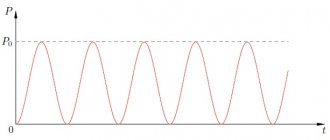
What does capacitor voltage affect? Electrics from A to Z If you plot the power in an AC circuit with a capacitor, you can make sure that the capacitor, like pure inductance, does not consume active power. Ask, I'm in touch!
Relative dielectric constant
An equally significant factor influencing the capacitance of a capacitor is the property of the material between the plates as the relative dielectric constant
.
This is a dimensionless physical quantity that shows how many times the force of interaction between two free charges in a dielectric is less than in vacuum .
Materials with a higher dielectric constant allow for greater capacitance. This is explained by the polarization
– displacement of electrons of dielectric atoms towards the positively charged capacitor plate.
Polarization creates an internal electric field in the dielectric, which weakens the overall potential (voltage) difference of the capacitor. Voltage U prevents the flow of charge Q to the capacitor. Therefore, lowering the voltage helps place more electrical charge on the capacitor.
Below are examples of dielectric constant values for some insulating materials used in capacitors.
Air – 1.0005
Paper – from 2.5 to 3.5
Glass – from 3 to 10
Mica – from 5 to 7
Metal oxide powders – from 6 to 20
What is a capacitor and its main characteristics
A capacitor is a radio component that works as a storage device for electrical energy. To make it clearer how it works, it can be thought of as a kind of small battery. Indicated by two parallel lines.
Designations of various types of capacitors in the diagrams. Most often, electrolytic capacitors fail, so it’s worth remembering their designation
The main characteristic of any type of capacitor is capacity. This is the amount of charge that it is able to accumulate. It is measured in Farads (abbreviated simply as the letter F or Ф), or rather, in smaller units:
- microfarads - µF is 10-6 farads,
- nanofarads - nF is 10-9 farads;
- picofarads - pF is 10-12 farads.
The second important characteristic is the rated voltage. This is the voltage at which long-term trouble-free operation is guaranteed. For example, 4700 uF 35 V, where 35 V is the nominal voltage of 35 volts.
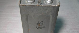
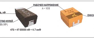
For large capacitors, the capacitance and voltage are indicated on the case
You cannot place a capacitor in a circuit with a higher voltage than that indicated on it. Otherwise, it will quickly fail.
You can use 50 volt capacitors instead of 25 volt capacitors. But this is sometimes impractical, since those that are designed for higher voltage are more expensive, and their dimensions are larger.
Formulas for measuring capacitor voltage
The numerical indicator of voltage is equal to electromotive force. It is also defined as the capacity divided by the amount of charge, based on the formula for determining its value. According to another rule, the voltage is equal to the leakage current divided by the insulation resistance.
You might be interested in How to choose a color temperature
Basic formulas for calculation
In general, a capacitor is a device for accumulating electrical charge, consisting of several plate electrodes that are separated by dielectrics. The device has an electrode measured in farads. One farad is equal to one coulomb. The voltage of the device is affected by the current, the indicators of which can be calculated using the formulas described above.
Conduction triangle for a capacitor
We divide the sides of the current triangles, expressed in units of current, by the voltage U. We obtain a similar conductivity triangle (Fig. 13.16, b), the legs of which are active G = IG/U and capacitive Вс = Iс/U conductivity, and the hypotenuse is the total conductivity of the circuit Y = I/U . From the triangle of conductivities
The relationship between the effective values of voltage and current is expressed by the formulas
I = UY
U = I/Y (13.35)
From the triangles of currents and conductivities, determine the quantities
cosφ = IG/I = G/Y; sinφ = Ic/I = Bc/Y; tanφ = IC/IG = Bc/G. (13.36)
There is no capacitor of the required value: what to do
Very often, novice home craftsmen, having discovered a breakdown of the device, try to independently discover the cause. Having seen a burnt part, they try to find a similar one, and if this fails, they take the device for repair. In fact, it is not necessary that the indicators coincide. You can use smaller capacitors by connecting them in a circuit. The main thing is to do it right. In this case, 3 goals are achieved at once - the breakdown is eliminated, experience is gained, and family budget funds are saved.
Let's try to figure out what connection methods exist and what tasks the series and parallel connection of capacitors are designed for. Often it is impossible to do without connecting capacitors into a battery. The main thing is to do it right
How to properly connect capacitors
To find out how to connect a capacitor correctly, you need to figure out exactly what type it is. There are a huge variety of these electronic devices. All capacitors are divided into two groups:
- polar (electrolytic) - when connecting them, it is necessary to take into account where the part has a positive and negative contact;
- non-polar (all others) - these capacitors are capable of operating on alternating current; they do not have positive and negative terminals.
Then you need to consider the design of the electronic component. From this point of view, capacitors can be:
- Inferential. They are connected to the board using thin copper legs, coated (tinned) with a layer of solder for protection.
- For surface mounting (SMD). Mainly used in compact electronics. Very miniature, often not exceeding 1 mm in diameter.
It is also important to take into account the operating voltage of the capacitor. This is especially important for electrolytic devices of this type, because if their rated voltage is exceeded, they will most likely explode, spraying boiling electrolyte in all directions.
Important! There are two notches on the cover of the electrolytic capacitor. These weak points serve to instantly depressurize the product in the event of excessive internal pressure. When repairing and adjusting equipment, avoid directing the notches onto your face or clothing. In an emergency, hot electrolyte may splash out from them.
The maximum voltage threshold is no less critical for other types of capacitors, especially those with small dimensions and unable to withstand overloads for a long time.
The last but not least important factor to consider when connecting capacitors is their capacitance. It is measured in microfarads (after Michael Faraday). This is their main characteristic, which is why capacitors are often called electrical capacitances. In some electronic devices, this parameter can deviate significantly, both downward and upward. In others, an error of 1% is unacceptable.