- January 22, 2021
- Tools and equipment
- Yulia Tolok
In everyday life, a situation often arises when it is necessary to connect an electric motor, but there is no necessary power source. Then the use of a different type of voltage is required. This usually happens if the engine needs to be connected to third-party equipment (lathe, homemade device). Capacitors are used for this purpose. They come in several types, so you need to have at least a basic understanding of which capacitors to use to start an electric motor in each specific case.
What is a capacitor
A capacitor is a radio element consisting of two plates with a dielectric between them. Its main purpose is to create a buffer between the plates to store charge. There are three types of capacitors:
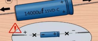
- Polar. Used in DC systems. These are electrolytic capacitors, which, due to their special structure, have polarity. They are not very suitable for connecting to AC sources due to the destruction of the dielectric layer with the release of a large amount of heat, which sometimes even leads to explosions.
- Non-polar. Designed for use in both types of circuits.
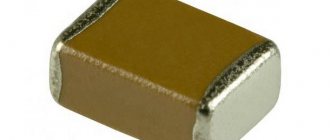
- Electrolytic. This category includes only non-polar capacitors of this type. They have an oxide film as a lining. Optimal option for low-frequency motors due to the high possible capacity.
Each type of engine has its own characteristics for selecting a capacitor. This determines what capacity the capacitor is needed to start the engine, what rated voltage and what type.
Description of DC Capacitor
Electrical circuits are of two types - constant or variable . It all depends on how the electric current flows in them. Devices on these circuits behave differently.
To consider how a capacitor will behave in a DC circuit, you need to:
- Take a DC power supply and determine the voltage value. For example, "12 Volts".
- Install a light bulb rated for the same voltage.
- Install a capacitor in the network.
There will be no effect: the light bulb will not light up, but if you remove the capacitor from the circuit, the light will appear.
If the device is connected to an alternating current network, it simply will not close, and therefore no electric current will be able to pass here. Permanent - not able to pass through the network in which the capacitor is connected. It's all because of the plates of this device, or rather, the dielectric that separates these plates. You can make sure that there is no voltage in the direct current network in other ways. You can connect anything to the network, the main thing is that a source of constant electric current is included in the circuit. The element that will signal the absence of voltage in the network or, conversely, its presence, can also be any electrical appliance. It is best to use a light bulb for these purposes: it will glow if there is electric current, and will not light if there is no voltage in the network.
We can conclude that the capacitor is not capable of conducting direct current through itself, but this conclusion is incorrect. In fact, an electric current appears immediately after applying voltage, but disappears instantly. In this case, it passes within only a few fractions of a second. The exact duration depends on how capacious the device is, but this is usually not taken into account.
Connecting a single-phase motor
To connect an asynchronous motor to a single-phase circuit, a voltage of 220 V is usually used. But to start it, it is necessary to create a rotary displacement torque of the rotor. For this purpose, a starting winding is used, which is additional and functions only when starting. The phase shift is set on it using a capacitor.
The capacity is selected according to the following principle. The total capacitance (operating and starting) per 100 W of power is approximately 1 µF. If you need to select capacitors to start a 1.5 kW electric motor, then it is quite easy to calculate: 1.5 x 1000: 100 x 1 = 15 µF. Thus, to connect a single-phase asynchronous motor with a power of 1.5 kW, it is necessary to use a working and starting capacitor with a total capacity of 15 μF.
Such engines have several operating modes:
- Connected additional winding to the starting capacitor. The capacitance is selected based on 70 microfarads per kilowatt of power.
- An additional winding is used throughout the entire period of operation together with a working capacitor, the capacity is about 30 µF.
- Connecting two types of capacitors at the same time.
Asynchronous or collector: how to distinguish
In general, you can distinguish the type of engine by the plate - the nameplate - on which its data and type are written. But this is only if it has not been repaired. After all, anything can be under the casing. So if you are not sure, it is better to determine the type yourself.
This is what a new single-phase capacitor motor looks like
How do collector motors work?
You can distinguish between asynchronous and commutator motors by their structure. The collectors must have brushes. They are located near the collector. Another mandatory attribute of this type of engine is the presence of a copper drum, divided into sections.
Such motors are produced only as single-phase ones; they are often installed in household appliances, as they allow one to obtain a large number of revolutions at the start and after acceleration. They are also convenient because they easily allow you to change the direction of rotation - you just need to change the polarity. It is also easy to organize a change in the rotation speed by changing the amplitude of the supply voltage or its cutoff angle. That is why such engines are used in most household and construction equipment.
Commutator motor structure
The disadvantages of commutator motors are high operating noise at high speeds. Remember a drill, an angle grinder, a vacuum cleaner, a washing machine, etc. The noise during their operation is decent. At low speeds, commutator motors are not so noisy (washing machine), but not all tools operate in this mode.
The second unpleasant point is that the presence of brushes and constant friction leads to the need for regular maintenance. If the current collector is not cleaned, contamination with graphite (from brushes being worn out) can cause adjacent sections in the drum to become connected and the motor simply stops working.
Asynchronous
An asynchronous motor has a starter and a rotor, and can be single or three phase. In this article we consider connecting single-phase motors, so we will only talk about them.
Asynchronous motors are characterized by a low noise level during operation, therefore they are installed in equipment whose operating noise is critical. These are air conditioners, split systems, refrigerators.
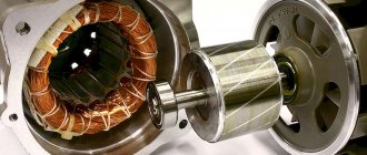
Structure of an asynchronous motor
There are two types of single-phase asynchronous motors - bifilar (with a starting winding) and capacitor. The whole difference is that in bifilar single-phase motors the starting winding works only until the motor accelerates. Afterwards it is turned off by a special device - a centrifugal switch or a start-up relay (in refrigerators). This is necessary, since after overclocking it only reduces efficiency.
In capacitor single-phase motors, the capacitor winding runs all the time. Two windings - main and auxiliary - are shifted relative to each other by 90°. Thanks to this, you can change the direction of rotation. The capacitor on such engines is usually attached to the housing and is easy to identify by this feature.
You can more accurately determine the bifolar or capacitor motor in front of you by measuring the windings. If the resistance of the auxiliary winding is less than half (the difference can be even more significant), most likely this is a bifolar motor and this auxiliary winding is a starting winding, which means that a switch or starting relay must be present in the circuit. In capacitor motors, both windings are constantly in operation and connecting a single-phase motor is possible through a regular button, toggle switch, or automatic machine.
Capacity calculation methods
To calculate which capacitors are best used to start an electric motor, the following formula is used:
- C = k x If: Uc,
Where:
- k is the coefficient, it differs depending on the type of connection, 4800 is a triangle and 2800 is a star;
- If – starter current (indicated on the engine);
- Uc is the network voltage, in this case 220 volts.
The output is a capacitance measured in µF (one millionth of a Farad). It can be calculated in another way, using power as the main parameter.
Every 100 W of motor power corresponds to 7 µF. It should not be forgotten that the starter winding must receive a current no higher than the rated current.
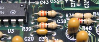
About power decoupling with examples
When I participated in the 7400 competition, I realized that many of the submitted logic circuits lacked the simplest protective elements to operate reliably. One of the most common design flaws was the lack of locking tanks. Later, after reading an article about Murphy's law, I decided to write a little about decoupling and blocking capacitors. As someone who can be called an old-timer in the field of electronics, I became familiar with the problem of lack of decoupling first-hand. I built my first high-speed circuit while an intern at a large electronics manufacturing company. That circuit, a digital frequency counter, was assembled on the logic of the 74Fxx family and operated at a frequency of 11 MHz (at that time this was considered a very high frequency). It was a board measuring 23 × 16 cm (Double Eurocard), containing about 40 microcircuits connected by wire wrap. When the time came to turn it on, I saw that the circuit did not work as it should, but produced complete nonsense. After checking the assembly several times, I told my supervisor about the problem, and he looked at the board and said: “There are not enough bypass capacitors. Put them on power near each microcircuit, then we’ll talk.” Completely confused, I did as I was told, and lo and behold! - everything worked immediately. Why did a seemingly unaffected capacitance make the circuit work? My supervisor told me about switching surges, conductor inductance, and decoupling. I admit it was a few years before I really understood what he was saying back then, but the lesson was learned: always put capacitors to power digital chips.
The terms “blocking capacitor” and “decoupling” are not random words, but have a very specific meaning in this context: decoupling is an action aimed at (partially) separating the power circuits of the microcircuit from the general power source; Bypass capacitor - a capacitor installed in such a way that it bypasses the power supply to the microcircuit and acts as a local power source.
Why is all this so important? Take a look here for example:
Figure 1. No blocking capacitors.
Does this look like a digital signal? This is the kind of nonsense you get without blocking capacitors.
Please note that clock speed is not important
. The problem lies in the rising and falling edges of the signal. Thus, the same considerations apply to systems operating at 1 Hz, 20 kHz, or 50 MHz. The frequencies used in the examples below are chosen so that they can be easily observed on an oscilloscope.
It should be noted that at a high frequency the failure occurs faster than at a low frequency due to the greater number of edges per unit time. However, this does not mean that low-frequency circuits will work reliably. This is far from true; they will fail just as easily, according to Murphy's law. Oh, and by the way, have you thought about your little microcontrollers running at 16 MHz?
To see what is happening, you need to measure the currents flowing through the circuit. Here is a simple experimental setup put together for illustration:
Figure 2. Connecting the inverter.
Figure 3. Measuring circuit.
The pulse generator is connected to a 74HC04 inverter loaded with a capacitance of 10 pF. The inverter output signal, TP1, is shown in the top waveform. The power source is connected to pins 7 and 14 of the microcircuit. A 10 Ohm current measuring resistor is connected to the ground conductor gap.
The voltage at point TP2 is proportional to the current consumed by the microcircuit and is displayed on the lower oscillogram. The blocking capacitor can be connected or disconnected as needed. The oscilloscope probes are equipped with 1:10 dividers, so the vertical scale of the waveform must be multiplied by 10. All unused inputs of the 74HC04 are grounded. The installation looks like this:
Figure 4. Installation assembled on a breadboard.
Figure 5 shows problems occurring at high and low frequencies. The pictures on the left are without a blocking capacitor, on the right are with it.
Figure 5. Output voltage (upper channel) and current consumption (lower channel). At the top is the clock frequency of 330 kHz, at the bottom is 3.3 MHz. On the left - without a blocking capacitor, on the right - with it.
Some observations from Figure 5:
- The measured current is only the current through the GND leg and the bypass capacitor. It does not exactly match the current drawn by the chip. It is difficult to measure the current through the Vcc and GND legs at the same time (limitations imposed by the design of the oscilloscope. -
Translator's note )
. However, measuring current through the GND pin is sufficient for illustrative purposes. - At logical “1”, a high-frequency “ringing” is observed at the output. Its swing is greater than 2 V, and the surges exceed the supply voltage. Adding a bypass capacitor reduces ringing to an almost negligible level. The surge still remains, but fades much faster
- The edges of the signal correspond to surges (“needles”) of the consumed current. Adding a bypass capacitor reduces these overshoots and makes them symmetrical on rising and falling edges. The emission range is from -22 to +45 mA without a blocking capacitor and from -32 to +36 mA with it.
- The symmetrical shape of the current in the presence of a blocking capacitor indicates that energy is stored and extracted back. This is a very important feature.
- Residual RF ringing depends largely on the position of the oscilloscope probe (not shown), which suggests that the circuit contains parasitic LC elements and RF antennas. The location on the board and the relative position of the connecting wires have a significant impact on the amplitude and frequency of vibrations. This interference cannot be completely eliminated, but it can be greatly reduced by properly routing the PCB.
Let's take a closer look at the signal fronts:
Figure 6. Fronts of output voltage (upper channel) and current consumption (lower channel). Above is the trailing (falling) front, below is the leading (rising) front. On the left - without a blocking capacitor, on the right - with it.
The 74HC04 chip is made using CMOS technology. This means that the static current consumption is close to zero. Current is consumed only when switching from “0” to “1” and from “1” to “0”. When switching, all load and parasitic capacitances must be recharged. For the experimental circuit, the load has a capacitance of 10 pF. Here you need to add pin capacitances and parasitic capacitances, which are approximately 5+2 pF. The oscilloscope probe has a capacitance of 10 pF, which also needs to be taken into account. Thus, the total load capacitance at the inverter output is approximately 27 pF.
The output capacitance needs to be charged from 0 to 5 V in approximately 4.3 ns. Assuming for simplicity that the charging current is constant, let’s estimate its value: Q = I t = C U
I
= (5 27 10-12)/(4.3 10-9) = 31.4 mA
This means that at each switching, a huge flow (by CMOS standards) .
)
current.
Where does the energy for this come from? Of course, from the power source. Figure 6 clearly shows that the current does not appear instantly, but increases to a certain level and then drops again. This behavior clearly indicates the presence of inductive elements. This is best seen in Figure 6 on the right, where the current reaches its maximum as the output voltage drops to zero. The current then drops, causing the output voltage to sag. The calculated current matches the measured current quite well, considering that only a rudimentary estimate was made.
Let's take another close look at the bottom half of Figure 6. On the left, the output voltage does not reach 5 V for some time, and on the right, it reaches almost immediately. Without a blocking capacitor, the microcircuit does not have enough supply power to generate a steep edge, and the voltage is stuck at 4 volts. The blocking capacitor provides the required instantaneous power for some time.
The blocking capacitor is approximately 4000 times larger than the load capacitance, which means that the supply voltage drop should be expected to be 4000 times lower than the output voltage swing .
)
- about 1-2 mV.
When switching back, from “1” to “0”, as in Figure 6 above, the blocking capacitor acts as a reservoir to receive the released energy. The load capacitance is discharged and the current must flow to ground. However, the energy cannot be instantly transferred to the power supply, and the bypass capacitor will temporarily store it.
The main power supply cannot provide the chip with sufficient power due to the inductance of the conductors.
Each wire has parasitic inductance that prevents the current from changing. From the definition of inductance: U = L · dI / dt ⇒ dI = U · dt / L
From this equation it can be seen that the change in current is inversely proportional to the inductance. In other words, if the inductance increases, it becomes more difficult to change the current in a given period of time, all other things being equal. In addition, a change in current causes a voltage drop across the inductor. The longer the wire (or trace on the board), the higher the inductance it has, the more it resists rapid changes in current, and the greater the voltage drop will be.
The blocking capacitor is a local energy storage device. It should always be mounted as close as possible to the chip's power pins to minimize the inductance of the leads from the capacitor to the chip. This scheme decouples general and local power circuits.
The chip consists of six inverters, so the circuit can be modified to increase the current consumption:
Figure 7. Experimental setup with additional load.
Figure 8. Output voltage (upper channel) and current consumption (lower channel) for a circuit with an additional load. At the top is the clock frequency of 330 kHz, at the bottom is 3.3 MHz. On the left - without a blocking capacitor, on the right - with it.
Note the different Y-axis scale for the current measurement channel compared to Figures 5 and 6.
The current through the GND pin now spikes around 70 mA in the absence of the bypass capacitor. If the latter is installed, we again observe a symmetrical form of emissions with an amplitude of ±50 mA at rising and falling edges.
Notice that the signal edge, as seen in Figure 8 bottom left, is now much flatter. The microcircuit simply does not have enough energy to switch quickly. Installing a blocking capacitor (Figure 8 on the right) restores the slope of the front to an acceptable level.
Figure 9. Fronts of output voltage (upper channel) and current consumption (lower channel). On the left is the trailing (falling) front, on the right is the leading (rising) front. The blocking capacitor is installed.
A closer look at the signal edges reveals an increased current surge due to greater energy demands. The load on the microcircuit is approximately six times higher than before (the first inverter is loaded on the input capacitances of the remaining inverters, which are 5 times 5 pF).
This was just a simple example - a chip of six inverters. Now extrapolate the above to a complex logic circuit containing many elements and many internal connections. It contains a lot of parasitic capacitances that must be recharged whenever the input signals change. Finally, imagine a microcontroller consisting of many thousands of gates.
The above explanations and illustrations should make it clear that the blocking capacitor is an important element that performs its special function. It stores energy from the power source locally, releases it when needed, and also receives excess energy.
The local energy storage is constantly replenished from the main power supply through the Vcc conductor. At the same time, excess energy must be dumped into the power supply through the GND wire. Dumping energy into the blocking capacitor increases the voltage across it, and, in fact, briefly creates a local area on the circuit with a different potential. Eliminating this imbalance is very important and is done through grounding. (Here, grounding does not mean connection to the mass of our planet, but connection to the common wire of the power source. - Approx. Transl.
)
Printed circuit boards often have separate ground planes, which are very effective at connecting elements to a common power supply conductor. A well-designed ground layout is paramount to discharging excess energy. But be careful, eddy currents can arise in a continuous grounded layer, and numerous connections with a common wire can form the so-called. earth loops.
It's always a good idea to reach out to an experienced developer you know. Most mistakes have already been made by someone before, and there is no need to repeat them ad infinitum.
Connecting two capacitors for a three-phase motor
To start the engine under load, a starting capacitor must be added. It operates in the first few seconds during startup and stops working when the rotor reaches operating mode (speed). To select a capacitor for the engine in this case, you should know that its design voltage exceeds that of the working capacitor by 1.5 times, the capacitance by 2.5-3 times.
More than one capacitor can be connected. If you connect them in parallel, the capacity will increase, which is convenient for calculations.
After turning on the engine the first time, it is necessary to monitor its operation. It shouldn't get too hot. If it is not clear which capacitors to use for the electric motor in this case, then the correct answer is with a lower capacitance. The operating voltage is at least 450 V. In order for the engine to operate efficiently, it is necessary not only to correctly determine all the parameters of the capacitor used, but also to take into account the conditions of its load or operation.
conclusions
1. Indeed, the larger the capacitance and the smaller the dimensions, the worse the linearity. Here is the dependence of distortion on capacitance for capacitors K10-17a, which have housings of almost the same size:
2. Small capacitors (less than 5 nF) have good linearity. Moreover, their distortions (within the limits of my measurement error) do not depend on the capacitance. Probably a different dielectric is used there?
3. Capacitors in larger packages are more linear. Compare 2-3 and 2-5 (they are shown broken down in the photo above). The volume of the case, and most importantly, the volume of the “crystal” is several times larger, and the distortions differ by more than an order of magnitude!
4. Different types of capacitors have different characteristics for the same capacitance. (Well, this is understandable, it’s not clear why they produce so many different ones?!)
5. I wonder what happens in SMD capacitors, which are even smaller in size?
6. The dependence “the better the TKE, the better the linearity” (and this is a widely held opinion) is generally confirmed, but not entirely unambiguously. Somewhere it’s like this, and somewhere it’s the other way around. Apparently, everything depends on the properties of the dielectric, and while TKE is standardized by manufacturers and specifications, linearity is not. But in order to thoroughly understand the issue, you need to conduct many experiments with capacitors of different TKE groups, and this is not yet possible.
7. The sound quality of an amplifier with high-capacity ceramic pass-through capacitors will be spoiled.
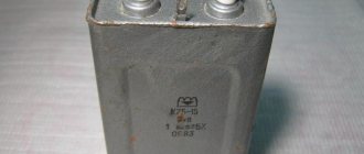
Differences between starting and running capacitors
The starting capacitor is needed to start the motor, so it works for a short time at the beginning, after which it turns off, while the motor continues to work (a phase shift is created in the winding). Consequently, the time when the starting capacitor is activated is about 3 seconds, since over a longer period it can become very hot and lead to a short circuit in the motor circuit, which will certainly be followed by failure of the circuit elements.
This type of capacitor is used on electric motors whose connection diagram provides for this starting mode. For other engines, it can also be used if, at the moment of starting, an increased load is created on the shaft, which does not allow the rotor to rotate freely.
The working capacitor sets the phase shift for constant operation of the engine, therefore it is calculated taking into account longer operation. During a cycle phase change, a voltage appears on the capacitor that exceeds the supply voltage. This occurs due to the fact that, together with the winding, an oscillatory circuit is created. The latter is also important to consider.
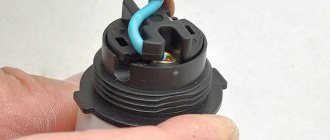
Connection diagram for a 220 Volt commutator motor
Electric drills, rotary hammers, grinders and some models of automatic washing machines use a synchronous commutator motor. It successfully starts and works in single-phase networks without unnecessary starting devices.
In order to connect a commutator electric motor . it is necessary to connect the two ends No. 2 and No. 3 with a jumper, one coming from the armature, and the other from the stator. And connect the remaining 2 ends to a 220 Volt power supply.
Remember that when connecting a commutator electric motor without an electronics unit, it will only operate at maximum speed, and when starting there will be a strong jerk, high starting current, and sparking on the commutator.
It could be a 2 speed motor . then the 3rd end will come out of the stator from half of its winding. When connected to it, the shaft rotation speed will decrease, but this increases the risk of insulation failure when starting the motor.
To change the direction of rotation, it is necessary to swap the ends of the stator or armature connection.
Comparison of both types of capacitors
The working and starting capacitors have the following differences:
- Use in various connection circuits: working and starting.
- The working capacitor generates an electromagnetic field for the main cycle of engine operation; the starting capacitor sets the phase shift between two windings - working and additional - at the beginning of operation.
- The first is connected in series with the auxiliary winding, the second in parallel with the main winding.
- The working capacitor is active all the time while the engine is on, the starting capacitor is only at the start until it reaches constant mode.
- As already noted, the principle of selecting a container is also different. Every 100 W corresponds to 7 µF for the running capacitor and 13-17 µF for the starting capacitor. The coefficient of increase in the maximum permissible voltage is also different compared to the nominal one: for operating voltage - 1.15, starting voltage - 2-2.5.
These rules help to at least roughly understand what kind of capacitor is needed to start an electric motor.
Surge Protectors
Below is an example of a power regulator based on the 78xx family (where xx is the output voltage):
The capacitors shown in the figure are usually ceramic.
For the above capacitors, you should/can additionally supply electrolytic or tantalum capacitors at both the input and output. Their capacity depends on your project, so you will have to select them yourself. Below are some rules for their selection:
- increase the capacitance of the capacitor at the input of the stabilizer when the voltage source
- connected with a long wire is poorly efficient, and your device consumes significant current intermittently
- the device operates at the maximum stabilizer current limit
The capacitance of these capacitors should be approximately in the range from 10 µF to 470 µF. In very special cases when operating at the limit of the stabilizer parameters, use up to 1000 µF.
In this case, it is better to use a capacitor of smaller capacity, but with a low equivalent series resistance (Low ESR).
If you don't have a low ESR capacitor, you can use two regular ones in parallel, which will cause the total ESR of the capacitor to drop.
Connection principles
From a safety point of view, it is recommended to follow these rules:
- Each time after turning off the engine, discharge the capacitor. The charge accumulated by it can lead to failure of the circuit. Some capacitors may have a built-in discharge resistor that is selected to fully discharge within 50 seconds of turning off the power.
- Live parts must be insulated so as not to accidentally touch them.
- The capacitor housing must be securely fastened so that it does not move during operation.
If you have doubts about your ability to select the correct capacitors to start the electric motor and connect the device yourself, it is recommended to seek help from a specialist.
Sometimes the question may arise as to what kind of capacitor is needed for a DC motor. The fact is that such engines do not need capacitive elements in the circuit. But capacitors can also be used there; they are placed on the brush mechanism to eliminate interference. They have a completely different operating principle.
Asynchronous or collector: how to distinguish
In general, you can distinguish the type of engine by the plate - the nameplate - on which its data and type are written. But this is only if it has not been repaired. After all, anything can be under the casing. So if you are not sure, it is better to determine the type yourself.
This is what a new single-phase capacitor motor looks like
How do collector motors work?
You can distinguish between asynchronous and commutator motors by their structure. The collectors must have brushes. They are located near the collector. Another mandatory attribute of this type of engine is the presence of a copper drum, divided into sections.
Such motors are produced only as single-phase ones; they are often installed in household appliances, as they allow one to obtain a large number of revolutions at the start and after acceleration. They are also convenient because they easily allow you to change the direction of rotation - you just need to change the polarity. It is also easy to organize a change in the rotation speed by changing the amplitude of the supply voltage or its cutoff angle. That is why such engines are used in most household and construction equipment.
Commutator motor structure
The disadvantages of commutator motors are high operating noise at high speeds. Think of a drill, grinder, vacuum cleaner, washing machine, etc. The noise when they work is decent. At low speeds, commutator motors are not so noisy (washing machine), but not all tools operate in this mode.
The second unpleasant point is that the presence of brushes and constant friction leads to the need for regular maintenance. If the current collector is not cleaned, contamination with graphite (from brushes being worn out) can cause adjacent sections in the drum to become connected and the motor simply stops working.
Asynchronous
An asynchronous motor has a starter and a rotor, and can be single or three phase. In this article we consider connecting single-phase motors, so we will only talk about them.
Asynchronous motors are characterized by a low noise level during operation, therefore they are installed in equipment whose operating noise is critical. These are air conditioners, split systems, refrigerators.
Structure of an asynchronous motor
There are two types of single-phase asynchronous motors - bifilar (with a starting winding) and capacitor. The whole difference is that in bifilar single-phase motors the starting winding works only until the motor accelerates. Afterwards it is turned off by a special device - a centrifugal switch or a start-up relay (in refrigerators). This is necessary, since after overclocking it only reduces efficiency.
In capacitor single-phase motors, the capacitor winding runs all the time. Two windings - main and auxiliary - are shifted relative to each other by 90°. Thanks to this, you can change the direction of rotation. The capacitor on such engines is usually attached to the housing and is easy to identify by this feature.
You can more accurately determine the bifolar or capacitor motor in front of you by measuring the windings. If the resistance of the auxiliary winding is less than half (the difference can be even more significant), most likely this is a bifolar motor and this auxiliary winding is a starting winding, which means that a switch or starting relay must be present in the circuit. In capacitor motors, both windings are constantly in operation and connecting a single-phase motor is possible through a regular button, toggle switch, or automatic machine.
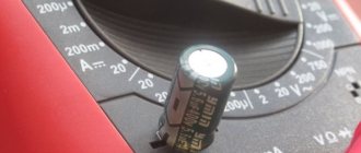
Checking the performance of capacitors
To test capacitors, use a capacitance meter. It can be made either as a separate device or as part of a multimeter (tester). It’s easier to consider checking with a multimeter:
- First of all, it is necessary to de-energize the capacitor;
- further discharge it by short-circuiting the terminals;
- remove one of the terminals;
- switch the multimeter to the mode for measuring capacitance of capacitors;
- attach the probes to the terminals of the capacitor;
- read the capacity indicator from the screen.
The capacitance measurement mode on a multimeter can be displayed in different ways. Most have special Fcx sockets.
Before starting a capacitor test, it is recommended to manually (or automatically, depending on the model) switch the limit of the measured capacitance. Typically the maximum value is 100 µF, which is sufficient in most cases. There are other instruments that allow you to measure capacitance. They are made in the form of probes, tweezers or equipped with special connectors.
It is important to understand that the rating indicated on the capacitor body must correspond to the measured value. If this is not the case, then it should be replaced.
Supply voltage
Each microcontroller has a precisely defined supply voltage level at which the manufacturer guarantees its correct operation. Sometimes a microcontroller of the same type can be manufactured in 2 versions, differing in permissible supply voltages.
Typically, the maximum clock frequency range of a microcontroller is also related to the supply voltages.
The most common beginner mistakes:
- they do not filter the power line at all or only install filters on the output of the voltage stabilizer
- they place power filters away from the microcontroller
- they don't connect all the power inputs "because the circuit works that way"
- they don't connect power to the analog part "because I don't use the analog part"
Good practice for powering microcontrollers:
- Each Vcc (Vdd) power pin should be equipped with a 100 nF capacitor to ground, located as close to the microcontroller as possible
- A stabilizer with capacitors, the ratings of which you will find in its technical description, must guarantee stable power with the highest possible power consumption by the developed system
- connect power to the analog part even if you are not using it.
Replacement and selection of capacitor
If there is a capacitor similar to the burnt one, then it is enough to simply install it in place of the old one. Polarity does not play a role here.
Many people do not know which capacitors cannot be used to start an electric motor. Capacitors with polarity indications (electrolytic) must not be used. They are thermally destroyed when used in such circuits. As a rule, there are special ones for this purpose that are designed to work with alternating current and have no polarity, and also have special fastening and terminals for quick installation.
If the required rating is not available, then the easiest way is to connect several capacitors. This must be done in parallel, since with this type of connection the capacity will be total. At the same time, the maximum voltage for which they are designed to work does not increase. This connection diagram fully corresponds to the installation of a larger capacitor.
How to connect capacitors
In electrical engineering there are two main types of connecting parts - parallel and series. Capacitors can also be connected using any of the above methods. There is also a special one - a bridge circuit. It has its own area of use.
The circuit can have series and parallel connection of capacitors
Parallel connection of capacitors
In a parallel connection, all capacitors are combined by two nodes. To connect capacitors in parallel, we twist their legs in pairs, crimp them with pliers, and then solder them. Some capacitors have large bodies (banks) and small terminals. In this case, we use wires (as in the figure below).
This is what a parallel connection of capacitors physically looks like
If the capacitors are electrolytic, pay attention to the polarity. They should be marked with “+” or “-“. When connecting them in parallel, we connect the terminals of the same name - plus to plus, minus to minus.
Calculation of total capacity
When capacitors are connected in parallel, their nominal capacity is added together. Simply sum up the values of all connected elements, no matter how many there are. Two, three, five, thirty. We just add it up. But make sure that the dimensions match. For example, we will add in microfarads. This means that we convert all values into microfarads and only then sum them up.
Calculation of capacitance when connecting capacitors in parallel
When is parallel connection of capacitors used in practice? For example, when you need to replace a “dry” or burnt one, but the required denomination is not available and there is no time or no opportunity to run to the store. In this case, we select from those available. In total they should give the required value. We check all of them for functionality and connect them according to the above principle.
Calculation example
For example, we connected two capacitors in parallel - 8 μF and 12 μF. Following the formula, we simply add up their denominations. We get 8 µF + 12 µF = 20 µF. This will be the total capacity in this case.
An example of calculating capacitors for parallel connection
Always check the polarity carefully!
| Incorrect connection of the capacitor may cause damage, short circuit or explosion! |
When selecting capacitors, you need to select elements with the appropriate operating voltage, and remember to connect them correctly.
We conducted the following capacitor misconnection experiment under safe, controlled conditions. Don't do this yourself! The photo below shows what happens to a capacitor whose voltage is inversely proportional.
And by the way, think about it, what would happen if we connected 20 of these capacitors, and when turned on they all exploded? Below are photos before and after turning on the power:
| Running capacitor | Incorrectly connected capacitor |
It happens that a capacitor may stop working over time. A non-working capacitor can be identified by eye; it is bursting, the cup seems to swell. Larger capacitors are equipped with safety mechanisms in the form of slots in the upper part.
These slots act as a safety valve that opens when internal pressure rises before an explosion occurs. Above you see an electrolytic capacitor in which such a safety mechanism has tripped.