Circuit design is a modern and rather complex science with a high threshold for entry in terms of qualification level. Some people try to master it on their own, but, as a rule, it doesn’t go beyond assembling simple electronic circuits and repairing household appliances. To successfully assemble boards on your own, applicants for the title of amateur radio operator must have basic knowledge of physics, as well as be able to correctly determine the rating of a particular electronic component.
If the area of the capacitor or resistor allows, then the main characteristics of the product are almost always marked on such elements, otherwise a novice designer and assembler of devices may encounter insurmountable difficulties. This article will talk about how to find out the capacitance of an SMD capacitor, as well as ways to determine other parameters of this type of product.
What are SMD capacitors
What are SMD capacitors and what are they for?
Many electronic components are large in size and are mounted on the board using wire taps or wide legs, similar to microcircuits. For reliable fixation, the contact elements of such parts are installed in specially made holes, in which they are coated with molten solder to ensure high-quality electrical contact.
Standard installation of radio components
If the power dissipation of resistors or the value of capacitors is too small, then there is no need to make such a product too bulky. Installing elements of this type by drilling the board would force electronic circuit designers to allocate an unreasonably large area of the printed circuit for their installation. The logical solution to this problem is to use SMD components.
SMD technology (Surface Mounted Device) is a method of installing electronic parts without drilling the board. Such a component is simply soldered on one side of the surface, thereby saving significant area without reducing its strength by the presence of a large number of micro-holes.
Note! The surface mounting method can be used to install not only capacitors, but also resistors, transistors and microcircuits.
The use of SMD components allows for maximum optimization of the arrangement of parts on the board. Thanks to the use of this technology, circuits for complex devices can be manufactured in relatively small sizes, which is especially important when designing mobile products.
Soldering printed circuit boards
In this case, it is necessary to apply less effort than in the previous one, since here the board holes play a good role as a retainer for parts.
But experience is important here too. Often the result of the work of beginners is that the circuit begins to look like one large and continuous conductor. But this is not a difficult task, so after a little training the result will be at a decent level. Now let's figure out how SMD installation occurs in this case. Initially, the soldering iron tip and solder are simultaneously brought to the soldering site. Moreover, both the processed pins and the board must heat up. It is necessary to hold the tip until the solder evenly covers the entire contact area. Then it can be drawn in a semicircle around the treated area. In this case, the solder should move in the opposite direction. We ensure that it is evenly distributed over the entire contact area. After this, remove the solder. And the last step is to quickly remove the tip from the soldering site. We wait until the solder takes its final shape and hardens. This is how SMD installation is carried out in this case. The printed circuit board at the first attempts will not look so great, but over time you can learn to make it at such a level that you cannot distinguish it from the factory version.
Types of SMD capacitors
Every radio amateur needs to understand the types of capacitors mounted using the surface-mount method. Such products may differ not only in capacity, but also in voltage, so ignoring the conditions for using parts can lead to their failure.
You might be interested in Color rendering measurement coefficient
Electrolytic components
Electrolytic SMD capacitors do not differ fundamentally from standard products. Such electronic components most often take the form of barrels, in which a thin metal rolled into a cylinder is located under an aluminum housing, and a solid or liquid electrolyte is located between it.
Electrolytic SMD capacitors
The main difference between such a part and a standard electrolytic cell is that its contacts are mounted on a flat dielectric substrate. Such products are very reliable in operation, especially convenient when it is necessary to install a new product with minimal time investment. In addition, during soldering the product does not overheat, which is very important for electrolytic capacitors.
Ceramic components
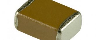
In ceramic elements, porcelain or similar inorganic materials are used as a dielectric. The main advantage of such products is their resistance to high temperatures and the ability to produce products of extremely small sizes.
Important! SMD ceramic capacitors are also installed by soldering onto a printed circuit board.
Visually, such an element, as a rule, resembles a small brick to which contact pads are soldered at the ends.
Ceramic SMD capacitors
Unlike radio components of standard sizes, SMD elements of small size are first glued to the board, and only then the leads are soldered. In production, ceramic products of this type are installed by special automatic machines.
Marking of tantalum SMD capacitors
Tantalum SMD capacitors are resistant to increased mechanical loads. Such products can also be made in the form of a small parallelepiped, to which contact leads are soldered on the sides. Tantalum is a very durable metal with high ductility. Foil made of this material can have a thickness of hundredths of a millimeter.
For your information! Due to the presence of certain physical properties based on tantalum, it is possible to produce radio components of the highest precision.
Tantalum capacitors
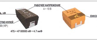
Tantalum capacitors, as a rule, have small housing sizes, so it is not always possible to apply full markings to products made in an “A” size housing. Knowing the designation features of radio components of this type, you can easily determine the rating of the product. The maximum permissible voltage in volts for tantalum products is indicated in Latin letters:
- G - 4;
- J - 6.3;
- A - 10;
- C - 16;
- D - 20;
- E - 25;
- V - 35;
- T - 50.
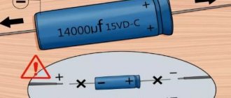
Note! The capacitance of products is indicated in microfarads after the letter “μ”, and the positive contact is indicated with a thick line.
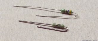
RESISTORS. COLOR MARKING
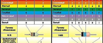
Color marking is applied in the form of 4.5 or 6 color rings. The marking rings must be shifted to one of the terminals, or the width of the first character ring must be twice as large as the others, which is not always maintained in practice. Instead of color rings, there may be color dots. The marking principle is the same.
Color coding of resistors
JUMPERS AND RESISTORS WITH “ZERO” RESISTANCE.
Many companies produce special wires – Jumper Wire – with standardized resistance and diameter (0.6 mm, 08 mm) and resistors with “zero” resistance as fuse links or jumpers. Resistors are available in a standard cylindrical package with flexible leads (Zero-Ohm) or in a standard surface mount package (Jumper Chip). The actual resistance values of such resistors lie in the range of units or tens of milliohms (- 0.005...0.05 Ohm). In cylindrical housings, the marking is carried out with a black ring in the middle; in surface-mount housings (0603,0805,1206...), there is usually no marking, or the code “000” is applied.
Designation of SMD capacitors
To establish the value of an SMD capacitor, you will need to carefully study its markings. On large-sized elements, as a rule, basic information is applied not only about its denomination, but also the manufacturer’s logo is indicated.
You may be interested in this: Learning to read electrical diagrams
When figuring out the parameters of small bricks, you will have to spend a certain amount of time, because even if the necessary information is available on their body, it is unlikely that you will be able to see the symbols on their surface with the naked eye.
Important! Depending on the type of capacitor, the designations of its parameters may also differ significantly, which must be taken into account in the work.
Marking of ceramic SMD capacitors
Small ceramic SMD capacitors are marked with an alphanumeric code consisting of 3 characters. The first indicates the minimum operating temperature, for example:
- Z - from 10 °C;
- Y - from −30 °С;
- X - from 55 °C.
Marking of SMD capacitors
The second symbol indicates the upper limit of heating of the radio component:
- 2 - up to 45 °C;
- 4 - up to 65 °C;
- 5 - up to 85 °C;
- 6 - up to 105 °C;
- 7 - up to 125 °C;
- 8 - up to 150 °C;
- 9 - up to 200 °C.
The third character indicates the accuracy of the electronic component:
- A - up to ± 1.0%;
- B - up to ± 1.5%;
- C - up to ± 2.2%;
- D - up to ± 3.3%;
- E - up to ± 4.7%;
- F - up to ± 7.5%;
- P - up to ± 10%;
- R - up to ± 15%;
- S - up to ± 22%;
- T - up to ± 33%;
- U - up to ± 56%;
- V - up to ± 82%.
The capacity of small ceramic SMD capacitors is indicated in picofarads. To save the area of a small radio element, the main mantissa number is encoded in a letter of the Latin alphabet. The table below provides a complete list of such designations.
Table with encoded characters
After the number, the multiplier is indicated, for example, the designation on a ceramic capacitor X3 means that the capacitor has a capacity of 7.5 * 10 ^ 3 Pf.
Note! The code indicating the capacity of a ceramic SMD capacitor may be preceded by a Latin letter, which indicates the brand of the manufacturer of the electronic component.
If the area of this type of ceramic capacitor is large enough, then the dielectric type can be displayed on it. For this purpose the following are used:
- NP0. The dielectric constant of such an element is at an extremely low level. The main advantage of components of this type is their good resistance to sudden temperature changes. The disadvantage of elements that use this type of dielectric is their high price;
- X7R. Average quality dielectric. Products that use this type of insulator do not have excellent breakdown resistance characteristics, but in the average temperature range they are able to work significantly longer than many more expensive elements;
- Z5U. A dielectric with high electrical permeability values, but the downside of this indicator is that the capacitance error is too large;
- Y5V. The insulating material has approximately the same characteristics as Z5U. In terms of cost, this dielectric is the cheapest, so electrical components made on its basis are sold at the lowest prices.
You might be interested in this All about stray currents
Burnt SMD capacitor
Considering all of the above, you can be sure that if the SMD capacitor has not burned or changed the color of the surface for other reasons, then you can always determine its value by the markings on its body.
Marking of electrolytic SMD capacitors
Electrolytic capacitors of this type, as a rule, are relatively large in size, so many parameters of such elements are indicated without encryption. That is, the maximum voltage value will be indicated by the number and letter “V”, and the capacitance will be mF.
Marking of electrolytic SMD capacitors
In some cases, the SMD value of an electrolytic type capacitor may also be encoded. Typically, 4 characters (one letter and 3 numbers) are used for this purpose. The first character is the voltage in volts:
- e 2.5;
- G 4;
- J 6.3;
- A 10;
- C 16;
- D 20;
- E 25;
- V 35;
- H 50.
Note! The next three digits encode information about the capacitance of the capacitor (2 digits + multiplier).
Thus, even very small electrolytic SMD capacitors can be marked with information about the main parameters of the product.
How to determine the capacitance, rating and voltage of SMD capacitors
Above, detailed information was provided on how to correctly determine the rating of SMD capacitors by marking. The main difficulty in performing such an operation is that the characters may be so small that they cannot be identified with the naked eye. In such a situation, it is recommended to use a magnifying glass or any other magnifying device with a suitable magnification, as well as install high-quality lighting in the place where such studies are carried out.
Radio amateur magnifier
Note! Sometimes the markings on the surface of the radio element are not readable or are completely missing, so every radio amateur should know how to determine the capacitance of an electrolytic capacitor without markings. To perform such work, you cannot do without a special measuring device.
How to determine the capacitance of an SMD capacitor without markings using a device
To obtain correct indicators, before starting to measure the capacitance of the capacitor, the radioelement must be completely discharged.
The voltage limit is measured on a capacitor, which is installed in an electronic circuit where the element can be safely connected to electrical voltage. After turning off the current source, measure the voltage at the contacts of the radio component. The resulting value in volts should be multiplied by 1.5 to obtain the exact value of this parameter.
Voltage can be measured with a cheap multimeter
SMD capacitors are very convenient for self-assembly of various circuits, and during automatic installation, thanks to them, it is possible to achieve maximum compactness in the arrangement of radio components. Knowing the principles of deciphering the designation of such elements, you can design and assemble even complex devices at home without any difficulty.