§ 99. Induction devices
Device. The induction device consists of two stationary electromagnets 2 and 3 (Fig. 329) and a movable aluminum disk 4, mounted on the same axis with the arrow.
When alternating currents I1 and I2 pass through the coils of electromagnets, two magnetic fluxes F1 and F2 are created, shifted relative to one another in phase, which penetrate the disk. These flows, when changing, induce eddy currents Iв1 and Iв2 in the disk. As a result of the interaction of eddy currents with the magnetic fields of both electromagnets (current Iв1 with flow Ф2 and current Iв2 with flow Ф1), a torque M arises, under the influence of which the moving part of the device rotates. The counteracting moment in voltmeters, ammeters and wattmeters is created by a spiral spring 1 or stretch marks.
The average value of the torque M over the period is proportional to the product of the effective values of magnetic fluxes F1 and F2 and the sine of the phase shift angle? between these threads:
M = c1?1?2 sin? (102)
where c1 is a constant value for the device.
Rice. 329. Design of an induction measuring mechanism
To obtain the greatest value of torque, the phase shift angle between the flows is set to 90° by including additional active and reactive resistances in the coil circuits. Under this condition, the average torque in voltmeters and ammeters will be proportional to the product of the effective values of the currents I1 and I2 flowing through the coils of the electromagnets. This value will also determine the angle of rotation of the arrow:
? = kI1I2 (103)
In wattmeters? = kUI cos ? = kP, since the current I1 is proportional to the current I in the circuit, I2 is proportional to the voltage U, and the angle ? equal to an angle of 90° - ?.
Application. Induction devices, as well as electrodynamic ones, can be used as an ammeter, voltmeter and wattmeter. The electromagnet coils are turned on in these cases in the same way as the coils of an electrodynamic device (see Fig. 327).
The advantages of induction devices are high resistance to overloads, high torque and low sensitivity to external magnetic fields. Disadvantages include relatively low accuracy and dependence of readings on alternating current frequency and temperature influences.
Induction devices are used mainly as wattmeters and electricity meters in industrial installations and on AC electric locomotives.
3.3. MAGNETOELECTRIC SYSTEM
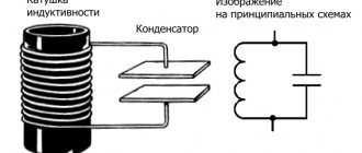
The devices of this system (Fig. 3.3.1) contain a permanent magnet - 1, to which poles - 2 are attached. In the interpolar space there is a steel cylinder - 3 with a frame glued to it - 4. Current is supplied to the frame through two spiral springs -5. The operating principle of the device is based on the interaction of the current in the frame with the magnetic field of the poles.
This interaction causes a torque, under the influence of which the frame and along with it the cylinder will rotate at an angle. The coil spring in turn produces a counter torque. Since torque is proportional to current,
, and the counteracting moment is proportional to the angle of twist of the springs, then we can write:
where k and D are proportionality coefficients. From what has been written it follows that the angle of rotation of the frame
Where
— sensitivity of the device to current, determined by the number of scale divisions corresponding to a unit of current; CI is a constant current, known for each device. Consequently, the measured current can be determined by the product of the rotation angle (measured on a scale) and the current constant CI. The advantages of this system include high accuracy and sensitivity, low energy consumption. Disadvantages include the complexity of the design, sensitivity to overloads, and the ability to measure only direct current (without additional means).
H.2. CLASSIFICATION OF ELECTRICAL DEVICES
Electrical measuring instruments can be classified according to the following criteria: measurement method; the type of quantity being measured; type of current; degree of accuracy; operating principle
. There are two measurement methods: 1) the direct assessment method, which consists in the fact that during the measurement process the measured value is immediately assessed; 2) the comparison method, or the zero method, which serves as the basis for the operation of comparison devices: bridges, compensators. Electrical measuring instruments are distinguished by the type of quantity being measured: for measuring voltage (voltmeters, millivoltmeters, galvanometers); for measuring current (ammeters, milliammeters, galvanometers); for measuring power (wattmeters); for energy measurement (electric meters); for measuring the phase shift angle (phase meters); for measuring current frequency (frequency meters); for measuring resistance (ohmmeters), etc. Depending on the type of current being measured, devices of direct, alternating single-phase and alternating three-phase current are distinguished. According to the degree of accuracy, devices are divided into the following accuracy classes: 0.05; 0.1; 0.2; 0.5; 1.0; 1.5; 2.5; and 4.0. The accuracy class should not exceed the given relative error of the device, which is determined by the formula:
where A is the readings of the device being verified; A0 - readings of the reference device; Amax - maximum value of the measured value (measurement limit). Depending on the principle of operation, systems of electrical measuring instruments are distinguished. Devices of the same system have the same operating principle. There are the following main instrument systems: magnetoelectric, electromagnetic, electrodynamic, induction.
Is induction heating economical?
Remember that the induction system is an electric type of heating, so it is very difficult to call it cheap. Absolutely any fuel options can compete with such a system in cost.
In order to make this a more economical form of home heating, the best option is to install a heat accumulator. This will help to run electric heating only at night, and during the daytime the already accumulated heat will work.
At night, there is generally a reduced electricity tariff.
Online and in any store they will tell you that the beneficial effect of an induction heating boiler is 100%.
Of course, this is true, because any electric boiler converts electrical energy into heat. However, few people take into account the fact that part of the heating remains in the room where the boiler is installed.
Regarding heat distribution, this heating option is also considered not the most economical and correct. Radiators are installed from the induction boiler, which create heat only for the air that is in the upper part of the room, leaving your feet cold.
The most preferable from this side is a warm floor, in which the cold air remains at the top. In order to accurately select the right option, you need to familiarize yourself with the diagrams and calculations of induction heating.
3.5. ELECTRODYNAMIC SYSTEM
This system consists of two coils (Fig. 3.5.1), one of which is fixed and the other is movable. Both coils are connected to the network, and the interaction of their magnetic fields causes the moving coil to rotate relative to the stationary one.
From Eq.
It can be seen that the scale of the electrodynamic system has a quadratic character. To eliminate this drawback, the geometric dimensions of the coils are selected in such a way as to obtain a scale close to uniform. These systems are most often used to measure power, i.e. as wattmeters, then:
In this case, the wattmeter scale is uniform. The main advantage of the device is its high measurement accuracy. Disadvantages include low overload capacity, low sensitivity to small signals, and a noticeable influence of external magnetic fields.
Induction system device
The electric meter contains a magnetic circuit - 1 of complex configuration, on which two coils are placed; voltage – 2 and current – 3. An aluminum disk – 4 with an axis of rotation – 5 is placed between the poles of the electromagnet.
The torque acting on the disk is determined by the expression:
Mvr = ki ΦU ΦI sinψ
where ФU is part of the magnetic flux created by the voltage winding and passing through the meter disk; ФI – magnetic flux created by the current winding; ψ – shift angle between ФU and ФI. Magnetic flux ФU is proportional to voltage ФU = k2 U. Magnetic flux ФI is proportional to current ФI = k3 I.
In order for the meter to respond to active energy, the following condition must be met:
sinψ = cosφ
In this case, the torque is proportional to the active power of the load:
Mvr = k1 k2 k3 UI cosφ = k4 P
The counteracting torque is created by the brake magnet – 6 and is proportional to the speed of rotation of the disk:
In steady state, Mvr = Mpr, the disk rotates at a constant speed. We equate the last two equations and solve the resulting equation with respect to the angle of rotation of the disk:
Thus, the angle of rotation of the counter disk is proportional to the active energy. Consequently, the number of disk revolutions n is also proportional to the active energy.
20) Measuring current transformers.
Current transformer
- a transformer, the primary winding of which is connected to a current source, and the secondary winding is closed to measuring or protective devices that have low internal resistance.
Instrument current transformer
- a transformer designed to convert current to a value convenient for measurement. The primary winding of the current transformer is connected in series to the circuit with the measured alternating current, and the measuring instruments are connected to the secondary winding. The current flowing through the secondary winding of a current transformer is proportional to the current flowing in its primary winding.
Current transformers are widely used for measuring electric current and in relay protection devices for electrical power systems, and therefore they are subject to high accuracy requirements. Current transformers provide measurement safety by isolating the measuring circuits from the high voltage primary circuit, often hundreds of kilovolts.
Connection diagrams for measuring current transformers
In three-phase networks with an isolated neutral (networks with a voltage of 6-10-35 kV), current transformers are often installed on only two phases (usually phases A and C). This is due to the absence of a neutral wire in 6-35 kV networks and information about the current in a phase with a missing current transformer can be easily obtained by measuring the current in two phases. In networks with a solidly grounded neutral (networks up to 1000V) or an effectively grounded neutral (networks with voltages of 110 kV and above), current transformers must be installed in all three phases.
In the case of installation in three phases, the secondary windings of the current transformers are connected according to the “Star” circuit (Fig. 1), in the case of two phases - “Partial star” (Fig. 2). For differential protection of power transformers with electromechanical relays, the transformers are connected according to the “Triangle” circuit (to protect the transformer winding connected in a star when connecting the protected transformer “triangle-star”, which is necessary to compensate for the phase shift of secondary currents in order to reduce the unbalance current). To save measuring elements in protection circuits, the “Current phase difference” circuit is sometimes used (should not be used for protection against short circuits behind power transformers with a delta-star connection).
Important parameters of current transformers are the transformation ratio and accuracy class.
Source
3.7. CURRENT AND VOLTAGE MEASUREMENT
Current is measured with a device called an ammeter. There are four schemes for connecting an ammeter to a circuit. The first two (Fig. 3.7.1) are designed to measure direct current, and the second two circuits are designed to measure alternating current.
The second and fourth schemes are used in cases where the rated data of the ammeter is less than the measured current value. In this case, when determining the true value of the current, the conversion coefficient must be taken into account:
where Iist is the true current value, Imeas is the measured current value, kpr is the conversion coefficient. Voltage is measured with a voltmeter. Here, four different device connection schemes are also possible (Fig. 3.7.2).
These circuits also use methods to extend the voltage measurement limits (second and fourth circuits).