General information about transformers
A transformer is an electromagnetic device that converts alternating current with a change in voltage value.
The operating principle of the device involves the use of electromagnetic induction. The device consists of the following main elements:
- primary and secondary windings;
- the core around which the windings are wound.
Transformer operating principle
The change in characteristics is achieved due to different numbers of turns in the input and output windings.
The current in the output coil is excited by the creation of magnetic flux when voltage is applied to the input contacts.
Calculation of a pulse transformer of a push-pull converter
The advantage of push-pull converters is their simplicity and the ability to increase power. In a properly designed push-pull converter, a constant current passes through the winding, so there is no strong core bias. This allows you to use a full magnetization reversal cycle and get maximum power. Since it is performed on a ferrite core, the calculation of the output voltage of the transformer is similar to a conventional toroidal one.
You can simplify the transformer calculation options by using special calculation calculators, which are offered by some online resources. One has only to enter the desired data, and the machine will provide the necessary parameters of the planned electromagnetic device.
Transformer device
What if the coils are different? Then you can convert the voltage from one value to another. This is how a transformer works. A transformer converts voltage from the primary winding to a different voltage on the secondary winding.
The transformer only works with alternating, pulsed or any other current whose value changes over time.
A transformer converts current and voltage, but it does not allow increasing power. On the contrary, due to heating it takes a little power. And despite this, its efficiency can reach up to 99%.
Alternative method for dimensions
The approximate parameters of the transformer, based on the available core, can be determined in another way, and then conclusions can be drawn about the possibility of further use.
Knowing the cross-sectional area of the magnetic circuit in square centimeters, you can estimate the maximum power that this converter is capable of providing:
PG=S2
It should be borne in mind that this power is dimensional, and the real one will have a smaller value:
P=0.8 PG
Usually, provided that the calculated power matches the required one, the primary winding connected to the 220 V network can be left untouched, recalculating only the parameters at the outputs.
Transformer operating principle
The operating principle of the transformer is based on the phenomenon of electromagnetic induction.
If an alternating voltage U1 is applied to the primary winding, then an alternating current Io will flow through the turns of the winding, which will create an alternating magnetic field around the winding and in the magnetic core. The magnetic field forms a magnetic flux Фo, which, passing through the magnetic circuit, crosses the turns of the primary and secondary windings and induces (induces) alternating emfs in them - e1 and e2. And if a voltmeter is connected to the terminals of the secondary winding, it will show the presence of output voltage U2, which will be approximately equal to the induced emf e2.
When a load, for example an incandescent lamp, is connected to the secondary winding, a current I1 arises in the primary winding, forming an alternating magnetic flux F1 in the magnetic circuit, changing at the same frequency as the current I1. Under the influence of an alternating magnetic flux, a current I2 arises in the secondary winding circuit, which in turn creates a counteracting magnetic flux F2 according to Lenz’s law, tending to demagnetize the magnetic flux generating it.
As a result of the demagnetizing effect of the F2 flux, a magnetic flux Фo is established in the magnetic circuit equal to the difference between the F1 and F2 fluxes and being part of the F1 flux, i.e.
The resulting magnetic flux Фo ensures the transfer of magnetic energy from the primary winding to the secondary winding and induces an electromotive force e2 in the secondary winding, under the influence of which current I2 flows in the secondary circuit. It is due to the presence of magnetic flux Фo that current I2 exists, which will be greater the greater Фo. But at the same time, the greater the current I2, the greater the counteracting flow F2 and, therefore, the less Fo.
From the above it follows that at certain values of the magnetic flux F1 and the resistance of the secondary winding and load, the corresponding values of the emf e2, current I2 and flux F2 are established, ensuring the equilibrium of magnetic fluxes in the magnetic circuit, expressed by the formula given above.
Thus, the difference between the flows Ф1 and Ф2 cannot be equal to zero, since in this case the main flow Фo would be absent, and without it the flow Ф2 and current I2 could not exist. Consequently, the magnetic flux Ф1, created by the primary current I1, is always greater than the magnetic flux Ф2, created by the secondary current I2.
The magnitude of the magnetic flux depends on the current creating it and on the number of turns of the winding through which it passes.
The voltage of the secondary winding depends on the ratio of the number of turns in the windings. With the same number of turns, the voltage on the secondary winding will be approximately equal to the voltage supplied to the primary winding, and such a transformer is called an isolation transformer.
If the secondary winding contains more turns than the primary, then the voltage developed in it will be greater than the voltage supplied to the primary winding, and such a transformer is called a step-up transformer.
If the secondary winding contains fewer turns than the primary, then its voltage will be less than the voltage supplied to the primary winding, and such a transformer is called a step-down transformer.
Hence. By selecting the number of turns of the windings, for a given input voltage U1, the desired output voltage U2 is obtained. To do this, they use special methods for calculating the parameters of transformers, with the help of which the windings are calculated, the cross-section of the wires is selected, the number of turns is determined, as well as the thickness and type of the magnetic core.
The transformer can only operate in alternating current circuits. If its primary winding is connected to a direct current source, then a magnetic flux is formed in the magnetic circuit, constant in time, in magnitude and direction. In this case, an alternating voltage will not be induced in the primary and secondary windings, and therefore, electrical energy will not be transferred from the primary circuit to the secondary. However, if a pulsating current flows in the primary winding of the transformer, then an alternating voltage will be induced in the secondary winding, the frequency of which will be equal to the ripple frequency of the current in the primary winding.
We recommend reading: DIY FM antenna for a music center
Calculation of a transformer for a semi-automatic welding machine
The semi-automatic welding machine is designed for welding with mechanical supply of a special welding wire instead of an electrode. The power source of such a device is also based on a powerful transformer. The calculation is based on the principle of its operation, the output of which should be 60 Volts at idle. It operates in short-circuited mode, so heating of its windings is normal. The calculation is also similar in principle, only in this case it is also worth taking into account the power during prolonged welding
Pdl = U2I2 (PR/100)0.5 *0.001.
The voltage and strength of one turn is measured in volts and it will be equal to E=Pdl0.095+0.55. Knowing these values, you can proceed to a full calculation.
What is the efficiency of a transformer and what does it depend on?
Efficiency (the full interpretation of this abbreviation) is the ratio of useful electricity to that supplied to the device.
In addition to energy, the efficiency indicator can be determined by calculation based on power indicators based on the ratio of the useful value to the total value. This characteristic is very important when choosing a device and determines the effectiveness of its use.
The magnitude of the efficiency depends on the energy losses that are allowed during the operation of the device. These losses are of the following types:
- electrical - in the conductors of the coils;
- magnetic - in the core material.
The magnitude of these losses when designing a device depends on the following factors:
- overall dimensions of the device and shape of the magnetic system;
- compactness of the coils;
- density of assembled sets of plates in the core;
- diameter of wire in coils.
Reducing losses in the unit is achieved during the design process of the device, using soft magnetic ferromagnetic materials for the manufacture of the core. Electrical steel is assembled into thin plates, insulated relative to each other by a special layer of applied varnish.
During operation, the efficiency of the device is determined by:
- applied load;
- dielectric medium - a substance used as a dielectric;
- uniformity of load supply;
- oil temperature in the unit;
- degree of heating of the coils and core.
If during operation the unit is constantly underloaded or the specified operating conditions are violated, in addition to the risk of failure, this leads to a decrease in the efficiency of the device.
Methods for determining efficiency
Transformer efficiency can be calculated using several methods. This value depends on the total power of the device, increasing with the increase in the specified indicator. The efficiency value ranges from 0.8 to 0.92 at power values from 10 to 300 kW.
Knowing the value of the maximum power, you can determine the efficiency value using special tables.
Direct measurement
The formula for calculating this indicator can be presented in several expressions:
ɳ = (Р2/Р1)х100% = (Р1 – ΔР)/Р1х100% = 1 – ΔР/Р1х100%,
- ɳ – efficiency value;
- P2 and P1 – respectively the value of useful and consumed network power;
- ΔР – the value of the total power losses.
From this formula it is clear that the value of the efficiency indicator cannot exceed one.
After a step-by-step transformation of the above formula, taking into account the use of the values of electric current, voltage and angle between the phases, the following relationship is obtained:
ɳ = U2хI2хcosφ2/ U2хI2хcosφ2 + Robm + Рс,
- U2 and I2 – respectively, the value of voltage and current in the secondary winding;
- Robm and Rs - the amount of losses in the windings and core.
The presented formula is contained in GOST, which describes the definition of this indicator.
Efficiency calculations
Determination by indirect method
For devices with high operating efficiency, with an efficiency value exceeding 0.96, accurate calculation is not always possible. Therefore, this value is determined using an indirect method, which involves assessing the power indicators in the primary coil, the secondary coil and the allowed losses.
Assessing the characteristics of the transformer, it should be noted the high efficiency of using this equipment, due to its design features.
Circuit design options
As we have already said, on the basis of these transformers it is possible to make many different devices yourself. Let's look at how to assemble a charger based on TS-160.
- We connect the mains power to terminals “1” and “1'” through a switch and a fuse rated for a current of 0.6 A.
- We connect terminals “2” and “2'” to each other.
- Pins “10” and “9'” are also connected to each other. By connecting these two windings in series, you can get an alternating voltage of 13 V and a current of 3.5 A. This is quite enough to charge the batteries.
- The voltage needs to be straightened. To do this, connect a rectifier (diode bridge) to terminals “9” and “10'”. You can use domestic devices D242, D244 with any letter index for it. For cooling, we must attach the diodes to radiators.
- In order to avoid charging with a pulsating current, it is advisable to install a capacitor (or several in parallel) with a capacity of at least 1000 μF after the diode bridge.
- It is also advisable to install an ammeter and a voltmeter to monitor the charging mode.
- To protect the secondary windings, a 3.5 amp fuse or similar device is needed.
- We install the entire structure in a safe housing and equip it with output wires with a cross-section of at least 3.5 mm and terminals.
We will be glad if you found our article interesting and practically useful. Old equipment is not only recycled metal, but also a source of useful parts. Work with pleasure...!
What is power factor
Several types of load occur in the alternating current circuit that enters the transformer. Each of them defines a parameter, which, depending on the load, can be active, reactive or a complete combination of the two).
Active resistance is calculated taking into account that the losses will be equal to the square of the current multiplied by the resistance. Accompanied by the release of heat. Reactive occurs without heat generation and load loss, calculated using the formulas of inductance and capacitance. The coefficient is, in the general sense of the word, the ratio between the active and passive components.
How to calculate the power factor of a transformer: formulas and mathematical calculations
It can be determined using a simple formula: the average values of modular active (MA) and total (VA) are divided.
In this case, the active is calculated as the multiplied parameters of voltage and current, multiplied by cosine phi. For reactive force, the formula is identical, but taking into account that instead of cosine, sine is taken. The total is calculated as the voltage times the force, equal to the root of the square of the active and reactive.
Table of volts per turn
In order not to constantly carry out calculations, you can use the table, which shows the average data of the windings depending on the power:
| Power, P | Section in cm2, S | Number of vit. /B, W | Power, P | Section in cm2, S | Number of vit. /B, W |
| 1 | 1.4 | 32 | 50 | 9.0 | 5.0 |
| 2 | 2.1 | 21 | 60 | 9.8 | 4.6 |
| 5 | 3.6 | 13 | 70 | 10.3 | 4.3 |
| 10 | 4.6 | 9.8 | 80 | 11.0 | 4.1 |
| 15 | 5.5 | 8.4 | 90 | 11.7 | 3.9 |
| 20 | 6.2 | 7.3 | 100 | 12.3 | 3.7 |
| 25 | 6.6 | 6.7 | 120 | 13.4 | 3.4 |
| 30 | 7.3 | 6.2 | 150 | 15.0 | 3.0 |
| 40 | 8.3 | 5.4 | 200 | 17.3 | 2.6 |
Transformer power concept
An AC transformer does not produce electrical energy, but only converts it in magnitude. Therefore, its power completely depends on its load (current consumption) of the secondary circuit. If there are several consumers, the total load that can be connected simultaneously must be taken into account. For AC circuits, the active and reactive nature of consumption is taken into account.
We recommend reading: Types of batteries: detailed classification of batteries by size, composition and other parameters
Active
This component of the characteristic is defined as the average instantaneous value over a certain period of time. For sinusoidal alternating current circuits, the value of the oscillation period is used as a period of time:
T=1/f,
where f is frequency.
The active part depends on the nature of the load, that is, on the phase shift between current and voltage and is determined by the formula:
P=i∙U∙cosϕ,
where ϕ is the phase shift angle.
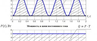
The active component of AC devices is expressed in Watts, as for DC circuits.
Reactive
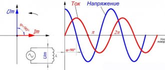
A reactive load differs from an active load in that during one period of voltage fluctuations, electrical energy is not actually consumed, but is returned. As a result of the fact that devices with large capacitance or inductance (electric motors) are connected to the power supply device, a phase shift occurs between the current and voltage.
The reactive component of consumption is determined by the expression:
Q= i∙U∙sinϕ
The unit of measurement is var (volt-ampere reactive).
Full
The total power of the transformer takes into account all consumed and returned energy and is found from the expression:
S= i∙U
All components are related by the relationship:
S2=P2+Q2.
The unit of measurement is VA (volt-ampere).
Apparent power equals active power only in the case of a fully active load.
Nominal
The rated power of the transformer takes into account the possibility of operation of the structure, taking into account the connection of consumers of different types, that is, it is similar to the full one. At the same time, proper operation of the device is guaranteed for the entire declared service life under the specified operating conditions.
Rated power, like total power, takes into account the active and reactive nature of consumption, which can change during operation.
Expressed in volt-amperes.
Methodology for calculating transformer power
When calculating the power transformer of the supply substation, the average daily load and the duration of the period of maximum consumption are taken into account. In this case, the following ratio should be taken into account:
Snom≥∑Pmax
The peak consumption mode must also take into account the exposure time, since with short-term bursts (up to 1 hour), the device will operate in an underloaded mode, which is not economically profitable.
In such cases, it is necessary to take into account the overload capacity of the structure, which depends on design features, ambient temperature and cooling conditions. This is dictated by the conditions of permissible heating of the constituent elements (windings, switching circuits).
The concept of load factor defines the ratio of average daily and maximum consumption of electrical energy. The load factor is always less than one. Its value is related to the requirements for the reliability of power supply. The lower the required reliability, the more the coefficient can approach unity.
According to the cross section of the core
An electromagnetic device has a core with a pair of wires or several windings. This component of the device is responsible for the active induction increase in the magnetic field level. Among other things, the device promotes the efficient transfer of energy from the primary winding to the secondary winding through a magnetic field that is concentrated in the inner part of the core.
The parameters of the core determine the overall transformer power, which exceeds the electrical power.
The calculation formula for this relationship is:
So x Sc = 100 x Pr / (2.22 x Bs x A x F x Ko x Kc), where
- Sо - indicators of the core window area;
- Sc is the cross-sectional area of the core;
- Рг - overall power;
- Bс - magnetic induction inside the core;
- A is the current density in the conductors on the windings;
- F—alternating current frequency indicators;
- Ko is the window fill factor;
- Kc is the core fill factor.
The transformer power indicators are equal to the load level on the secondary winding and the power consumption from the network on the primary winding.
The most common types of transformers are produced using W-shaped and U-shaped cores.
By load
When choosing a transformer, several basic parameters are taken into account, presented:
- category of electrical supply;
- overload capacity;
- scale of standard power of devices;
- load distribution graph.
Currently, the typical transformer power is standardized.
Transformer options
To calculate the power connected to a transformer device, it is necessary to collect and analyze data on all connected consumers. For example, if there is a purely active load represented by incandescent lamps or heating elements, it is sufficient to use transformers with power ratings of 250 kVA.
In electrical supply systems, the transformer power indicators of the devices must ensure stable power supply to all electricity consumers.
Connection diagram
All devices of type TS (TSSh) - 160 (170) are connected in the same way. We are not considering the option with 127 V networks, since this voltage has not been used in the network for a long time.
- The 110 V primary windings, according to the table above, are connected in series to each other.
- We remove the necessary voltage from the secondary windings. For devices with two coils of the TC series, we connect the coils in parallel to increase the current.
- If there is a need for bipolar power supply, then the secondary windings are connected in series, and the neutral wire is removed from the point of their connection.
Important! When connecting windings in series or parallel, be careful not to make the connection out of phase.
Calculation
There are several types of calculations used by professionals. For beginners, they are all quite complex, so we recommend the so-called simplified version. It is based on four formulas.
The transformer allows you to reduce the voltage to the required parameters.
Formula of the law of transformation
So, the transformation law is determined by the following formula:
U1/U2=n1/n2, where:
- U1 – voltage on the primary winding,
- U2 – on the secondary,
- n1 – number of turns on the primary winding,
- n2 – on the secondary.
We recommend reading: Do-it-yourself repair of PC power supplies: step-by-step pinout, starting the power supply from a computer
Since it is the mains transformer that is being disassembled, the voltage on the primary winding will be 220 volts. The voltage on the secondary winding is the parameter you need. For ease of calculation, we take it equal to 22 volts. That is, in this case the transformation coefficient will be equal to 10. Hence the number of turns. If there are 220 of them on the primary winding, then 22 on the secondary winding.
We advise you to study the Resanta Voltage Stabilizer
Imagine that the device that will be connected through a transformer consumes a load of 1 A. That is, this parameter acts on the secondary winding. This means that a load of 0.1 A will act on the primary, because the voltage and current are in inverse proportion.
But power, on the contrary, is directly dependent. Therefore, the power on the primary winding will be: 220×0.1=22 W, on the secondary winding: 22×1=22 W. It turns out that the power on the two windings is the same.
As for the number of turns, calculating them per volt is not difficult. In principle, this can be done at random. For example, wind ten turns on the primary winding, check the voltage on it and divide the result by ten. If the indicator matches the output voltage you require, then you have hit the bull’s eye. If the voltage is reduced, then the number of turns will have to be increased, and vice versa.
And one more nuance. Experts recommend winding turns with a small margin. The thing is that there are always voltage losses on the windings themselves that need to be compensated. For example, if you need an output voltage of 12 volts, then the number of turns is calculated based on a voltage of 17-18 V. That is, losses are compensated.
Core area
As mentioned above, the power of a power supply is the sum of the powers of all its secondary windings. This is the basis for choosing the core itself and its area. The formula is:
S=1.15 * √P
In this formula, the power is set in watts, and the area is obtained in square centimeters. If the core itself has an W-shaped design, then the cross-section is taken from the middle rod.
Types of cores for transformers.
Number of turns in the primary winding
The following formula is used here:
n=50*U1/S, it is clear that U1 is equal to 220 V.
By the way, the empirical coefficient “50” may change. For example, so that the power supply does not go into saturation and thereby does not create unnecessary interference (electromagnetic), it is better to use the coefficient “60” in the calculation. True, this will increase the number of turns of the winding, the transformer will become a little larger in size, but at the same time losses will be reduced, and, therefore, the operating mode of the power supply will become easier
Wire size
And the last fourth formula concerns the cross-section of the copper wire used in the windings.
d=0.8*√I, where d is the diameter of the wire, and “I” is the current strength in the winding.
The calculated diameter must also be rounded to a standard value.
So, here are four formulas used to select a current transformer
It doesn’t matter here whether you buy a ready-made device or assemble it yourself. But keep in mind that this calculation is only suitable for a network transformer that will operate from a network of 220 V and 50 Hz
Transformer designation on the diagram.
For high-frequency devices, completely different formulas are used, where the losses of the current transformer will have to be calculated. True, the formula for the transformation coefficient is exactly the same. By the way, a ferromagnetic core is installed in these devices.
Typical parameter calculation
Quite often, radio amateurs use a simplified method when calculating a transformer. It allows you to perform calculations at home without using quantities that are difficult to know. But it’s easier to use an online calculator ready for calculating a transformer. In order to use such a calculator, you will need to know some data, namely:
- voltage of the primary and secondary windings;
- core dimensions;
- plate thickness.
After entering them, you will need to click the “Calculate” button or something similar in name and wait for the result.
Rod type magnetic core
If it is not possible to calculate on a calculator, performing such an operation yourself is not difficult and manually. To do this, you will need to determine the voltage at the output of the secondary winding U2 and the required power Po. The calculation proceeds as follows:
- The load current is calculated: In=Po/U2, A.
- The value of the secondary winding current is calculated: I2 = 1.5*In, A.
- The power of the secondary winding is determined: P2 = U2*I2, W.
- The total power of the device is found: Pt = 1.25*P2, W.
- The current strength of the primary winding is calculated: I1 = Pt/U1, A.
- The required cross-section of the magnetic circuit is found: S = 1.3*√ Pt, cm².
It should be noted that if a device is designed with several terminals in the secondary winding, then in the fourth point all powers are summed up and their result is substituted instead of P2.
After the first stage is completed, proceed to the next stage of calculation. The number of turns in the primary winding is determined by the formula: K1 = 50*U1/S. And the number of turns of the secondary winding is determined by the expression K2= 55* U2/S, where:
- U1 - voltage of the primary winding, V.
- S—core area, cm².
- K1, K2 - number of turns in windings, pcs.
It remains to calculate the diameter of the wound wire. It is equal to D = 0.632*√ I, where:
- d — wire diameter, mm.
- I is the winding current of the calculated coil, A.
When selecting a magnetic core, you should maintain a ratio of 1 to 2 of the width of the core to its thickness. At the end of the calculation, the fillability is checked, i.e. whether the winding will fit on the frame. To do this, the window area is calculated using the formula: So = 50*Pt, mm2.
Autotransformer Features
Autotransformers are calculated similarly to simple transformers, only the core is determined not for the entire power, but for the power of the voltage difference.
For example, the power of the magnetic circuit is 250 W, the input is 220 volts, and the output needs to be 240 volts. The voltage difference is 20 V, with a power of 250 W the current will be 12.5 A. This current value corresponds to a power of 12.5 * 240 = 3000 W. The mains current consumption is 12.5+250/220=13.64A, which exactly corresponds to 3000W=220V*13.64A. The transformer has one 240 V winding with a 220 V tap, which is connected to the network. The section between the outlet and the outlet is wound with a wire rated at 12.5A.
Thus, an autotransformer allows you to obtain significantly more output power than a transformer with the same core with a low transmission coefficient.
Toroidal type transformer
Toroidal transformers have a number of advantages over other types: smaller size, lighter weight and, at the same time, higher efficiency. At the same time, they are easily wound and rewound. Using an online calculator to calculate a toroidal transformer allows you not only to reduce the manufacturing time of the product, but also to experiment on the fly with different input data. The following data is used:
- input winding voltage, V;
- output winding voltage, V;
- output winding current, A;
- outer diameter of the torus, mm;
- internal diameter of the torus, mm;
- torus height, mm.
It should be noted that almost all online programs do not demonstrate particular accuracy when calculating pulse transformers. To obtain high accuracy, you can use specially developed programs, for example, Lite-CalcIT, or calculate manually. For independent calculations, use the following formulas:
- Output winding power: P2=I2*U2, W.
- Overall power: Pg=P2/Q, W. Where Q is the coefficient taken from the reference book (0.76−0.96).
- The actual cross-section of the “iron” at the location of the coil: Sch= ((Dd)*h)/2, mm2.
- Calculated cross-section of the “iron” at the location of the coil: Sw =√Pq/1.2, mm2
- Torus window area: Sfh=d*s* π/4, mm2.
- The value of the operating current of the input winding: I1=P2/(U1*Q*cosφ), A, where cosφ is a reference value (from 0.85 to 0.94).
- The wire cross-section is found separately for each winding from the expression: Sp = I/J, mm2., where J is the current density taken from the reference book (from 3 to 5).
- The number of turns in the windings is calculated separately for each coil: Wn=45*Un*(1-Y/100)/Bm* Sch pcs., where Y is a table value that depends on the total power of the output windings.
- It remains to find the output power and the calculation of the toroidal power transformer is considered completed. Pout = Bm*J*Kok*Kct* Sch* Sfh /0.901, where: Bm - magnetic induction, Kok - wire filling coefficient, Kct - iron filling coefficient.
All coefficient values are taken from the radio equipment reference book (REA). Thus, it is not difficult to carry out calculations manually, but you will need accuracy and access to reference data, so it is much easier to use online services.
Low power factor: causes and consequences
A low indicator leads to a maximum elimination of the energy component. Special devices are used for compensation, which reduce electricity consumption and increase the efficiency of the device.
Load losses in network elements
Loading leads to redistribution and reduction of the energy component. The voltage level drops, which causes significant overheating of the device. The consequence is loss of efficiency and performance, rapid failure of equipment.
The specialist minimizes load-type forces. This allows you to increase the starting torque of the device.