The specificity of the AC network leads to the fact that at a fixed moment in time the sinusoids of voltage and current at the receiver coincide only in the case of the so-called active load, which completely converts the current into heat or mechanical work. In practice, these are all kinds of electric heating devices, incandescent lamps, to some approximation, electric motors and electromagnets under load, and sound-reproducing equipment.
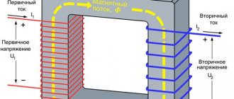
The situation changes completely if the load, which does not create mechanical work, has high inductance and low resistance. This is a typical case of an electric motor or transformer at idle. Connecting such a consumer to a direct current source would lead to a short circuit; here, nothing special will happen to the network, but the instantaneous current will lag behind the instantaneous voltage by about a quarter of a period. In the case of a purely capacitive load (if a capacitor is inserted into the socket), the current on it will, on the contrary, lead the voltage by the same quarter of a period.
Definition
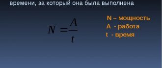
The load on an electrical circuit determines how much current flows through it. If the current is constant, then in most cases a resistor of a certain resistance can be defined as the load equivalent. Then the power is calculated using one of the formulas:
P=U*I
P=I2*R
P=U2/R
The same formula is used to determine the total power in an alternating current circuit.
The load is divided into two main types:
- Active is a resistive load, such as heating elements, incandescent lamps and the like.
- Reactive - it can be inductive (motors, starter coils, solenoids) and capacitive (capacitor units, etc.).
The latter only happens with alternating current, for example, in a sinusoidal current circuit, which is exactly what you have in your sockets. We will explain below what the difference between active and reactive energy is in simple language, so that the information becomes clear to novice electricians.
Payment for reactive power
Legislation in the field of electric power industry provides for a rather impressive set of references to the need to pay the consumer to the network organization for reactive power, however, in fact, such payment is not currently being made. Let's figure out why this happens. The power triangle, known to everyone since school, creatively reworked in the illustration for this article, suggests that total power consists of active power, that is, going to useful work, as well as reactive power, which, accordingly, does not go to useful work . Essentially, reactive power is loss. The greater the reactive power, the more energy the network organization must transfer in order for the consumer's electrical installations to perform useful work. Logically, the consumer must either compensate the network organization for the costs of transmitting “extra” power, or install reactive power compensators, which are not cheap at all. At first glance, the legislation is on the side of the network organization. The rules for the provision of services for the transmission of electrical energy indicate that:
- If necessary, the consumer is obliged to install equipment that provides reactive power regulation.
- The consumer is obliged to maintain the values of electric energy quality indicators at the balance sheet boundary, including observing the values of the ratio of active and reactive power consumption determined for individual power receiving devices (groups of power receiving devices).
- The network organization is obliged to determine the ratio of active and reactive power consumption for individual power receiving devices. The determination rules are established by the corresponding order of the Ministry of Energy of the Russian Federation.
- If the network organization detects a violation by the consumer of the ratio of active and reactive power, then: An act is drawn up.
- The consumer notifies the period during which he will install reactive power compensators.
- If there is no notification from the consumer, or compensators are not installed within the established time frame (no more than 6 months), an increasing factor is applied to the consumer in the tariff for electricity transmission services.
The size of the increasing coefficient is established in accordance with methodological guidelines approved by the federal executive body in the field of state regulation of tariffs.
When making technological connections, in the technical specifications for applicants, the network organization specifies the requirements for devices for monitoring and metering power quality, including the ratio of active and reactive power. The rules for retail electricity markets state that:
- The consumer's responsibility to ensure the functioning of reactive power compensation is an essential condition of the energy supply contract.
- The consumer is obliged to maintain, at the balance sheet boundary, the values of electric energy quality indicators, to comply with the values of the ratio of active and reactive power consumption for individual energy receiving devices.
Why, with such a detailed study of the issue of the consumer’s responsibilities to maintain the ratio of active and reactive power and pay the network organization for transmission services with an increasing factor in case of violation of this ratio, at present consumers actually do not pay extra for reactive power? It's simple.
Currently, increasing coefficients are established only for consumers connected to the networks of the unified national (all-Russian) electric grid.
That is, for consumers who do not have an agreement for the provision of electricity transmission services with PJSC FGC UES, a violation of the ratio of active and reactive power can be recorded, but it cannot be punished for this. As a result, in distribution networks, reactive power control is carried out only at the technological connection stage, where the network organization can include the installation of reactive power compensators in the technical conditions.
The meaning of reactive load
In an electrical circuit with a reactive load, the current phase and the voltage phase do not coincide in time. Depending on the nature of the connected equipment, the voltage either leads the current (in inductance) or lags behind it (in capacitance). Vector diagrams are used to describe issues. Here, the same direction of the voltage and current vector indicates the coincidence of phases. And if the vectors are depicted at a certain angle, then this is the advance or lag of the phase of the corresponding vector (voltage or current). Let's look at each of them.
In inductance, voltage always leads current. The “distance” between phases is measured in degrees, which is clearly illustrated in vector diagrams. The angle between the vectors is denoted by the Greek letter "Phi".
In an idealized inductance, the phase angle is 90 degrees. But in reality this is determined by the full load in the circuit, and in reality it cannot do without a resistive (active) component and a parasitic (in this case) capacitive component.
In a capacitor, the situation is the opposite - the current leads the voltage, because the inductance, when charging, consumes a large current, which decreases as it charges. Although it is more often said that voltage lags behind current.
To put it briefly and clearly, these shifts can be explained by the laws of commutation, according to which the voltage in a capacitor cannot change instantly, and the current in inductance cannot change.
Power triangle and cosine Phi
If you take the entire circuit, analyze its composition, phases of currents and voltages, then construct a vector diagram. After this, draw the active one along the horizontal axis, and the reactive one along the vertical axis and connect the ends of these vectors with the resulting vector - you get a triangle of powers.
It expresses the ratio of active and reactive power, and the vector connecting the ends of the two previous vectors will express the total power. This all sounds too dry and confusing, so look at the picture below:
The letter P denotes active power, Q – reactive power, S – apparent power.
The total power formula is:
The most attentive readers probably noticed the similarity of the formula to the Pythagorean theorem.
Units:
- P – W, kW (Watts);
- Q – VAR, kVAr (reactive volt-amperes);
- S – VA (Volt-Amps);
Active and reactive electrical power
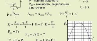
The general dependence of electrical power on electric current and voltage has been known for a long time: this is the product. Let's multiply the current by the voltage - we get the value of this value consumed by the circuit from the network.
But in reality everything may not be so simple. Because by simply multiplying the voltage by the current, we get the total power value. It would seem that this is what you need! After all, we are usually interested in the full value of any quantity.
However, this relationship cannot be extended to electrical power, since the electricity and power on the basis of which the readings of our apartment meter change are not total, but active.
Active power
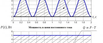
- this is the power that is consumed at the moment when there is both voltage and electric current synchronous with it at the same moment in the network. In fact, in DC circuits, with the exception of transient processes during on-off switching, this is what happens.
The voltage constantly “presses”; if the circuit is closed, a certain current constantly “presses”. As a result, the apparent and active power become equal, since current and voltage act in concert.
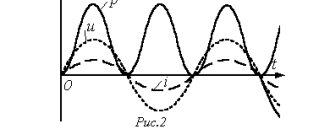
AC circuits are a different matter. The voltage in them changes its direction fifty times per second, and the current... sometimes lags behind, and sometimes leads the voltage. For example, if there is “inductance” in a circuit, that is, a coil of wire with many turns, then the current on such a circuit element will “lag” behind the voltage.
The reason is the back EMF of self-induction resisting the change in current in the coil. It turns out that the voltage has already been applied to the inductance, and the current cannot yet increase due to interference from the back-EMF.
Among students at many electrical engineering universities, there is the following artistic comparison: “It takes time for the current to run through each turn, but the voltage is there, already at the ends of the coil.”
The counter-induction emf causes a voltage drop and a decrease in current in the circuit. That is, the coil is a source of inductive reactance. But it differs from active resistance in that it does not generate any heat and does not consume any power at all in the usual sense.
There is simply an “empty” transfer of electricity from the source to the inductance. And the energy, redirected back and forth like a ball in table tennis, does not leave the network anywhere. This is reactive energy and the consumer at home does not have to pay the energy sales company for it.
Reactive Energy
, produced in the network per unit time, can be considered reactive power. It is calculated in the same way as the active one - by multiplying the reactive component of the current and the voltage.
The reactive component of the current is the one that does not coincide with the voltage in phase. The amount of “mismatch” is characterized by the phase shift angle. In the case of pure inductance, the phase shift is a maximum of 90°. This means that when the voltage reaches its highest value, the current is just beginning to rise.
And if there is a capacitor (capacitance) in the circuit, then the voltage, on the contrary, will lag behind the current by 90 degrees due to the fact that for a voltage drop to occur, the capacitor needs to charge its plates.
In the same way, the source and capacitor in the same circuit will exchange reactive energy, which will not be wasted on anything.
In a real circuit there is no purely active or purely reactive load, so the total power always consists of an active and reactive component, and the phase angle is between zero and 90°.
The reactive component of the current is equal to its product times the sine of the phase angle, and the active component is equal to the product times the cosine of this angle:
Q=I*sinφ; P=I*cosφ
The total power can be found using the Pythagorean theorem:
S=√(P^2+Q^2);
At the same time, reactive power, unlike active power, cannot be calculated in watts, because it is inefficient. Therefore, a special unit of measurement was invented for reactive power - reactive volt-amperes (VARs). And the total is measured in volt-amperes, without specifying the nature of the load.
Calculations
To calculate the total power, use the formula in complex form. For example, for a generator the calculation looks like:
And for the consumer:
But let’s put this knowledge into practice and figure out how to calculate power consumption. As you know, we, ordinary consumers, pay only for the consumption of the active component of electricity:
P=S*cosФ
Here we see a new value of cosФ. This is the power factor, where Ф is the angle between the active and full components of the triangle. Then:
cosФ=P/S
In turn, reactive power is calculated using the formula:
Q = U*I*sinФ
To reinforce the information, watch the video lecture:
All of the above is also true for a three-phase circuit; only the formulas will differ.