The author of the article is a professional tutor, author of textbooks for preparing for the Unified State Exam Igor Vyacheslavovich Yakovlev
Topics of the Unified State Examination codifier: alternating current, forced electromagnetic oscillations.
Alternating current carries energy. Therefore, the issue of power in the AC circuit is extremely important.
Let and be the instantaneous values of voltage and current in a given section of the circuit. Let's take a short time interval - so small that the voltage and current will not have time to change any during this time; in other words, the values and can be considered constant during the interval.
Let a charge pass through our section over time (in accordance with the rule for choosing the sign for the current strength, a charge is considered positive if it is transferred in a positive direction, and negative otherwise). The electric field of moving charges performed work
Current power is the ratio of the work done by the electric field to the time during which this work is done:
(1)
We received exactly the same formula at one time for direct current. But in this case, power depends on time, oscillating together with current and voltage; therefore quantity (1) is also called instantaneous power
.
Due to the presence of a phase shift, the current strength and voltage in the area do not have to coincide in sign (for example, it may happen that the voltage is positive and the current strength is negative, or vice versa). Accordingly, power can be either positive or negative. Let's look at both of these cases in a little more detail.
1. Power is positive
: .
Voltage and current have the same signs. This means that the direction of the current coincides with the direction of the electric field of the charges forming the current. In this case, the energy of the section increases: it enters this section from an external circuit
(for example, the capacitor is charged).
2. Power is negative
: . Voltage and current have different signs. Therefore, the current flows against the field of moving charges that form this very current.
How can this happen? It’s very simple: the electric field that arises in the area, as it were, “outweighs” the field of moving charges and “pushes” the current against this field. In this case, the energy of the section decreases: the section gives off energy to the external circuit
(for example, the capacitor is discharging).
If you don’t quite understand what was just discussed, don’t worry - further on there will be specific examples in which you will see everything.
Current power through resistor
Let alternating current flow through a resistor with a resistance of . The voltage across the resistor, as we know, oscillates in phase with the current:
Therefore, for instantaneous power we obtain:
(2)
The graph of power (2) versus time is shown in Fig. 1. We see that the power is non-negative all the time - the resistor takes energy from the circuit, but does not return it back to the circuit.
Rice. 1. AC power through resistor
The maximum value of our power is related to the amplitudes of current and voltage by the usual formulas:
In practice, however, what is of interest is not the maximum, but the average
current power. This is understandable. Take, for example, an ordinary light bulb that is lit in your home. A current with a frequency of Hz flows through it, i.e., fluctuations in current and voltage occur per second. It is clear that over a sufficiently long time, a certain average power is released from the light bulb, the value of which is somewhere between and . Where exactly?
Look again carefully at Fig. 1. Don’t you have an intuitive feeling that the average power corresponds to the “middle” of our sinusoid and therefore takes on the value ?
This feeling is absolutely true! The way it is. Of course, we can give a mathematically strict definition of the average value of a function (in the form of some integral) and confirm our guess with direct calculation, but we don’t need this. An intuitive understanding of a simple and important fact is enough:
the average value of the square of the sine (or cosine) over the period is equal to
.
This fact is illustrated in Figure 2.
Rice. 2. The average value of the squared sine is
So, for the average value of the current power across the resistor we have:
(3)
In connection with these formulas, the so-called active
(or
effective
) values of voltage and current (in fact, these are nothing more than the
root mean square
values of voltage and current. We have already encountered this: the root mean square speed of the molecules of an ideal gas (sheet “Equation of State of an Ideal Gas”):
(4)
Formulas (3), written in terms of effective values, are completely similar to the corresponding formulas for direct current:
Therefore, if you take a light bulb, connect it first to a constant voltage source, and then to an alternating voltage source with the same effective value, then in both cases the light bulb will burn equally brightly.
The effective values (4) are extremely important for practice. It turns out that AC voltmeters and ammeters show exactly the effective values
(that's how they are designed).
Know also that the notorious volts from the outlet are the effective
value of the household power supply voltage.
How to find out what power is in an AC circuit
It is worth pointing out that this is a value that is directly related to other indicators. For example, it is directly dependent on time, force, speed, vector of force and speed, modulus of force and speed, moment of force and speed of rotation. Often in formulas when calculating electrical power, the number Pi is also used with the resistance indicator, instantaneous current, voltage in a specific section of the electrical network, active, total and reactive power. Direct participants in the calculation are the amplitude, angular velocity and initial current strength with voltage.
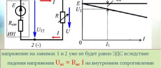
In a single-phase circuit
You can understand what power indicator is in a single-phase alternating current circuit by using a current transformer. To do this, you need to use a wattmeter, which is connected through a current transformer. The readings should be multiplied by the transformer current coefficient. When measuring power at high voltage, a current transformer is needed to insulate the wattmeter and ensure the safety of the user. The parallel circuit is not connected directly, but thanks to a voltage transformer. Secondary windings with housings of measuring transformer installations must be grounded to avoid accidental insulation damage and high voltage contact with devices.
Note! To determine the parameters in the network, it is necessary to multiply the ammeter by the transformer current coefficient, and multiply the numbers obtained by the voltmeter by the transformer voltage coefficient.
In a three-phase circuit
In an alternating current circuit, the power indicator in a three-phase circuit can be determined by multiplying the current by the voltage. Since this is not a constant electric current, it depends on time and other parameters, so it is necessary to use other proven circuits. So, you can use a wattmeter.
The measurement must be carried out in only one phase and multiplied by three according to the formula. This method saves equipment and reduces measurement dimensions. Used for high precision measurement of each phase. In case of an asymmetrical load, you need to use the appropriate wattmeter connection diagram. This is a more accurate method, but requires three wattmeters.
Note! If the circuit does not provide for the presence of a neutral conductor, an appropriate circuit is also needed.
It is worth pointing out that today it is possible to measure the necessary indicators not only with an analogue, but also with a digital device. The difference between the second one is its reduced size and lightness. In addition, digital units have ways to record current with voltage, network cosine, and others. This makes it possible to monitor various quantities from a distance and transmit warnings if there is a deviation. This is convenient because you don’t need to measure current with voltage, and then, using formulas, calculate everything thoroughly.
In general, power is a quantity whose main purpose is to show the strength of a particular device and, in many cases, the speed of activity interacting with it. It can be mechanical, electrical, hydraulic and for direct current and alternating current. Measured according to the international system in watts and kilowatts.
Energy savings and precise system control are the main reasons for using frequency converters in HVAC (Heating, Ventilation and Air Conditioning) systems . Energy conservation is important because a small reduction in the speed of a fan or centrifugal pump has a very large impact on its energy consumption.
The efficiency of fans or pumps together with the frequency converter remains high at lower speeds. Engine efficiency, however, decreases as the engine becomes underutilized. Variable speed drive manufacturers have attempted to improve the low speed efficiency of motors using a number of design solutions. Unfortunately, most of these solutions require laborious manual adjustments and still fail to optimize engine efficiency under all conditions.
The VLT HVAC Drive has a unique control function called Automatic Energy Optimization (AEO). With this function, the frequency converter automatically increases the motor efficiency to the maximum in all operating conditions.
The reason for reduced motor efficiency at light loads and how AEO counteracts this natural tendency is discussed below. The uses and limitations of this feature are also discussed.
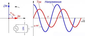
Current power through the capacitor
Let an alternating voltage be applied to the capacitor. As we know, the current through a capacitor is ahead of the voltage in phase by:
For instantaneous power we get:
A graph of instantaneous power versus time is shown in Fig. 3.
Rice. 3. AC power through capacitor
What is the average power value? It corresponds to the “middle” of the sinusoid and in this case is equal to zero! We see this now as a mathematical fact. But it would be interesting to understand from a physical point of view why the current power through the capacitor turns out to be zero.
To do this, let's draw graphs of voltage and current in the capacitor over one oscillation period (Fig. 4).
Rice. 4. Voltage across the capacitor and current through it
Let's consider all four quarters of the period sequentially.
1. First quarter
, . The tension is positive and increasing. The current is positive (flows in the positive direction), the capacitor is charged. As the charge on the capacitor increases, the current decreases.
Instantaneous power is positive: the capacitor stores energy coming from the external circuit. This energy arises due to the work of an external electric field that pushes charges onto the capacitor.
2. Second quarter
, . The tension remains positive, but is subsiding. The current changes direction and becomes negative: the capacitor is discharged against the direction of the external electric field. At the end of the second quarter, the capacitor is completely discharged.
Instantaneous power is negative: the capacitor releases energy. This energy returns to the circuit: it is used to do work against the electric field of the external circuit (the capacitor, as it were, “pushes” the charges in the direction opposite to the one in which the external field “wants” to move them).
3. Third quarter
, . The external electric field changes direction: the voltage is negative and increases in magnitude. The current is negative: the capacitor is charging in the negative direction.
The situation is completely similar to the first quarter, only the signs of voltage and current are opposite. The power is positive: the capacitor again stores energy.
4. Fourth quarter
, . The voltage is negative and decreases in magnitude. The capacitor is discharged against the external field: the current strength is positive.
Power is negative: the capacitor returns energy to the circuit. The situation is similar to the second quarter - again with the replacement by replacing the signs of current and voltage with opposite ones.
We see that the energy taken by the capacitor from the external circuit during the first quarter of the oscillation period is completely returned to the circuit during the second quarter. This process is then repeated again and again. This is why the average power consumed by a capacitor turns out to be zero.
Characteristics
Alternating current flows through a circuit and changes its direction with magnitude. Creates a magnetic field. Therefore, it is often called periodic sinusoidal alternating electric current. According to the law of a curved line, its value changes after a specific period of time. That's why it's called sinusoidal. Has its own parameters. The important ones are to indicate the period with frequency, amplitude and instantaneous value.
A period is the time during which the electric current changes, and then it repeats again. Frequency is the period per second. Measured in hertz, kilohertz and millihertz.
Amplitude is the maximum current value with voltage and flow efficiency over a full period. Instantaneous value is an alternating current or voltage that occurs during a specific time.
Current power through the coil
Let alternating voltage be applied to the coil. The current through the coil lags in phase from the voltage by:
For instantaneous power we get:
Again the average power is zero. The reasons for this are, in general, the same as in the case of a capacitor. Let's look at the graphs of voltage and current through the coil over a period (Fig. 5).
Rice. 5. Voltage on the coil and current through it
We see that during the second and fourth quarters of the period, energy enters the coil from the external circuit. In fact, voltage and current have the same signs, the current increases in magnitude; To create a current, the external electric field does work against the vortex electric field, and this work goes to increase the energy of the magnetic field of the coil.
In the first and third quarters of the period, the voltage and current have different signs: the coil returns energy to the circuit. The vortex electric field, which maintains a decreasing current, moves charges against the external electric field and thereby does positive work. How is this work accomplished? Due to the energy previously accumulated in the coil.
Thus, the energy stored in the coil during one quarter of the period is completely returned to the circuit during the next quarter. Therefore, the average power consumed by the coil is zero.
The influence of current frequency on electrical appliances
Next, we consider the influence of the frequency of electric current. An increase in frequency to relatively low values (1 - 10 thousand Hz) is usually a consequence solely of an increase in the rated power of electrical equipment, since this increases the conductivity of the gas gaps. Frequency meters are used to measure frequency in the system.
A steam turbine is designed and built in such a way that at rated rotation speed (frequency) it provides maximum shaft power output. In this case, a decrease in the nominal frequency is a consequence of the occurrence of losses due to the impact of steam on the blades with a simultaneous increase in the torque, and an increase in frequency leads to a decrease in the torque.
Thus, the most economical operating mode is achieved at the optimal frequency.
In addition, operation at lower frequencies leads to accelerated wear of the rotor blades and other parts and mechanisms. A decrease in frequency affects the station's own consumption.
Power is what characterizes the speed of transmission with the conversion of electricity. What are the power standards in the AC network and types, what are active and reactive power? More on this and more below.
Links[edit]
- "Importance of Reactive Power to the System". March 21, 2011. Archived May 12, 2015. Retrieved April 29, 2015.
- Definition of active power in the International Electrotechnical Dictionary Archived April 23, 2015, at the Wayback Machine
- IEEE 100: The Authoritative Dictionary of IEEE Standards Terms.-7th ed.
ISBN 0-7381-2601-2, page 23 - "August 14, 2003 Shutdown - Sequence of Events" (PDF). FERC. 2003-09-12. Archived from the original (PDF) on October 20, 2007. Retrieved February 18, 2008.
- Close, Charles M. Analysis of Linear Circuits
. P. 398 (section 8.3). - "Archival copy". Archived from the original on 2015-10-25. Retrieved April 29, 2015.CS1 maint: archived copy as title (link)
- ^ a b
Emanuel, Alexander (July 1993).
“On determining the power factor and total power in asymmetrical polyphase circuits with sinusoidal voltages and currents.” IEEE Transactions on Power Delivery
.
8
(3):841–852. DOI: 10.1109/61.252612.
Reactive power control [edit]
Transmission-connected generators are usually required to maintain the flow of reactive power. For example, in the UK transmission system, generators are required by the grid code to provide power ratings ranging from a lagging power factor of 0.85 to a leading power factor of 0.90 at designated terminals. The system operator will perform switching actions to maintain a safe and economical voltage profile while maintaining the reactive power balance equation:
G enerator MVAR s + S ystemgain + S huntcapacitors = MVARD emand + R eactivelosses + S huntreactors {\displaystyle \mathrm {Generator\ MVARs+System\ gain+Shunt\ capacitors=MVAR\ Demand+Reactive\ losses+Shunt\ reactors} }
"System gain" is an important source of reactive power in the above power balance equation, which is created by the capacitive nature of the transmission network itself. By taking decisive switching action early in the morning, before demand increases, system gains can be maximized early, helping to protect the system throughout the day. To balance the equation, it would be necessary to run the reluctance generator to capacity. Other sources of reactive power that will also be used include shunt capacitors, shunt reactors, static VAR compensators and voltage control circuits.