What is the difference between resistance and conductivity?
Resistance, by definition, is a measure of the "friction" a component presents for current to flow through it. Resistance is symbolized by the capital letter "R" and is measured in units of "ohms". However, we can also think of this electrical property in its inverse: how easy it is for current to flow through a component, rather than how difficult it is.
If resistance is the term we use to express a measure of how difficult it is for current to flow, then a good term to express how easily current flows would be conductance. Mathematically, conductivity is the reciprocal of resistance:
\[conductivity = \frac{1}{resistance}\]
The greater the resistance, the less the conductivity; and vice versa.
This should be intuitive because resistance and conductance are opposite ways of referring to the same important electrical property.
If we compare the resistances of two components and find that component "A" has half the resistance of component "B", then alternatively we could express this relationship by saying that component "A" is twice as conductive as component " B". If component "A" has a resistance equal to only one-third that of component "B", then we can say that it is three times more conductive than component "B", and so on.
Currents in the circuit
The nature of the change in these dependencies is obvious and can be justified using the dependencies discussed in paragraphs 1-3. The graphs are shown in Fig. 14.
- Powers
S
,
P
,
Q in the circuit.
Active power throughout the circuit
;
reactive power varies linearly with C
dependence of total power on C
is similar to addiction because
Graphs of these dependencies are shown in Fig. 15.
The section of the circuit in which current resonance occurs is called a parallel resonant circuit. When currents resonate, in accordance with (12), it becomes the minimum possible value. As follows from (5), by reducing the active resistance of the inductor and increasing it, you can significantly reduce the conductivity. Those. significantly increase the circuit resistance during current resonance. If this circuit is powered from a source of a sinusoidal signal, the current of which weakly depends on the resistance of the circuit (the so-called current source model), then with current resonance, the voltage on the branches can be several tens or hundreds of times higher than this voltage in other operating modes. This allows you to use such circuits for high-quality isolation of a signal of a certain (resonant) frequency while searching for the desired radio station when receiving its signal. Therefore, current resonance is widely used in radio engineering, television, wired telecommunications technology, measuring technology, and in special secondary power supplies for industrial electronics devices.
Conductivity unit
As a continuation of this idea, the symbol and unit for measuring conductivity were invented. The symbol was a capital letter "G" and the unit of measurement was mho, which means "ohm" spelled backwards (you thought electronics people didn't have a sense of humor?).
Despite their relevance, the mho units were replaced in subsequent years by the Siemens unit (abbreviated "Sm", or, in English literature, "S"). This decision to change the names of units of measurement is reminiscent of changing the temperature unit from degrees centigrade to degrees Celsius, or changing the unit measure frequency cps (cycles per second) in hertz. If you are looking for some kind of renaming pattern here, then Siemens, Celsius and Hertz are the names of famous scientists whose names, unfortunately, tell us less about the nature of the units than their original designations.
Returning to our parallel circuit example, we should be able to see that multiple paths (branches) for current reduce the overall resistance of the entire circuit, since current can flow more easily through an entire circuit of several branches than through any one of them individually. In terms of resistance, additional branches result in a smaller overall value (current encounters less resistance). However, from a conductance perspective, additional branches result in a larger overall value (current flows with greater conductivity).
Circuit with an ideal capacitive element
Educational material: lecture
At any section of the alternating current circuit, irreversible processes of converting electrical energy into other types are simultaneously carried out and the action of an alternating electromagnetic field is manifested.
When solving most electrical problems, assumptions are introduced that allow each of the phenomena to be taken into account separately and simplify the task of calculating AC electrical circuits.
Circuit with an ideal resistive element.
Let us consider, for example, the processes occurring in an ordinary incandescent lamp connected to an alternating current network. There is electrical capacitance between the individual turns of the filament, and the filament has a certain inductance, but these are insignificant. Therefore, it is considered that C=0 and L=0. In this case, when analyzing an electrical circuit, the lamp is called an ideal resistive circuit element with resistance R.
The value of resistance to alternating current is greater than resistance to direct current, due to the uneven distribution of current in the wire (surface effect). Therefore, in contrast to direct current resistance, resistance in an alternating current circuit is called active resistance
.
Active resistance is measured in ohms
.
If voltage u = Um sinωt) is connected to resistance R, then current flows through it
This shows that the voltage across the resistance and the current flowing through it are in phase: .
The voltage that is in phase with the current is called active voltage and is designated Ua.
Circuit with an ideal inductive element.
An example of an ideal inductive element is an inductive coil. The electrical energy released in the coil due to heating of the winding wire is, as a rule, small, as is the interturn capacitance, and in many practical cases they can be neglected (R=0, C=0). Under the accepted assumptions, the inductive coil is called an ideal inductive circuit element or L-element.
The parameter of an ideal inductive element is the inductance L
, and the energy processes in it are determined only by phenomena occurring in the magnetic field.
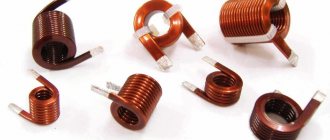
Inductance is the coefficient of proportionality between the electric current flowing in any closed circuit and the magnetic flux created by this current through the surface of which this circuit is the edge. On electrical circuits, conventional graphic symbols of inductors are used, examples of which are shown in the figure.
Conventional graphic symbols of inductances:
a – designation of the inductor; b – with a magnetodielectric core;
c – with ferromagnetic core
When an electric current passes through a coil, the current will create an alternating magnetic flux F. The power lines of this flux, crossing the turns of the coil, will induce an emf in it. self-induction. According to the law of electromagnetic induction
eL=
Since there is no active resistance in the circuit where the inductance L is connected (an ideal inductor is considered), then according to Kirchhoff’s second law u+eL=0, i.e. u = -eL Consequently, the source voltage is always equal in magnitude and opposite facing the direction e. d.s. self-induction.
If we substitute the current value into the formula and differentiate, we get:
Let us denote the value of ωL· equal to the voltage amplitude Um. Then according to Ohm's law
The quantity is called inductive reactance
, measured in Ohms and designated
Since , the initial phase of the voltage can be represented as φ u= φ i+ 90 and, therefore,
The derived relationship shows that if a sinusoidal current flows in the coil, then the voltage also has a sinusoidal character, but at the same time it is ahead of the current by a quarter of a period (90°).
Circuit with an ideal capacitive element
A capacitor is an element of an electrical circuit designed to use its capacity. The capacitor stores the energy of the electric field. The property of an element to store electric charge is characterized by capacity (C)
.
This parameter is the proportionality coefficient between the charge q (C)
and the applied voltage
u (V).
q = C u,
When the voltage on the capacitor changes, the charge changes and an electric current occurs.
An idealized capacitor has only capacitance C (R=0, L=0).
Let's consider electrical processes in a circuit with an ideal capacitive element. Let the source voltage vary according to the law u = Um·sinωt, (φu = 0).
Current occurs in the circuit
From the resulting expression it is clear that the initial phase of the current is φi = . The phase angle between voltage and current is
Consequently, the voltage sinusoid across the capacitance lags behind the current sinusoid by an angle of 90°. In practice, if the voltage in an electrical circuit is out of phase with the current, the load is said to be capacitive.
The current amplitude will be equal to Im = ω·C·Um= .
The quantity is called capacitance
capacitor and measured in Ohms
Xc=1/ ω•C =1/2πfC.
So, in AC circuits the following types of resistance are distinguished:
- active
(active is the resistance of a resistor). The unit of resistance is Ohm. The resistance of the resistor does not depend on the network frequency.
- reactive (
inductive XL and capacitive XC). The unit of measurement for inductive and capacitive reactance is also Ohm. The amount of inductive reactance depends linearly on frequency. And the value of capacitance is inversely proportional to the network frequency. In circuits with a mixed load connection (active, inductive, capacitive), the reactance of the circuit is called the value
X = XL - XC.
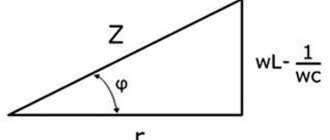
In order to find the total resistance of an electrical circuit with a mixed load connection, the concept of circuit impedance is used, which is defined as
Homework:
1. Answer the questions:
· Explain the physical meaning of the active resistance of a conductor to alternating current compared to the resistance of a conductor to direct current?
· — What is the inductance of the coil? What does it depend on?
· — What is meant by the effective value of alternating sinusoidal current? How to calculate it using the amplitude value of the current?
· — Describe the physical phenomena observed in a resistor in a sinusoidal alternating current circuit?
· — Write down the mathematical relationship between instantaneous voltage, instantaneous current and active resistance?
· — Write down the mathematical expressions for the instantaneous voltage and current on the active resistance, taking the initial phase of the voltage φ=45°.
· — What is meant by phase shift angle? What is it equal to in the section of the circuit with the resistor? inductance? capacity?
· — How to calculate the inductive reactance of an ideal coil?
· — Write down the mathematical expression for the instantaneous voltage on the inductive reactance, taking the initial phase of the current φ=45°.
· — Explain the physical meaning of capacitance. How to calculate the capacitance of an ideal capacitor?
· — What is the phase shift angle in the container?
· — What is meant by the term reactance? How to define it?
· — How is impedance determined in an AC network?
2. Scanned copy or photo of homework, send questions in private messages to the teacher
Textbook
A.S. Kasatkin, M.V. Nemtsov. – 8th ed., revised - M. : Publishing House, 2003.-544 p.
Total parallel circuit conductance
The total conductance of a parallel circuit is greater than that of any of the individual branches because parallel resistors "conduct" better together than individually:
Figure 2 – Parallel circuit admittance
To be more precise, the total conductance in a parallel circuit is equal to the sum of the individual conductances:
\[G_{general} = G_1 + G_2 + G_3 + G_4\]
If we know that conductivity is nothing more than the mathematical reciprocal (1/x) of resistance, we can convert each term in the above formula into resistance by substituting the reciprocal of each corresponding conductivity:
\[\frac{1}{R_{total}} = \frac{1}{R_{1}} + \frac{1}{R_{2}} + \frac{1}{R_{3}} + \frac{1}{R_{4}}\]
Solving the above equation for impedance (instead of the reciprocal of total resistance), we get the following formula:
\[R_{total} = \frac{1}{\frac{1}{R_{1}} + \frac{1}{R_{2}} + \frac{1}{R_{3}} + \ frac{1}{R_{4}}}\]
So, we have finally arrived at our mysterious resistance formula! Conductivity (G) is rarely used as a practical parameter, so the above formula is often used when analyzing parallel circuits.
Basic quantities and methods for calculating an electrical circuit of alternating sinusoidal current
Definition 1
Alternating electric current is an electric current that changes in direction and magnitude over time (in some cases, only its magnitude changes).
In everyday life, alternating sinusoidal current is used for power supply.
Definition 2
Sinusoidal electric current is an electric current that changes over time according to a sinusoidal law.
Graphically, the sinusoidal law is shown in the figure below.
Figure 1. Graph. Author24 - online exchange of student work
Are you an expert in this subject area? We invite you to become the author of the Directory Working Conditions
$I = Imsin * ((2pt / T) + φ) = Imsin * (wt + φ)$
where: Im – maximum value of the amplitude of the electric current; T – time during which one complete oscillation (period) occurs; f – number of oscillations per second (frequency); w – angular frequency; n = 3.14; — f — initial phase
The oscillation frequency is calculated using the following formula:
$f = 1 / T$
The angular frequency is calculated as follows:
$w = 2p * f = 2p / T$
Any sinusoidal function is determined by the following quantities, which are the main characteristics of alternating sinusoidal current:
- Angular frequency.
- Initial phase.
- Amplitude.
To calculate electrical circuits of alternating sinusoidal current, the following methods can be used:
- Operations with sinusoids.
- Conductivity method.
- Symbolic method.
- Method of nodal potentials.
- Loop current method.
- Equivalent generator method.
- Vector diagram method.