History of the appearance of the converter
In the late 1800s, American pioneer electrician Thomas Edison (1847−1931) left his laboratory to demonstrate that direct current (DC) was a better way of delivering electricity than alternating current (AC), which was the new system supported his Serbian rival Nikola Tesla (1856−1943). Edison tried all sorts of clever ways to convince people that AC was too dangerous, from electrocleaning an elephant to advocating the use of AC in the electric chair to control capital punishment. Regardless, Tesla's system won the day, and the world has been running pretty much on the grid ever since.
The only problem is that while many of our appliances are designed to operate with alternating current, low-power generators often produce direct current. This means that if you want to run something like an AC powered gadget from a DC battery in a mobile home, you will need a device that converts the DC to an AC inverter, as it is called.
Which inverter to choose for 12, 24 or 48 Volts
Rechargeable batteries can be 2, 6 and 12 volt, and they can be switched in series or parallel, or series-parallel, increasing their total capacity. Most often, inverters are produced designed for 12 V or 24 V or 48 V. It is very rare to find 96 V models, because such tension is already considered dangerous. Voltage 12 V can be found in the on-board network of a car, 24 V - in buses and on yachts. In principle, any of these voltages can be used with an inverter to provide uninterrupted power to electrical equipment at home. However, low voltage does not technically allow for greater power. So, for example, it is impossible to obtain a power of more than 3 kW from 12 volts, more than 9 kW from 24 volts, and more than 18 kW from 48 volts. It is clear that high-frequency inverters are usually made at 12 V and with a power of up to 3 kW (and they are designed for use in cars), and powerful low-frequency inverters are usually represented by 24 or 48 V models with a power of 3 kW and above (and they are designed for use in a home or building). This is on average. But there are exceptions when, for example, high-frequency inverters, primarily due to their low price, try to occupy their niche in the home segment, or vice versa, uninterruptible power supplies made using low-frequency technology with a toroid power of only 900 W, having a relatively large weight and price, are trying to occupy a niche in the segment of high-frequency inverters due to its qualities such as reliability, powerful charging capabilities and wide functionality.
Electricity DC and AC
When science teachers explain the basic idea of electricity as the flow of electrons, they usually talk about direct current (DC). We learn that electrons are a bit like a line of ants, walking along with packets of electrical energy in the same way that ants carry leaves. This is a pretty good analogy for something like a basic flashlight, where we have a circuit (a solid electrical loop) connecting a battery, a lamp, and a switch, and electrical energy is systematically transported from the battery to the lamp until all the battery's energy is depleted.
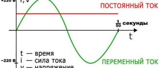
In larger appliances, electricity works differently. The power source, which comes from a wall outlet, is based on alternating current (AC), where the electricity switches between 50 and 60 times per second (in other words, at a frequency of 50 and 60 Hz). It's hard to understand how AC delivers energy when it's constantly changing its mind about where it's going. If the electrons coming out of the wall socket travel, say, a few millimeters down the cable, then they need to reverse the direction and go back, just like how do they ever get to the lamp on the table to make it light up?
The answer is actually quite simple. Imagine that the space between the lamp and the wall is filled with electrons. When you flip the switch , all the electrons filling the cable vibrate back and forth in the lamp filaments - and this rapid shuffling converts electrical energy into heat and lights the lamp. Electrons do not necessarily have to rotate in a circle to transfer energy: in AS they simply “run in place.”
The use of capacitors and freewheeling diodes in circuits of autonomous resonant inverters
A certain increase in conversion efficiency is achieved by introducing various additional elements into the resonant inverter circuit. Most often, capacitors and so-called are used. freewheeling diodes.
Capacitor C1 in Figure 6 is connected in parallel with the load if it has significant inductance. The purpose of this element is to maximize the cosφ parameter.
The essence of the use of the so-called reverse diodes, which are switched in counter-parallel to each key element, is to create conditions for the recovery of energy accumulated in the reactive elements by returning it to a constant voltage source.
Any of the reverse diodes is locked in the open state of the key element and opens upon transition to the locked state, which allows you to “reset” the energy of the reactive elements L and C back to the “I” source.
What is an inverter
One of the legacies of Tesla (and his business partner George Westinghouse, boss of the Westinghouse Electrical Company) is that most of the appliances we have in our homes are specifically designed to run on AC power. Appliances that require DC current but draw power from an AC outlet require an additional piece of equipment called a rectifier, typically made of electronic components called diodes, to convert AC to DC.
An inverter does the opposite job, and it's pretty easy to understand. Let's say you have a battery in a flashlight and the switch is closed, so the DC flows through the circuit always in the same direction as the race car around the track. Now, if you take the battery out and turn it around, assuming it's the other way, it will almost certainly still produce light and you won't notice any difference in the light you get - but the electrical current will flow in the opposite way.
Let's say you had lightning-fast hands and they were dexterous enough to turn the battery over 50-60 times per second. Then you would become a kind of mechanical inverter , turning the battery's DC power into AC power at a frequency of 50-60 Hz.
Of course, that's not how the inverters you buy at electrical stores work, although some are truly mechanical: they use electromagnetic switches that quickly switch to the current direction. Inverters like this often produce what's called a square-wave output: current either flows one way or the other way around, or it switches instantly between the two states.
Such sudden changes in direction are dangerous for some types of electrical equipment. At normal AC power, it gradually changes from one side to the other in the form of a sine wave.
Electronic inverters can be used to create this kind of smoothly varying AC output from a DC input. They use electronic components called inductors and capacitors to increase and decrease the output current than the sharp, square wave on/off output you get with a basic inverter.
Inverters can also be used with transformers to change a certain DC input voltage to a completely different AC output voltage (higher or lower), but the output power must always be less than the input power. The law of conservation of energy implies that an inverter and transformer cannot supply more energy than they consume, and some energy must be lost as heat as electricity flows through various electrical and electronic components. In practice, inverter efficiency often exceeds 90 percent, although basic physics tells us that some energy - whatever it is - is always lost somewhere.
Additional protection
A modern inverter must have short circuit protection. It installs a safety device against accidental exposure to outside interference, especially when it comes to children.
Overload protection must be triggered in a timely manner to prevent overheating of the wiring and subsequent fire. The protection unit protects the converter from short circuits and high input voltage. For this purpose, there are indicators that show the state of the electrical network.
Additional sensors and installed voltmeters will help identify the corresponding malfunction. System temperature indicators located on the cooling radiator will allow you to control the fan when the readings exceed the permissible value.
How the device works
Imagine being a DC battery and someone taps you on the shoulder and asks you to produce an AC battery instead. How would you do it? If all the current you produce flows in one direction, how about adding a simple switch to your output? Turning your current on and off can very quickly provide DC pulses that could do at least half the work. To make a proper AC , you will need a switch that allows you to completely cancel the current and do this about 50-60 times per second. Visualize yourself as a human battery, changing contacts back and forth more than 3,000 times per minute.
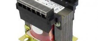
Essentially, an old-fashioned mechanical inverter boils down to a switching box connected to a transformer. And since electromagnetic devices that change low-voltage alternating current to high-voltage current or vice versa, using two coils of wire (called primary and secondary) wound around a common iron core.
In a mechanical inverter , either an electric motor or some other automatic switching mechanism reverses the incoming current back and forth basically simply by changing the contacts and generates an AC in secondary mode. The switching device works in the same way as in an electric doorbell. When power is connected, it magnetizes the switch, pulls it out, and turns it off very quickly. The spring will push the switch back, turning it on, and then repeat the process over and over again.
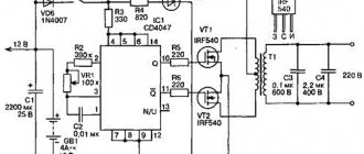
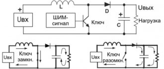
The switching frequency is set by control signals generated by the control circuit (controller). The controller can also solve additional tasks:
- Voltage regulation.
- Synchronization of key switching frequency.
- Protecting them from overloads.
Specifications
All electrical converters output a standard frequency of 50 Hz and a voltage of 220 V. This output meets the requirements of home electricity and is compatible with all consumers. The main parameters include:
- rated power;
- efficiency;
- active or passive cooling system;
- electricity consumption at idle;
- the value of the maximum current consumption at the input;
- supply voltage;
- protection devices against short circuits and overheating of equipment.
Old inverter designs are current transformers, while modern models are assembled on pulse controllers, ensuring high efficiency of the devices. Sometimes this value reaches 95%, and the remaining 5% is dissipated by the device itself, due to which it heats up.
Depending on the model of the 12-220 volt inverter, consumers receive a rectangular sine wave voltage at the output, or in more expensive designs it corresponds to the standard value. Some devices with high starting power cannot be started from a converter.
To do this, it is necessary to use adapters consisting of capacitors that can provide sufficient starting current. Sometimes it is simply necessary to limit the use of certain electrical equipment.
How does an inverter-type welding machine work?
Due to its technical characteristics, the inverter can be used to perform welding with various types of electrodes. This device is distinguished by its compact size and light weight, which makes it very mobile, unlike heavy and large transformers. It is also convenient that such a welder can generate both direct and alternating current.
In order to understand what advantages an inverter has, you need to understand how it works. The operation of this device, which began to gain mass popularity only at the beginning of the 21st century, is based on a completely different principle compared to the operation of a conventional welding transformer.
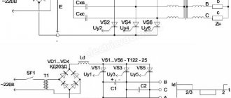
Schematic diagram of the welding inverter "Duga-200" (click to enlarge)
The alternating current supplied to the inverter from a regular electrical network is first rectified by passing through a diode bridge, which is equipped with the electrical circuit of the device. After rectification, the direct current is supplied to power transistors, which convert it back into alternating current, but with an increased frequency. To reduce the voltage of high-frequency alternating current and obtain the welding current of the required strength, a transformer is used in the electrical circuit of the inverter.
Since the voltage reduction of high-frequency current is not carried out according to the same principle as in a conventional welding machine, there is no need to use large transformers for this; a compact device is quite sufficient. After reducing the voltage and increasing the current to the required value, it is supplied to the output rectifier, in which it is converted to constant.
Inverter controls using the example of the Fast and the Furious device (click to enlarge)
The use of high-frequency current generated by the inverter not only makes it possible to significantly reduce the dimensions of the device, but also has a positive effect on the combustion process of the welding arc, which is highly stable. Such a welding machine is characterized by high efficiency, since it does not waste energy on heating the transformer iron.
Simplified diagram of the operation of a welding inverter
Thus, any inverter device consists of such structural elements as:
- a rectifier assembled on the basis of a diode bridge (this electrical circuit block is responsible for rectifying the alternating current coming from the electrical network);
- the inverter itself, which is a generator of high-frequency electrical pulses (the basis of this unit is made up of transistors that open and close at high frequencies);
- a step-down transformer, which solves the problem of lowering the high-frequency voltage and, accordingly, increasing the welding current;
- high-frequency output current rectifier (such a rectifier, like the input unit, is assembled on the basis of a diode bridge);
- a special electronic unit designed to control the operating modes of the inverter apparatus.
